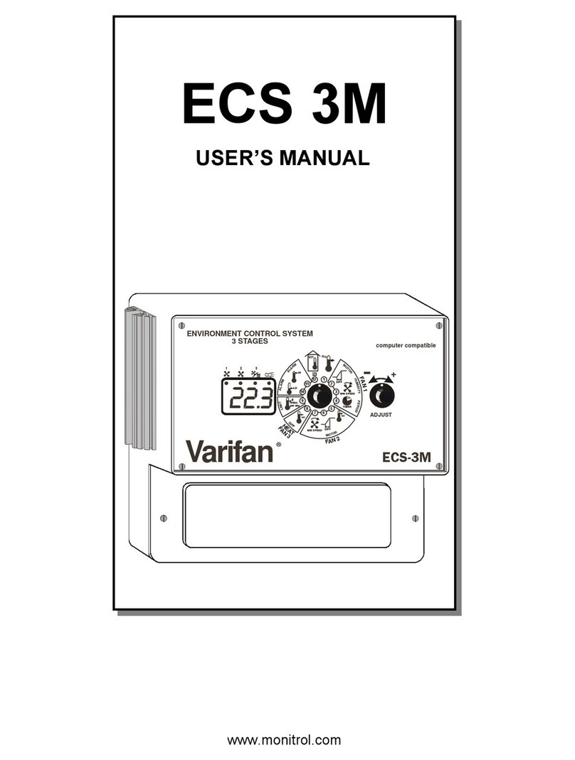
Tecnoalarm TP8-64 BUS User guide

INSTALLER MANUAL
Release: 2.0
Update: September2009
Language English
FWversion: 1.5
TP8-64 BUS
TP8-64 BUS MET
864 ZONES
CONTROL PANEL

II InstallerManual-TP8-64BUS
The features of the control panel can be subject to change without notice.
Unauthorized reproduction or distribution of this manual, or any portion of it, on any device and in any form, is
prohibited.
The contents of this manual may be subject to change without notice.

III
TP8-64BUS-InstallerManual
CONFORMITY
Hereby,Tecnoalarmsrldeclaresthatthepresentequipment is in compliance with the essential requirements and
otherrelevantprovisionsoftheR&TTE1999/05/ECdirective.
Thedeclarationofconformityisavailableonthewebsite:www.tecnoalarm.com.

IV InstallerManual-TP8-64BUS

TP8-64 BUS - Installer Manual Index 1
INDEX
1. GENERAL FEATURES
1.1 HARDWARE 1-1
1.2 MAIN FUNCTIONS 1-2
2. HARDWARE
2.1 CONTROL PANEL 2-1
2.1.1 Composition 2-2
2.2 WALL MOUNTING 2-4
2.3 POWER SUPPLY SECTION 2-6
2.3.1 Mains connection 2-6
2.3.2 Battery connection 2-9
2.4 CPU BOARD 2-10
2.4.1 Power supply section 2-10
2.4.2 Serial ports 2-11
2.4.3 Telephone section 2-11
2.4.4 Terminals 2-12
2.5 INTERNAL INPUT EXPANSION MODULE (OPTION) 2-15
2.5.1 Terminals 2-15
2A. INPUT EXPANSION MODULES
2A.1 INPUT EXPANSION WITH POWER SUPPLY SPEED ALM8 PL 2A-1
2A.1.1 Electronic board and power supply 2A-2
2A.1.2 Transformer 2A-2
2A.1.3 Terminals 2A-3
2A.2 INPUT EXPANSION SPEED 8 2A-4
2A.2.1 Electronic board 2A-4
2A.2.2 Terminals 2A-5
2A.3 INPUT EXPANSION SPEED 4 2A-6
2A.3.1 Electronic board 2A-6
2A.3.2 Terminals 2A-7
2A.4 INPUT EXPANSION SPEED 8 STD 2A-7
2A.4.1 Electronic board 2A-7
2A.4.2 Terminals 2A-8
2A.5 INPUT EXPANSION MODULE WITH POWER SUPPLY SPEED ALM8 PLUS 2A-9
2A.5.1 Electronic board 2A-10
2A.5.2 Transformer 2A-10
2A.5.3 Terminals 2A-11
2A.6 INPUT EXPANSION MODULE SPEED 8 PLUS 2A-12
2A.6.1 Electronic board 2A-12
2A.6.2 Terminals 2A-13
2A.7 INPUT EXPANSION MODULE SPEED 4 PLUS 2A-13
2A.7.1 Electronic board 2A-13
2A.7.2 Terminals 2A-14
2A.8 NOTES FOR ALL INPUT EXPANSIONS 2A-15
2A.9 DIP-SWITCH SETTINGS 2A-15
2A.10 CASING 2A-15
2B. OUTPUT EXPANSION MODULES
2B.1 OUTPUT EXPANSION WITH LOGIC OUTPUTS ESP32-OCN 2B-1
2B.1.1 Electronic board 2B-1
2B.1.2 Casing 2B-1
2B.1.3 Installation 2B-2

Index Installer Manual - TP8-64 BUS
2
2B.2 SUPERVISORY BOARD WITH SIGNALING LED SINOTTICO 32N 2B-2
2B.2.1 Electronic board 2B-2
2B.3 NOTE FOR ALL OUTPUT EXPANSIONS 2B-2
2B.4 DIP-SWITCH SETTINGS 2B-2
2B.4.1 Correspondance addresses-output configuration 2B-3
2C. CONSOLE
2C.1 LCD300/S 2C-1
2C.1.1 Electronic board 2C-2
2C.1.2 Dip-switch settings 2C-2
2C.1.3 Installation 2C-3
2D. KEYPOINTS
2D.1 TP SDN ELECTRONIC KEYPAD 2D-1
2D.1.1 Electronic board 2D-2
2D.2 TP SK6N KEY READER WITH MINI KEYPAD 2D-2
2D.2.1 Function keys 2D-3
2D.2.2 Electronic board 2D-3
2D.3 TP SKN KEY INTERFACE 2D-3
2D.3.1 Electronic board 2D-4
2D.3.2 Tamper protection of the key readers 2D-4
2D.4 NOTES FOR ALL KEYPOINTS 2D-5
2D.5 DIP-SWITCH SETTINGS 2D-5
2E. PROGRAMMING INTERFACES
2E.1 PROGRAMMING INTERFACE PROG32 2E-1
2E.1.1 Connection 2E-1
2E.1.2 RS232 interface section 2E-2
2E.1.3 Flash programming section 2E-2
2E.2 MULTIFUNCTIONAL INTERFACE PROG USB 2E-2
2E.2.1 Connection 2E-2
2E.2.2 Interface section 2E-3
2E.2.3 Flash programming section (TTL output only) 2E-3
2E.3 SERIAL BUS EXTENSION SPEED RS485 2E-4
2E.3.1 Electronic board 2E-4
2E.3.2 Casing 2E-5
2F. TELEPHONE COMMUNICATOR WITH GSM MODULE
2F.1 TECNOCELL-PRO PL 2F-1
2F.1.1 Electronic board 2F-1
2G. WIRELESS EXPANSION MODULES (OPTIONAL)
2G.1 RTX200/433868 WIRELESS RECEIVER-TRANSMITTER 2G-1
2G.1.1 Electronic board 2G-1
2G.1.2 Dip-switch settings 2G-2
2G.1.3 433MHz section 2G-2
2G.1.4 868MHz section 2G-2
2G.1.5 Casing 2G-2
2G.2 RX300/433868 WIRELESS RECEIVER 2G-3
2G.2.1 Electronic board 2G-3
2G.2.2 Dip-switch settings 2G-4
2G.2.3 Casing 2G-4
2G.3 TX240-3 WIRELESS KEY 2G-5
2G.3.1 Functioning keys 2G-5

TP8-64 BUS - Installer Manual Index 3
2G.3.2 Synchronization of the code 2G-5
2G.3.3 Battery 2G-5
2G.4 LCD300 WL WIRELESS CONSOLE 2G-6
2G.4.1 Electronic board 2G-7
2G.4.2 Dip-switch settings 2G-7
2G.5 SAEL 2000 WL WIRELESS SIREN 2G-8
2G.5.1 Battery 2G-8
2G.5.2 Electronic board 2G-9
2G.5.3 Dip-switch settings 2G-9
3. SETUP
3.1 DRAFT OF THE INSTALLATION ON PAPER 3-1
3.2 HARDWARE CONFIGURATION BY PC 3-1
3.2.1 Addition or deletion of modules 3-7
3.3 INSTALLATION 3-10
3.3.1 Connection of the modules via RS485 serial bus 3-10
3.3.2 Connection of the modules on sensor bus and sirens bus 3-11
3.3.3 Programming of the addresses of the modules 3-12
4. PROGRAMMING BY PC
4.1 ZONE CONFIGURATION 4-2
4.1.1 Zone list 4-2
4.1.2 Zone-function association 4-7
4.1.3 Zone-programm association 4-8
4.1.4 Options 4-9
4.1.5 Outputs 4-12
4.1.6 Bus sirens 4-13
4.2 CONFIGURATION OF THE TELEPHONE SECTION 4-15
4.2.1 Telephone interface 4-15
4.2.2 Telephone communicator with GSM module 4-18
4.2.3 Report codes 4-19
4.2.4 Opening message 4-20
4.2.5 Remote control 4-22
4.3 CONFIGURATION OF THE TIME PARAMETERS 4-23
4.3.1 Time parameters 4-23
4.3.2 Timer settings 4-25
4.3.3 Access periods 4-27
4.3.4 Customization of the calendar 4-29
4.4 PROGRAMMING OF THE CODES, KEYS AND WIRELESS KEYS 4-31
4.4.1 Programming of the codes 4-31
4.4.2 Programming of the keys 4-33
4.4.3 Programming of the wireless keys 4-34
4.5 CONFIGURATION OF THE WIRELESS SIRENS AND CONSOLES 4-36
4.5.1 Wireless siren configuration 4-36
4.5.2 Wireless console configuration 4-37
4.6 SYSTEM CONFIGURATION SAVING 4-38
4.7 UPLOAD/DOWNLOAD OF SYSTEM CONFIGURATION 4-39
4.7.1 Connection of the PC to the control panel 4-39
4.7.2 Upload (send) configuration 4-39
4.7.3 Indicators of system configuration coherence 4-42
4.7.4 Download (receive) configuration 4-43
5. PROGRAMMING BY CONSOLE
5.1 PRELIMINARY REMARKS 5-1
5.2 PROGRAMMING SEQUENCE 5-3
5.3 ZONE CONFIGURATION 5-4

Index Installer Manual - TP8-64 BUS
4
5.3.1 Programming of the voice message 5-4
5.3.2 Input-zone association (creation of the zone list) 5-4
5.3.3 Definition of the zone type 5-5
5.3.4 Definition of the contact type (for wired zones only) 5-6
5.3.5 Definition of the zone filter 5-6
5.3.6 Definition of the alarm cycles 5-7
5.3.7 Learning of wireless devices 5-7
5.4 CONFIGURATION OF THE WIRELESS SECTION 5-8
5.4.1 Configuration of the wireless sirens 5-8
5.4.2 Configuration of the wireless consoles 5-8
5.4.3 Programming of the serial number of the control panel 5-9
5.5 CLOCK SETTING 5-9
5.6 CONFIGURATION OF THE PROGRAMS 5-10
5.6.1 Zone association 5-10
5.6.2 Programming of the voice message 5-10
5.7 PROGRAMMING OF THE FUNCTIONS 5-11
5.7.1 Zone association 5-11
5.8 PROGRAMMING OF THE TIME PARAMETERS 5-12
5.9 PROGRAMMING OF THE OUTPUTS 5-13
5.9.1 Association of the siren 5-13
5.9.2 Association of the logic output PGM 5-13
5.9.3 Configuration of the buzzer 5-13
5.9.4 Configuration of the programmable outputs 5-14
5.9.5 Programming of the bus sirens 5-15
5.10 PROGRAMMING OF THE TIMERS 5-16
5.10.1 Test call 5-16
5.10.2 Configuration of the timers 5-17
5.10.3 Programming of the access periods 5-18
5.11 PROGRAMMING OF THE REMOTE CONTROLS 5-18
5.11.1 Programming of the voice message 5-18
5.11.2 Programming of activation time 5-19
5.12 CONFIGURATION OF THE CONSOLES 5-19
5.13 CONFIGURATION OF THE WIRELESS KEYS 5-20
5.13.1 Learning of the wireless key 5-21
5.14 PROGRAMMING OF THE TELEPHONE PARAMETERS 5-21
5.14.1 Settings 5-21
5.14.2 PABX number 5-23
5.14.3 Configuration of the channels 5-23
5.14.4 Programming of the callback numbers 5-24
5.14.5 Configuration of the GSM module 5-25
5.14.6 General notes on SMS 5-27
5.15 ASSOCIATION OF THE EVENTS TO THE CHANNELS 5-28
5.15.1 Zone related events 5-28
5.15.2 Program related events 5-28
5.15.3 All the other events 5-29
5.16 PROGRAMMING OF THE OPTIONS 5-29
5.17 PROGRAMMING OF THE CODES 5-31
5.17.1 Programming of the code length 5-31
5.17.2 Programming of the installer code 5-31
5.17.3 Programming of the master code 5-31
5.17.4 Programming of the standard user codes 5-32
5.18 PROGRAMMING OF THE KEYS 5-33
5.18.1 Learning of the keys 5-33
OTHER SETTINGS - WHEN REQUIRED
5.19 ACTIVATION/DEACTIVATION OF THE REMOTE CONTROLS 5-34
5.20 EXCLUSION OF MODULES/ZONES 5-34
5.21 TEST 5-35

TP8-64 BUS - Installer Manual Index 5
5.21.1 Wireless section test 5-35
5.21.2 Zone test 5-36
5.21.3 Indoor siren and battery test 5-36
5.21.4 Outdoor siren and battery test 5-36
5.21.5 Viewing of the firmware version 5-37
5.21.6 Viewing of the vocabulary version 5-37
5.21.7 Viewing of the LED status 5-37
5.21.8 GSM module test 5-37
6. CONTROL BY CONSOLE
6.1 ARMING 6-5
6.1.1 Arming with master code 6-6
6.1.2 Arming with standard user code 6-7
6.1.3 Quick arming (if enabled) 6-7
6.1.4 Arming through key zone 6-8
6.1.5 Automatic arming 6-8
6.1.6 Arming during the access periods 6-8
6.1.7 Arming denied 6-9
6.2 DISARMING 6-9
6.2.1 Disarming with master code 6-9
6.2.2 Disarming with standard user code 6-9
6.2.3 Disarming under duress (if enabled) 6-10
6.2.4 Quick disarming (if enabled) 6-10
6.2.5 Disarming through key zone 6-10
6.2.6 Automatic disarming 6-10
6.2.7 Disarming during the access periods 6-10
6.3 BY-PASS 6-10
6.3.1 Activation of by-pass with code 6-10
6.3.2 Automatic activation of by-pass 6-11
6.3.3 Activation of by-pass during the access periods 6-11
6.3.4 Deactivation of by-pass with code 6-11
6.3.5 Automatic deactivation of by-pass 6-11
6.3.6 Deactivation of by-pass on expiry of maximum by-pass time 6-11
6.4 ACTIVATION/DEACTIVATION REMOTE COTNROLS 6-12
6.5 MANUAL COMMUNICATOR BLOCK 6-12
6.6 VIEWING OF THE EVENT BUFFER 6-13
6.7 RESET OF LED SIGNALING 6-14
6.7.1 Reset of LED signaling with master code 6-14
6.7.2 Reset of LED signaling with installer code (tamper LED signaling) 6-14
QUICK COMMANDS - OPERATIONS WITHOUT CODE
6.8 RELEASE OF PANIC ALARM 6-15
6.9 VIEWING OF ZONE STATUS 6-15
6.10 VIEWING OF ALARM MEMORY 6-15
7. CONTROL BY KEYPOINT
7.1 CONTROL BY TP SK6N KEY READER WITH MINI KEYPAD 7-1
7.1.1 Arming 7-1
7.1.2 Disarming 7-3
7.1.3 By-pass 7-3
7.1.4 Release of panic alarm 7-4
7.2 CONTROL THROUGH TP SKN INTERFACE FOR ELECTRONIC KEYS AND
ATPK KEY READERS 7-4
7.2.1 Arming 7-4
7.2.2 Disarming 7-6
7.2.3 By-pass 7-7
7.3 SPECIAL OPERATING CONDITIONS 7-7

Index Installer Manual - TP8-64 BUS
6
7.3.1 False key alarm 7-7
7.3.2 Simultaneous arming by several control units 7-8
7.3.3 Simultaneous arming with code and key 7-8
7.3.4 Automatic disarming for alarm 7-8
7.3.5 Automatic communicator block 7-8
7.3.6 Trouble/general alarm 7-8
7.4 CONTROL BY TP SDN ELECTRONIC KEYPAD 7-9
7.4.1 Arming 7-9
7.4.2 Disarming 7-11
7.4.3 By-pass 7-11
7.4.4 Special operating conditions 7-12
7.5 TX240-3 WIRELESS KEY 7-13
7.5.1 Arming 7-13
7.5.2 Disarming 7-13
7.5.3 By-pass 7-14
7.5.4 Learning 7-14
8. TECHNICAL SPECIFICATIONS
8.1 TP8-64 BUS CONTROL PANEL 8-1
8.2 TP8-64 BUS MET CONTROL PANEL 8-3
8.3 INTERNAL INPUT EXPANSION MODULE 8-4
8.3.1 Expansion module with 4 inputs 8-4
8.4 SERIAL INPUT EXPANSIONS 8-5
8.4.1 Expansion module with 8 inputs and power supply (SPEED ALM8 PL) 8-5
8.4.2 Expansion module with 8 inputs (SPEED 8) 8-6
8.4.3 Expansion module with 4 inputs (SPEED 4) 8-6
8.4.4 Expansion module with 8 inputs (SPEED 8 STD) 8-7
8.4.5 Expansion module with 8 sensor bus inputs and power supply (SPEED ALM8 PLUS) 8-8
8.4.6 Expansion module with 8 sensor bus inputs (SPEED 8 PLUS) 8-9
8.4.7 Expansion module with 4 sensor bus + 4 standard inputs (SPEED 4 PLUS) 8-9
8.5 CONTROL UNITS 8-10
8.5.1 LCD console 8-10
8.6 KEYPOINTS (SECONDARY CONTROL UNITS) 8-11
8.6.1 Electronic keypad 8-11
8.6.2 Key reader with mini keypad 8-11
8.6.3 Key interface 8-11
8.7 SERIAL OUTPUT EXPANSIONS 8-12
8.7.1 Expansion module with 32 logic outputs 8-12
8.7.2 Supervisory board with 32 LED 8-12
8.8 PROGRAMMING INTERFACES AND SERIAL BUS EXTENSIONS 8-13
8.8.1 RS232-RS485 Interface with flash programmer 8-13
8.8.2 Multifunctional interface with flash programmer 8-13
8.8.3 RS485 serial bus extension 8-13
8.9 TELEPHONE COMMUNICATORS WITH GSM MODULE 8-14
8.9.1 Telephone communicator with GSM module 8-14
8.10 WIRELESS SECTION 8-14
8.10.1 Bidirectional wireless receiver-transmitter 8-14
8.10.2 Wireless receiver 8-15
8.10.3 Wireless key 8-15

TP8-64 BUS - Installer Manual Index 7
APPENDIX A - TRANSMISSION PROTOCOLS
APPENDIX B - SPECIAL PROCEDURES
B.1 RESET OF THE DEFAULT CODES B-3
B.2 COMPLETE DELETION OF SYSTEM CONFIGURATION (RESET OF DEFAULT SETTINGS) B-3
B.3 BACKUP/RESTORE OF THE CONFIGURATION OF THE WIRELESS SECTION B-4
B.4 FIRMWARE UPGRADE B-6
B.5 VOCABULARY UPGRADE B-9
B.6 UPLOAD OF THE OPENING MESSAGE B-12
APPENDIX C - CODE MANAGEMENT
C.1 MODIFICATION OF CODE BY USER C-3
C.1.1 Procedure of modification of the codes C-3
C.2 MODIFICATION OF CODE BY MASTER CODE C-3
C.3 INSTALLER CODE C-4

Index Installer Manual - TP8-64 BUS
8

TP8-64BUS-InstallerManual Generalfeatures 1-1
1. GENERAL FEATURES
TP8-64BUSisawiredcontrolpanel with optional radioexpansion.
TP8-64 controls a minimum of 8 and a maximum of 64 zones, distributed among the CPU board, the internal expansion
module with 4 inputs, the input expansion modules connected via serial line or the optional radio module.
Inaddition,thecontrolpanelprovidesaserialbusfortheconnection oftheRSCdevices (serialdevicesconnectedvia
bus).
Using the optional wireless modules, it is possible to connect the wireless devices, bidirectional sirens and LCD
consoles,workingonthe frequencies433MHzet868MHz.
TwoversionsofTP8-64BUScontrolpanelareavailable:
zTP8-64 BUS control panel in ABS casing design by
zTP8-64 BUS MET control panel in a metal casing
1.1 HARDWARE
POWERSUPPLY
z2Aswitching power supply TP8-64 BUS - 3A switching power supplyTP8-64 BUS MET
zSeparatelymountedtransformer
CASING
zABS casing TP8-64 BUS - Size (L x H x D): 300 x 390 x 100mm
Metal casing TP8-64 BUS MET - Size (L x H x D): 455 x 365 x 110mm
zBattery bay (12V - 7Ah)
INPUTS
zMaximum 64 zone inputs:
• OntheCPUboard
1 high speed SERIAL BUS connector for the connection of expansions modules, consoles, keypads,
LED signaling panels, key readers, etc
1 high speed SERIAL BUS connector for the connection of the RSC sirens with specific power supply for
rechargebattery
4 SENSOR BUS connectors for the connection of max. 8 RSC detectors
• Internalexpansionmodules
4wiredinputs withRDVfilterof theoptionalinternalexpansion module(optional)
14wiredinputexpansionmodulesconnectedviaserialbus(optional):
modules with 8 inputs and 1.8A power supply (SPEED ALM8 PL)
modules with 8 inputs (SPEED8)
modules with 4 inputs (SPEED4)
modules with 8 inputs (SPEED8STD)
The modules of the series SPEED PLUS control both RDV detectors and programmable barriers as well as the
RSCperipherals:
modules with 8 SENSOR BUS inputs (SPEED 8PLUS)
modules with 4 SENSOR BUS inputs + 4 standard inputs (SPEED 4 PLUS)
modules with 8 SENSOR BUS inputs and 1.8A power supply (SPEED ALM8PLUS)
• 32 wirelessinputs(optionaltransmitter/receivermodule) tobeselectedamong 2modulesconnectedvia serialbus:
RTX200/433868
RX300/433868
OUTPUTS
zOntheCPUboard
• ProgrammablelogicoutputsOUT1+andOUT2-(onepositive,theothernegative)
• Relayoutputforindoorsirens(self-poweredandnon)
• Relayoutputforoutdoorsirens
zMax. 32 LED signaling panels with 32 LED or expansion modules with 32 logic outputs:
• 32logicopen-collectoroutputs (ESP32-OCN)
• 32LEDoutputs (SINOTTICO32N)
CONTROLUNITS
zMax.15LCDconsolesformonitoringandprogrammingconnectedviaserialbus (LCD300/S)
zMax. 15 secondary control units:
• Keyinterface (TPSKN)
• Electronickeypad (TPSDN)
• Key reader with mini keypad (TPSK6N)
GSMINTERFACE
z1telephonecommunicatorwithGSM data moduleconnectedviaserialbus (TECNOCELL-PROPL)

Generalfeatures InstallerManual-TP8-64BUS
1-2
TELEPHONESECTION
zIncorporatedtelephoneinterface:
• 8telephonechannels
• 2 call back numbers
zTransmissionofvoicemessages
• customizableopeningmessage
• completevoicedescriptionoftheactivealarms
zDigitaltransmissionsusingthe followingformats:
• registered formats: SLOW, DTMF, FSK (CESA, SIA)
• Tecnoalarmformats:FAST(FSK1200Baudcompatible)
WIRELESSMODULES(OPTIONS)/WIRELESSSECTION
zSupervisionandantimaskingcontrol
zControl of max. 32 wireless devices (detectors, transmitters, contacts...)
zControlof4bidirectionalwirelesssirens and4wirelessconsoles(individuallyprogrammableandsupervised)
zOperatingfrequency:RX433MHz,TX868MHz
zWirelessreceiversand/orreceiver-transmittersconnectedviaRS485serialline
zMax. 32 wireless keys
zCompatiblewiththetransmittersofthefamilyTX1xx,TX2xx,TX3xx
PCCONNECTION
zTTLportfortheconnectionofaPCusingtheinterfaces:
• TTL-RS232 (PROG32)
• RS232TTL-USB-RS485 (PROGUSB)
zProgrammingofthesystemandupgradeofboth thefirmwareandthevocabularyofthecontrolpanel
1.2 MAIN FUNCTIONS
zAccess codes:
• 1 master code
• 1 installer code
• Max.62user codes(permittingarming/disarming,by-pass)
zMax. 32 wireless keys
zMax.32userkeys(permittingarming/disarmingandby-pass)
zMax.8programs
z1,000eventsbuffer
z16timers(permittingautomaticarming/disarming,by-pass/endofby-pass,activation/deactivationremotecontrols)
z8 access periods of the codes/keys/wireless key
zIncorporatedvocalinterfacewithpre-recordedvocabularyandansweringmessageprogrammablebytheuser
zCustomizationofthevoicemessages
• Recordingoftheopeningmessage
• Input/programdescriptionbyvocalmessagescomposedofmax.4wordsselectedfrom thoseprerecordedinthe
vocabularyofthecontrolpanel
zUpdateofthecontrolpanelparameters:
• throughconsolewithguidinglist
• throughinterfacePROG32orPROGUSB
• throughTECNOMODEMorMINIMODEM(viatelephoneline)
zList of 64 inputs (association of the physical to the logical inputs) in order to increase the versatility and to
obtain the best distribution of the inputs independently from the physical position of the modules.
zCustomizableperpetualbiennialcalendar(workingdays,holidays,holiday-eves,summer/wintertime)
zProgrammingofinputparameters(excluded,direct,internal,technical,delayed1 (entry time 1), delayed 2 (entry
time2),hold-up,key(arming/disarmingoftheprogramsenabledfor),tamper)
zBackupandrestoreoftheradiodevicedataseparatefromotherprogrammingpermittingthereplacementof
theCPUboardwithoutreprogrammingoftheradiodevices
VOICESYNTHESIS
zGuidedvocalmenuforaccesstothefollowing functions:
• System status signaling
• Programstatus(armed/disarmed)signaling
• Remotecontrol(remoteactivation/deactivation)
• Remotedigitalverification(RDV)ofall/asingledetector/s
• Programmingoftheopeningmessage

TP8-64BUS-InstallerManual Generalfeatures 1-3
TESTMENU
zGraphicRFmonitoringutilityfortheanalysisofradiofrequenciesreceivedbythereceiver-transmittermodule
zViewingofreceptionofradiosignals
zTestprocedureforthebidirectionalconnectionoftheradiosirensandconsoles
zViewingoftheopen inputs
zVerificationofthepresenceandtheversionofthevocabulary
zSoundingtestofthewiredsirens(indoor and outdoor) andthewirelesssirens.
REMOTEPROGRAMMINGANDMONITORING
TP8-64BUScanbeentirelyprogrammedandmonitoredviatelephonelineusingtheTecnoalarmmodemand
programmingandmonitoringsoftware.
ALARMDEVICES
WARNING
Considerthatthealarmdevices (sirens,logicoutputs,telephonetransmitters)havetobeprogrammed.
Ifno alarm devices is programmed, there will be no alarm signalingincase of alarm.

Generalfeatures InstallerManual-TP8-64BUS
1-4

TP8-64BUS-InstallerManual Hardware 2-1
2. HARDWARE
2.1 CONTROL PANEL
TP8-64 BUS
TheTP8-64BUScontrol paneliscomposedof:
zCPUboardincluding:
• 2Apowersupply
• telephonesection
• 8wiredzoneinputs
zPlug-ininputexpansionboardwithadditional
4wiredzoneinputs(option)
zRadiotransmitter-receiver(option)
zTransformermountedonseparatebase
zCombinesantiopeningandantidetachmenttamper
switch
zBattery of max. 7Ah-12V
zABS casing
• size (L x H x D): 300 x 390 x 100mm
ACCESSORIESANDEXPANSIONSMODULES
zMax. 15 consoles with liquid crystal display (LCD) or
electronickeypadsforsystemprogrammingand/or
control
zMax. 15 keypoints:
• Electronic keypads
• Key readers with mini keypads
• Keyreaders
zInputexpansionmodules(max. 14modules)with:
• 8 inputs and 1.8A power supply unit
• 8 inputs
• 4 inputs
zOutputexpansionmodules(max.32modules)with:
• 32 preset logic outputs
• 32LED
zSerialbusextensionmodule(option)
zGSMinterface
zSerialinterface(option)
WIRELESSMODULES-INCOURSEOF
DEVELOPMENT(OPTION)
zWireless consoles (max. 4)
zWireless control units (max. 32)
zWireless sirens (max. 4)
TP8-64 BUS MET
The TP8-64 BUS MET control panel is the same
as TP8-64 BUS but:
zCPUboardincluding:
• 3Apowersupply
zBatteryof max. 17Ah-12V
zMetal casing
• size (L x H x D): 455 x 365 x 110 mm
TP8-64BUS
TP8-64BUSMET

Hardware InstallerManual-TP8-64BUS
2-2
2.1.1 COMPOSITION
TP8-64 BUS
PROTECTION
Thedetectorpowersupplyoutputsareprotectedbya200mA rapid fuse.
COMPOSITION
TheCPUboard isdividedintothefollowingsections:
zPower supply (battery + separate transformer 230V AC - 30V approx. 40VA)
zSerialbus(connectionof serial busRS485+RS232programming interface andaPC)
zConnectorsforplug-incards(vocabulary,inputexpansion)
zTelephonesection
zTerminals

TP8-64BUS-InstallerManual Hardware 2-3
TP8-64 BUS MET
The same as a TP8-64 BUS but:
PROTECTION
Thedetectorpowersupplyoutputsare protected by a 315mArapidfuse
COMPOSITION
Power supply (battery + separate transformer 230V AC - 28V approx. 60VA )

Hardware InstallerManual-TP8-64BUS
2-4
2.2 WALL MOUNTING
TP8-64 BUS
To fix the plastic casing to the wall use 2 plastic dowels (diameter 8mm + apposite screws) and introduce them into the
holes A and B as indicated in the fig. 1
FIG. 1
This manual suits for next models
1
