Micno KE300A Series User manual

Preface
Thank you for purchasing KE300A series inverters.
This manual describes how to use KE300A series inverter properly. Please read it carefully before
installation, operation, maintenance and inspection. Besides, please use the product after understanding
the safety precautions.
Precautions
In order to describe the product’s details, the drawings presented in this instruction are
sometimes shown without covers or protective guards. When using the product, please make
sure to install the cover or protective guard as specified firstly, and operate the products in
accordance with the instructions.
Since the drawings in this manual are represented examples, some are subject to differ from
delivered products.
This manual may be modified when necessary because of improvement of the product,
modification or changes in specifications. Such modifications are denoted by a revised manual
No..
If you want to order the manual due to loss or damage, please contact our company agents in
each region or our company customer service center directly.
If there is still any problem during using the products, please contact our company customer
service center directly.

Contents
Chapter 1 Safety and Precautions ........................................................................................................1
1.1 Safety Precautions...................................................................................................................1
1.2 Precautions..............................................................................................................................3
Chapter 2 Product Information..............................................................................................................6
2.1 Product Inspection ...................................................................................................................6
2.2 Model Description ....................................................................................................................6
2.3 Description of Nameplate.........................................................................................................6
2.4 Selection Guide........................................................................................................................7
2.5 Technical Specifications............................................................................................................9
2.6 External & Installation Dimensions.......................................................................................... 11
2.7 Routine Maintenance of Inverter.............................................................................................27
2.8 Instructions on Warranty of Inverter ........................................................................................28
Chapter 3 Mechanical and Electric Installation ..................................................................................29
3.1 Mechanical Installation ...........................................................................................................29
3.2 Electrical Installation...............................................................................................................30
Chapter 4 Operation and Display........................................................................................................43
4.1 Keypad Description................................................................................................................43
4.2 Function Code Checking and Modification Methods Description .............................................45
4.3 Power-on Initialization ............................................................................................................45
4.4 Fault Protection......................................................................................................................45
4.5 Stand By ................................................................................................................................46
4.6 Running .................................................................................................................................46
4.7 Password Setting ...................................................................................................................46
4.8 Motor Parameters Autotuning .................................................................................................46
Chapter 5 Function Parameter List.....................................................................................................48
5.1 Basic Function Parameter Table.............................................................................................49
5.2 Monitoring Parameter Table ...................................................................................................75
Chapter 6 Parameter Description........................................................................................................77
Group P0 Basic Function .............................................................................................................77
Group P1 Motor Parameters ........................................................................................................86
Group P2 Vector Control Parameters ...........................................................................................88
Group P3 V/F Control Parameters................................................................................................91
Group P4 Input Terminal ..............................................................................................................94
Group P5 Output Terminal..........................................................................................................104
Group P6 Start and Stop Control ................................................................................................108
Group P7 Keypad and Display ................................................................................................... 113
Group P8 Enhanced Function .................................................................................................... 119
Group P9 Fault and Protection ...................................................................................................128
Group PA PID Function ..............................................................................................................135

Group PB Wobble Frequency, Fixed Length, Counting...............................................................141
Group PC Multi-step Command and Simple PLC Function .........................................................144
Group PD Communication Parameters.......................................................................................149
Group PP Function Code Management......................................................................................149
Group A0 Torque Control Parameters.........................................................................................151
Group A9 Special Function.........................................................................................................153
Group U0 Monitoring Parameters...............................................................................................157
Chapter 7 EMC (Electromagnetic Compatibility)..............................................................................164
7.1 Definition..............................................................................................................................164
7.2 EMC Standard Description ...................................................................................................164
7.3 EMC Guide ..........................................................................................................................164
Chapter 8 Trouble Shooting ..............................................................................................................167
8.1 Fault and Trouble Shooting...................................................................................................167
8.2 Common Faults and Solutions..............................................................................................174
Chapter 9 MODBUS Communication Protocol.................................................................................175
9.1 About Protocol......................................................................................................................175
9.2 Application Method...............................................................................................................175
9.3 Bus Structure .......................................................................................................................175
9.4 Protocol Description.............................................................................................................175
9.5 Communication Data Structure.............................................................................................176
9.6 Command Code and Communication Data Description.........................................................176
9.7 PD Group Communication Parameter Description ................................................................183
KE300A Inverter Safety and Precautions
1
Chapter 1 Safety and Precautions
Safety definition:
In this manual, safety precautions are classified as follows:
Danger: Operations which are not performed according to requirements may cause serious
equipment loss or personnel injury.
Caution: Operations which are not performed according to requirements may cause medium hurt or
light hurt or material loss.
During the installation, commissioning and maintenance of the system, please make sure to follow the
safety and precautions of this chapter. In case of a result of illegal operations, caused any harm and losses
is nothing to do with the company.
1.1 Safety Precautions
1.1.1 Before Installation:
Danger
Do not use the water-logged inverter, damaged inverter
or inverter with missing
parts. Otherwise, there may be risk of injury.
Use the motor with Class B or above insulation. Otherwise, there may be risk of
electric shock.
Caution
Carefully handled when loading, otherwise it may damage the inverter.
Please don’t use the damaged drive or inverter with missing parts, there may be
risk of injury.
Do not touch the electronic parts and components; otherwise it will cause static
electricity.
1.1.2 During Installation:
Danger
Install the inverter on incombustible surface such as metal, and keep away from
flammable substances. Otherwise it may cause fire.
Do not loose the set screw of the equipment, especially the screws marked in
RED.
Caution
Do not drop the cable residual or screw in the inverter. Otherwise it may damage
the inverter.
Please install the drive in the place where there is no direct sunlight or less
vibratory.
When more than two inverters are to be installed in one cabinet, due attention
should be paid to the installation locations (refer to Chapter 3 Mechanical and
Electrical Installation) to ensure the heat sinking effect.
KE300A Inverter Safety and Precautions
2
1.1.3 During Wiring:
Danger
Operation should be performed by the professional engineering technician.
Otherwise there will be danger of electric shock!
There should be circuit breaker between the inverter and power supply.
Otherwise, there may be fire!
Make sure the power is disconnected prior to the connection. Otherwise there will
be danger of electric shock!
The ground terminal should be earthed reliably. Otherwise there may be danger of
electric shock.
Caution
Never connect AC power to output UVW terminals. Please note the remark of the
wiring terminals, connect them correctly. Otherwise may cause inverter damaged.
Ensure the wiring circuit can meet the requirement of EMC and the area safety
standard. Please follow the instructions in the manual before wiring. Otherwise
may cause injury or electric shock.
Never connect the braking resistor between DC bus (+), (-) terminals. Otherwise
may cause fire.
Encoder must be used together with shielded wire, and ensure the single terminal
of the shielded lay is connected with ground well.
1.1.4 Before Power-on:
Danger
Please confirm whether the power voltage class is consistent with the rated
voltage of the inverter and whether the I/O cable connecting positions are correct,
and check whether the external circuit is short circuited and whether the
connecting line is firm. Otherwise it may damage the inverter. The cover must be
well closed prior to the inverter power-on. Otherwise electric shock may be
caused.
The inverter is free from dielectric test because this test is performed prior to the
delivery. Otherwise accident may occur.
Caution
The cover must be well closed prior to the inverter power-on. Otherwise electric
shock may be caused!
Whether all the external fittings are connected correctly in accordance with the
circuit provided in this manual. Otherwise accident may occur!
1.1.5 After Power-on:
Danger
Do not open the cover of the inverter upon power-on. Otherwise there will be
danger of electric shock!
Do not touch the inverter and its surrounding circuit with wet hand. Otherwise
there will be danger of electric shock!
Do not touch the inverter terminals (including control terminal). Otherwise there
will be danger of electric shock!
At power-on, the inverter will perform the security check of the external
heavy-current circuit automatically. Thus, at the moment please do not touch the
terminals U, V and W, or the terminals of motor, otherwise there will be danger of
KE300A Inverter Safety and Precautions
3
electric shock.
Caution
If parameter identification is required, due attention should
be paid to the danger
of injury arising from the rotating motor. Otherwise accident may occur!
Do not change the factory settings at will. Otherwise it may damage the
equipment!
1.1.6 During Operation:
Danger
Do not touch the fan or discharge resistor to sense the temperature. Otherwise,
you may get burnt!
Detection of signals during the operation should only be conducted by qualified
technician. Otherwise, personal injury or equipment damage may be caused!
Caution
During the operation of the inverter, keep items from falling into the equipment.
Otherwise, it may damage the equipment!
Do not start and shut down the inverter by connecting and disconnecting the
contactor. Otherwise, it may damage the equipment!
1.1.7 During Maintain:
Danger
Do not repair and maintain the equipment with power connection. Otherwise there
will be danger of electric shock!
Be sure to conduct repair and maintenance after the charge LED indicator of the
inverter is OFF. Otherwise, the residual charge on the capacitor may cause
personal injury!
The inverter should be repaired and maintained only by the qualified person who
has received professional training. Otherwise, it may cause personal injury or
equipment damage!
Carry out parameter setting after replacing the inverter, all the plug-ins must be
plug and play when power outage.
1.2 Precautions
1.2.1 Motor Insulation Inspection
When the motor is used for the first time, or when the motor is reused after being kept, or when periodical
inspection is performed, it should conduct motor insulation inspection so as to avoid damaging the inverter
because of the insulation failure of the motor windings. The motor wires must be disconnected from the
inverter during the insulation inspection. It is recommended to use the 500V megameter, and the insulating
resistance measured should be at least 5MΩ.
1.2.2 Thermal Protection of the Motor
If the ratings of the motor does not match those of the inverter, especially when the rated power of the
inverter is higher than the rated power of the motor, the relevant motor protection parameters in the in the
inverter should be adjusted, or thermal relay should be mounted to protect the motor.

KE300A Inverter Safety and Precautions
4
1.2.3 Running with Frequency higher than Standard Frequency
This inverter can provide output frequency of 0Hz to 3000Hz. If the user needs to run the inverter with
frequency of more than 50Hz, please take the resistant pressure of the mechanical devices into
consideration.
1.2.4 Vibration of Mechanical Device
The inverter may encounter the mechanical resonance point at certain output frequencies, which can be
avoided by setting the skip frequency parameters in the inverter.
1.2.5 Motor Heat and Noise
Since the output voltage of inverter is PWM wave and contains certain harmonics, the temperature rise,
noise and vibration of the motor will be higher than those at power frequency.
1.2.6 Voltage-sensitive Device or Capacitor Improving Power Factor at the Output Side
Since the inverter output is PWM wave, if the capacitor for improving the power factor or voltage-sensitive
resistor for lightning protection is mounted at the output side, it is easy to cause instantaneous over current
in the inverter, which may damage the inverter. It is recommended that such devices not be used.
1.2.7 Switching Devices like Contactors Used at the Input and Output terminal
If a contactor is installed between the power supply and the input terminal of the inverter, it is not allowed to
use the contactor to control the startup/stop of the inverter. If such contactor is unavoidable, it should be
used with interval of at least one hour. Frequent charge and discharge will reduce the service life of the
capacitor inside the inverter. If switching devices like contactor are installed between the output end of the
inverter and the motor, it should ensure that the on/off operation is conducted when the inverter has no
output. Otherwise the modules in the inverter may be damaged.
1.2.8 Use under voltage rather than rated voltage
If the KE series inverter is used outside the allowable working voltage range as specified in this manual, it
is easy to damage the devices in the inverter. When necessary, use the corresponding step-up or
step-down instruments to change the voltage.
1.2.9 Change Three-phase Input to Two-phase Input
It is not allowed to change the KE series three-phase inverter into two-phase one. Otherwise, it may cause
fault or damage to the inverter.
1.2.10 Lightning Impulse Protection
The series inverter has lightning over current protection device, and has certain self-protection capacity
against the lightning. In applications where lightning occurs frequently, the user should install additional
protection devices at the front-end of the inverter.

KE300A Inverter Safety and Precautions
5
1.2.11 Altitude and Derating
In areas with altitude of more than 1,000 meters, the heat sinking effect of the inverter may turn poorer due
to rare air. Therefore, it needs to derate the inverter for use. Please contact our company for technical
consulting in case of such condition.
1.2.12 Certain Special Use
If the user needs to use the inverter with the methods other than the recommended wiring diagram in this
manual, such as shared DC bus, please consult our company.
1.2.13 Note of Inverter Disposal
The electrolytic capacitors on the main circuit and the PCB may explode when they are burnt. Emission of
toxic gas may be generated when the plastic parts are burnt. Please dispose the inverter as industrial
wastes.
1.2.14 Adaptable Motor
1) The standard adaptable motor is four-pole squirrel-cage asynchronous induction motor. If such motor is
not available, be sure to select adaptable motors in according to the rated current of the motor. In
applications where drive permanent magnetic synchronous motor is required, please consult our company;
2) The cooling fan and the rotor shaft of the non-variable-frequency motor adopt coaxial connection. When
the rotating speed is reduced, the cooling effect will be poorer. Therefore, a powerful exhaust fan should be
installed, or the motor should be replaced with variable frequency motor to avoid the over heat of the
motor.
3) Since the inverter has built-in standard parameters of the adaptable motors, it is necessary to perform
motor parameter identification or modify the default values so as to comply with the actual values as much
as possible, or it may affect the running effect and protection performance;
4) The short circuit of the cable or motor may cause alarm or explosion of the inverter. Therefore, please
conduct insulation and short circuit test on the newly installed motor and cable. Such test should also be
conducted during routine maintenance. Please note that the inverter and the test part should be completely
disconnected during the test.

KE300A Inverter Product Information
6
Chapter 2 Product Information
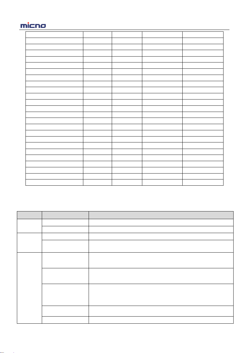
2.1 Product Inspection
Checking the following items when receiving the inverter
Confirmation Items Method
Confirm if the inverter is what you ordered Check name plate
Damaged or not Inspect the entire exterior of the inverter to see if
there are any scratches or other damage
resulting from shipping
Confirm if the fastening parts (screws, etc.)
are loose or not Check with a screw driver if necessary
User’s manual, certification and other spares User’s manual and the relative spares
Please contact the local agent or our company directly if there is any damage on the inverter.
2.2 Model Description
KE300A - 5R5G / 7R5P - T4
Sensorless vector
control inverter series
Power rating:
5R5: 5.5kW
7R5: 7.5kW
G/P:
Input voltage:
S2: 1AC 220~240V
T2: 3AC 220~240V
T4: 3AC 380~415V
T5: 3AC 440~525V
T6: 3AC 660~690V
G: Constant torque type
P: Variable torque type
Figure 2-1 Model description
2.3 Description of Nameplate
Figure 2-2 Nameplate
Model No.
Power rating
Input specification
Output specification
Bar code
KE300A Inverter Product Information
7
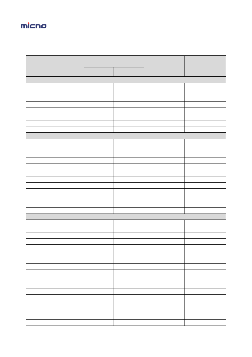
2.4 Selection Guide
Table 2-1 KE300A Series Inverter Model and Technical Data
Inverter Model Motor Rated Input
Current (A) Rated Output
Current (A)
kW HP
1AC 220~240V±15% input/output
KE300A-04-0R4G-S2
0.4
0.5
5.4
4
KE300A-04-0R7G-S2
0.75
1
8.2
7
KE300A-04-1R5G-S2
1.5
2
14
9.6
KE300A-04-2R2G-S2
2.2
3
23
17
KE300A-04-004G-S2
4.0
5
35
25
KE300A-04-5R5G-S2
5.5
7.5
45
32
KE300A-04-7R5G-S2
7.5
10
60
45
KE300A-04-011G-S2
11
15
80
60
1AC 220~240V±15% input / 3AC 220~240V±15% output
KE300A-0R4G-S2
0.4
0.5
5.4
2.3
KE300A-0R7G-S2
0.75
1
8.2
4
KE300A-1R5G-S2
1.5
2
14
7
KE300A-2R2G-S2
2.2
3
23
9.6
KE300A-004G-S2
4.0
5
40
17
KE300A-5R5G-S2
5.5
7.5
60
25
KE300A-7R5G-S2
7.5
10
75
32
KE300A-011G-S2
11
15
110
45
KE300A-015G-S2
15
20
140
60
KE300A-018G-S2
18.5
25
175
75
KE300A-022G-S2
22
30
210
90
KE300A-030G-S2
30
40
255
110
3AC 220~240V±15% input/output
KE300A-0R4G-T2
0.4
0.5
3.4
2.3
KE300A-0R7G-T2
0.75
1
5
4
KE300A-1R5G-T2
1.5
2
7.7
7
KE300A-2R2G-T2
2.2
3
13
9.6
KE300A-004G-T2
4.0
5
23
17
KE300A-5R5G-T2
5.5
7.5
35
25
KE300A-7R5G-T2
7.5
10
45
32
KE300A-011G-T2
11
15
60
45
KE300A-015G-T2
15
20
80
60
KE300A-018G-T2
18.5
25
100
75
KE300A-022G-T2
22
30
120
90
KE300A-030G-T2
30
40
150
110
KE300A-037G-T2
37
50
200
150
KE300A-045G-T2
45
60
240
176
KE300A-055G-T2
55
75
280
210
KE300A-075G-T2
75
100
410
304
KE300A-090G-T2
90
125
460
340

KE300A Inverter Product Information
8
KE300A-110G-T2
110
150
700
520
KE300A-132G-T2
132
175
790
585
KE300A-160G-T2
160
210
970
720
3AC 380~415V±15%
KE300A-0R7G/1R5P-T4
0.75/1.5
1/2
3.4/5
2.1/3.8
KE300A-1R5G/2R2P-T4
1.5/2.2
2/3
5/6.8
3.8/6
KE300A-2R2G/004P-T4
2.2/4.0
3/5
6.8/10
6/9
KE300A-004G/5R5P-T4
4.0/5.5
5/7.5
10/15
9/13
KE300A-5R5G/7R5P-T4
5.5/7.5
7.5/10
15/20
13/17
KE300A-7R5G/011P-T4
7.5/11
10/15
20/26
17/25
KE300A-011G/015P-T4
11/15
15/20
26/35
25/32
KE300A-015G/018P-T4
15/18.5
20/25
35/38
32/37
KE300A-018G/022P-T4
18.5/22
25/30
38/46
37/45
KE300A-022G/030P-T4
22/30
30/40
46/62
45/60
KE300A-030G/037P-T4
30/37
40/50
62/76
60/75
KE300A-037G/045P-T4
37/45
50/60
76/90
75/90
KE300A-045G/055P-T4
45/55
60/75
92/113
90/110
KE300A-055G/075P-T4
55/75
75/100
112/157
110/150
KE300A-075G/090P-T4
75/90
100/125
157/180
150/176
KE300A-090G/110P-T4
90/110
125/150
180/214
176/210
KE300A-110G/132P-T4
110/132
150/175
214/256
210/253
KE300A-132G/160P-T4
132/160
175/210
256/307
253/304
KE300A-160G/185P-T4
160/185
210/250
307/350
304/340
KE300A-185G/200P-T4
185/200
250/260
350/385
340/377
KE300A-200G/220P-T4
200/220
260/300
385/430
377/423
KE300A-220G/250P-T4
220/250
300/330
430/468
423/465
KE300A-250G/280P-T4
250/280
330/370
468/525
465/520
KE300A-280G/315P-T4
280/315
370/420
525/590
520/585
KE300A-315G/350P-T4
315/350
420/470
590/665
585/640
KE300A-350G/400P-T4
350/400
470/530
665/785
640/720
KE300A-400G/450P-T4
400/450
530/600
785/840
720/820
KE300A-450G/500P-T4
450/500
600/660
840/880
820/900
KE300A-500G/560P-T4
500/560
660/750
880/980
900/1000
KE300A-560G/630P-T4
560/630
750/840
980/1130
1000/1100
KE300A-630G/710P-T4
630/710
840/950
1130/1290
1100/1250
KE300A-710G-T4
710
950
1290
1250
KE300A-800G-T4
800
1070
1450
1400
KE300A-900G-T4
900
1200
1630
1580
KE300A-1000G-T4
1000
1330
1800
1750
KE300A-1200G-T4
1200
1600
2160
2100
KE300A-1400G-T4
1400
1860
2420
2350
3AC 660~690V±15%
KE300A-015G-T6
15
20
21
19
KE300A-018G-T6
18
25
28
22
KE300A-022G-T6
22
30
35
28
KE300A-030G-T6
37
40
40
35
KE300A-037G-T6
37
50
47
45
KE300A Inverter Product Information
9
KE300A-045G-T6
45
60
55
52
KE300A-055G-T6
55
75
65
63
KE300A-075G-T6
75
100
90
86
KE300A-090G-T6
90
105
100
98
KE300A-110G-T6
110
130
130
121
KE300A-132G-T6
132
175
170
150
KE300A-160G-T6
160
210
200
175
KE300A-185G-T6
185
250
210
195
KE300A-200G-T6
200
260
235
215
KE300A-220G-T6
220
300
257
245
KE300A-250G-T6
250
330
265
260
KE300A-280G-T6
280
370
305
300
KE300A-315G-T6
315
420
350
330
KE300A-350G-T6
350
470
382
374
KE300A-400G-T6
400
530
435
410
KE300A-450G-T6
450
600
490
465
KE300A-500G-T6
500
660
595
550
KE300A-630G-T6
630
840
700
680
KE300A-710G-T6
710
950
800
770
KE300A-800G-T6
800
1070
900
865
KE300A-900G-T6
900
1200
1000
970
KE300A-1000G-T6
1000
1330
1120
1080
KE300A-1200G-T6
1200
1600
1290
1280
KE300A-1400G-T6
1400
1860
1510
1460
KE300A-1600G-T6
1600
2130
1780
1720
2.5 Technical Specifications
Table 2-2 KE300A Series Inverter Technical Specifications
Item
Technical Index
Specification
Input Input voltage 1AC/3AC 220V±15%, 3AC 380V±15%, 3AC 660V±15%
Input frequency
47~63Hz
Output
Output voltage
0~rated input voltage
Output frequency V/f control: 0~3000Hz
Sensorless vector control: 0~300Hz
Control
Features
Control mode
V/f control
Sensorless vector control
Torque control
Operation command
mode
Keypad control
Terminal control
Serial communication control
Frequency setting
mode
Digital setting, analog setting, pulse frequency setting, serial
communication setting, multi-step speed setting & simple PLC, PID
setting, etc. These frequency settings can be combined & switched in
various modes.
Overload capacity
G model: 150% 60s, 180% 10s, 200% 3s
P model: 120% 60s, 150% 10s, 180% 3s
Starting torque 0.5Hz/150% (SVC); 1Hz/150% (V/f)

KE300A Inverter Product Information
10
Speed adjustment
range
1:100 (SVC), 1:50 (V/f)
Speed control
precision
±0.5% (SVC)
Carrier frequency
1.0--16.0kHz, automatically adjusted according to temperature and
load characteristics
Frequency accuracy
Digital setting: 0.01Hz
Analog setting: maximum frequency * 0.05%
Torque boost Automatically torque boost; manually torque boost: 0.1%~30.0%
V/f curve Three types: linear, multiple point and square type (1.2 power, 1.4
power, 1.6 power, 1.8 power, square)
Acceleration/decele
ration mode
Straight line/S curve; four kinds of acceleration/deceleration time,
range: 0.1s~3600.0s
DC braking DC braking when starting and stopping
DC braking frequency: 0.0Hz~maximum frequency, braking time:
0.0s~100.0s
Jog operation
Jog operation frequency: 0.0Hz~maximum frequency
Jog acceleration/deceleration time: 0.1s~3600.0s
Simple PLC &
multi-step speed
operation
It can realize a maximum of 16 segments speed running via the built-in
PLC or control terminal.
Built-in PID Built-in PID control to easily realize the close loop control of the
process parameters (such as pressure, temperature, flow, etc.)
Automatic voltage
regulation Keep output voltage constant automatically when input voltage
fluctuating
Control
Function
Common DC bus Common DC bus for several inverters, energy balanced automatically
Torque control Torque control without PG
Torque limit
“Rooter” characteristics, limit the torque automatically and prevent
frequent over-current tripping during the running process
Wobble frequency
control
Multiple triangular-wave frequency control, special for textile
Timing/length/
counting control
Timing/length/counting control function
Over-voltage &
over-current stall
control
Limit current & voltage automatically during the running process,
prevent frequent over-current & over-voltage tripping
Fault protection
function
Up to 30 fault protections including over-current, over-voltage,
under-voltage, overheating, default phase, overload, shortcut, etc., can
record the detailed running status during failure & has fault automatic
reset function
Input/out
put
terminals
Input terminals
Programmable DI: 7 on-off inputs, 1 high-speed pulse input
2 programmableAI: AI1: 0~10V or 0/4~20mA
A12: 0
~
10V or 0/4
~
20mA
Output terminals
1 programmable open collector output: 1 analog output (open collector
output or high-speed pulse output)
2 relay output
2 analog output: 0/4~20mA or 0~10V
Communication
terminals
Offer RS485 communication interface, support MODBUS-RTU
communication protocol
Human
machine LED display
Display frequency setting, output frequency, output voltage, output
current, etc.
KE300A Inverter Product Information
11
interface
Multifunction key
QUICK/JOG key, can be used as multifunction key
Environ-
ment
Ambient
temperature -10℃~40℃, derated 4% when the temperature rise by every 1℃
(40℃~50℃).
Humidity
90%RH or less (non-condensing)
Altitude
≤1000M: output rated power,
>
1000M: output derated
Storage
temperature
-20℃~60℃
2.6 External & Installation Dimensions
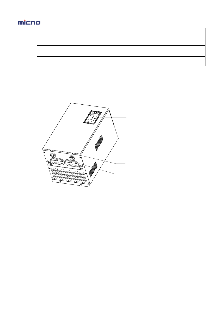
2.6.1 Parts Description
Operation keypad
Cover installation hole
Cables crossing
Inverter mounting hole
KE300A Inverter Product Information
12
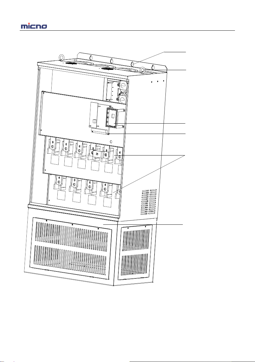
Figure 2-3 Parts of inverter
Inverter
hoisting hole
Inverter
mounting hole
Keypad bracket
Control board
Main circuit wiring
When installing a
cabinet, can outlet
f
ront, back, left
and right

KE300A Inverter Product Information
13
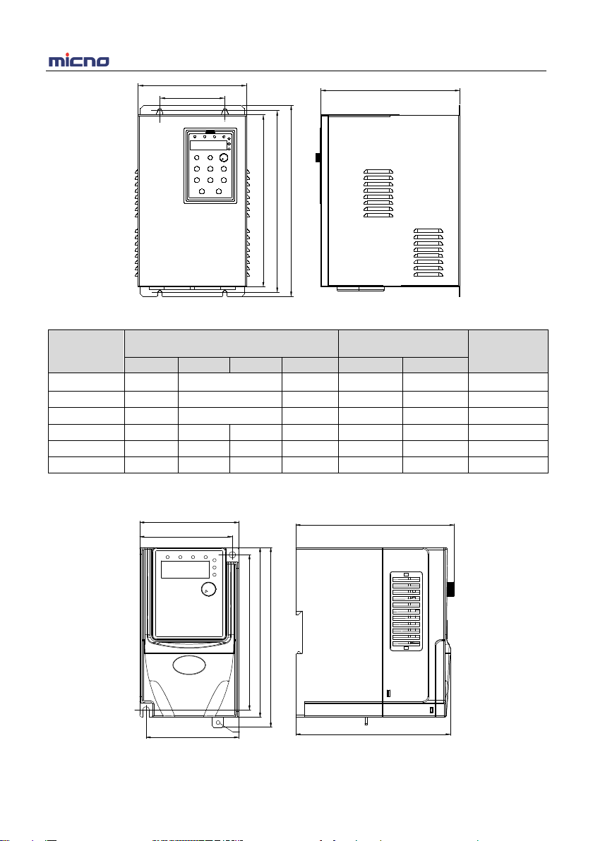
2.6.2 External & Installation Dimensions
1AC 220V output 0.4~11kW inverters dimension
0.4~1.5kW
50.00
A
W
B
H
D
2.2kW
50.00
78
73
73
128
140
M4
Grounding
124 .8
121 .8
148 .4
KE300A Inverter Product Information
14
W
H1
D
A
B
H2
4.0~11kW
Power
Range
External Dimension
( mm )
Installation Dimension
( mm )
Mounting
Bolt Model
W
H1
H2
D
A
B
0.4~1.5kW 78 148.4 124.8 73 128 M4
2.2kW
135
240
173
122.6
229
M4
4.0kW 170 285 176 158 273.5 M4
5.5kW
200
329.1
300
177.2
90
316.6
M4
7.5kW
225
397.6
365
185.2
120
384.1
M5
11kW
255
439.6
402.4
209.6
140
423.6
M5
1AC/3AC 220V 0.4~30kW inverters dimension
0.4~1.5kW
50.0
7
7
7
12
14
M
Groundin
124.
121.
148 .4

KE300A Inverter Product Information
15
50.00
A
W
B
H
D
2.2~4.0kW
W
H1
D
A
B
H2
5.5~15kW
W
A
H1
B
H2
D
18.5~30kW

KE300A Inverter Product Information
16
Power
Range
External Dimension
( mm )
Installation Dimension
( mm )
Mounting
Bolt Model
W
H1
H2
D
A
B
0.4~1.5kW 78 148.4 124.8 73 128 M4
2.2kW 110 185 153 98 174 M4
4.0kW
135
240
173
122.6
229
M4
5.5kW 170 285 176 158 273.5 M4
7.5kW
200
329.1
300
177.2
90
316.6
M4
11kW
225
397.6
365
185.2
120
384.1
M5
15kW
255
439.6
402.4
209.6
140
423.6
M5
18.5~22kW
280
570
521.2
258
190
552
M6
30kW
320
600
552
330
230
582
M8
3AC 220V 37kW and above inverters dimension
W
A
H1
B
H2
D
37~90kW

KE300A Inverter Product Information
17
W
H1
D
H2
110~160kW
Power
Range
External Dimension
( mm )
Installation Dimension
( mm )
Mounting
Bolt Model
W
H1
H2
D
A
B
37kW 320 600 552 330 230 582 M8
45~55kW 320 715 662 330 230 695.5 M8
75~90kW 480 790 725 385 360 768 M10
110~160kW 700 1390 1350 408 With base
This manual suits for next models
107
Table of contents
Other Micno Inverter manuals


