Italtecnica Sirio UNIVERSAL Owner's manual

EN
F
DE
E
Rel. 2.0 04/2020
Manuale di programmazione
Programming manual
Manuel de programmation
Programmieranleitung
Manual de programación
ǸțȒȖȊȖȌșȚȊȖȗȖȗȘȖȋȘȈȔȔȐȘȖȊȈȕȐȦ
IT
RUS
Sirio
PT
GR
CZ
SK
NL
Manual de programação
ƪDŽǒİLjǏǁįLjǎȺǏǎDŽǏĮNjNjĮIJLjıNjǎǘ
3URJUDPRYDFtSĜtUXþND
Návod na programovanie
Programmeerhandleiding
RO
Manual de programare
Universal

3

1.0 BAR
40Hz
1.0 BAR
Stand-by
V= 230V
I= 5.0A
Ti= 35° C
Ta= 35° C
Language
EN
PROGRAMMING (EN)
DDESCRIPTION OF THE BUTTONS
Left-hand arrow: this scrolls back through the menu pages
Right-hand arrow: this scrolls forwards through the menu pages
On-Off/Reset: this switches the device from stand-by to operation mode and resets the unit in the event
of alarms and/or errors.
³´EXWWRQWKLVLQFUHDVHVWKHYDOXHRIWKHSDUDPHWHUFXUUHQWO\VKRZQRQWKHGLVSOD\LWDOORZVWKHSXPSWRUXQDW
top speed without the dry running protection feature cutting in.
³-´EXWWRQWKLVGHFUHDVHVWKHYDOXHRIWKHSDUDPHWHUFXUUHQWO\VKRZQRQWKHGLVSOD\.
DMAIN MANU STRUCTURE
The main menu shows the operational values of the system: pressure, current frequency of the motor, input voltage, output current of the
motor and internal temperature of the inverter. It is also possible to select the language.
DDESCRIPTION OF THE PARAMETERS AND SCREEN PAGES
MAIN MENU:
These screen pages are accessible when the device is on.
Main screen page: when Sirio is operating correctly, the first line of the display shows the instantaneous
pressure detected by the system; the second line shows the current frequency of the motor. From here, it is
possible to scroll through the main menu using the arrows, or put the system in "Stand-by" by pressing the
central "on-off" key
When Sirio is in stand-E\WKHSXPSZLOOQRWVWDUWXSHYHQLIWKHSUHVVXUHGURSVEHORZWKH³3PLQ´YDOXHVHWTo
exit stand-E\SUHVVWKHFHQWUDOEXWWRQDJDLQ%\KROGLQJGRZQWKH³´EXWWRQWhe pump is brought up to the
maximum operating speed, overriding the dry running protection (use this function to fill the pump on initial
start-up).
Voltage and current screen: on this page of the menu it is possible to view the input voltage to the inverter and
the current absorbed by the motor. The value of the output current to the motor may differ from the value of the
input current as the inverter modulates both frequency and voltage.
Temperature screen: this displays the ambient temperatures inside the inverter and the IGBT power module.
The values of these temperatures contribute to the intelligent power management which limits the value of the
maximum frequency of the motor when the pre-alarm thresholds are reached.
Language: The language used for the menus and the alarm messages can be selected by the user. Use the + and
±buttons to alter the parameter setting.
1.0 BAR
40Hz
V= 230V
I= 5.0A
Ti= 35° C
Ta= 35° C
Language
EN

Pmax
3.0 BAR
Dp.start
0.5 BAR
P.dr.ru.
0.5 BAR
Pmax2
9.0 BAR
Dp.stop
0.5 BAR
Unit
BAR
Imax
0.5 Amp
Rotat.
-->
P.Limit
9.0 BAR
Min.fre.
25Hz
Stop fr
30 Hz
INSTALLER PARAMETERS:
These parameters can be found on hidden pages and usually they should only be changed in the installation phase. To access these pages
switch the device to Stand-E\DQGNHHSWKH³´DQG³-³EXWWRQVSUHVVHGGRZQWRJHWKHUIRUVHFRQGV2QFH\RXKDYHHQWHUHGWKHKLGGHQPHQXuse the³´DQG³!!´EXWWRQVWRVFUROOWKHSDJHVDQGWKH³´DQG³-³EXWWRQVWRFKDQge the parameters. To return to the main page press the
button in the centre. Some parameters may not be displayed if the relative function is not enabled.
Pmax: this parameter enables entry of the set-point value of the device. It is a constant pressure value required
by the system (maximum pressure). During its operation Sirio regulates the revs of the electric pump to adapt
them to the actual required flow-rate, therefore maintaining the constant pressure of the system. When it is
necessary to set the Pmax to a value higher than the maximum pump head, motor shut down on valve closure is
only guaranteed if the flow switch is activated, as Sirio switches off the pump when the flow of water passing
through it falls below the minimum values (approx. 2 litres/minute) irrespective of the pressure reached in the system.
Delta P start-up: this parameter sets the delta negative of pressure compared to Pmax for the start-up of the
pump. On opening of any type of utility, the pump will not start-up until the system pressure has fallen below
Pmax by a value equal to the delta set in this parameter. After the motor is started up, the operating rotation
speed is controlled to maintain the pressure value as close as possible to that set in the parameter Pmax. The
minimum differential settable between Pmax and Pmin is 0.3 Bar, with the recommended value being at least 0.5 Bar.
Dry-running pressure: this parameter only affects operation with the flow switch deactivated. Define the
minimum pressure value below which, with the motor at maximum frequency, the protection against dry-
running triggers.
Pressure limit: this parameter sets the threshold for the overpressure protection intervention.
The overpressure protection intervention stops the inverter until the user resets it.
Pmax2: this parameter enables entry of the secondary set-point of the device. When the auxiliary contact (or the
auxiliary I/O board input) is closed externally, the pressure value set in Pmax2 becomes the new set-point,
according to which Sirio regulates the revs of the electric pump.
Delta P stop: this parameter sets the positive pressure delta compared to Pmax for immediate shutdown of the
pump. During normal operation, when the valves close, the pump stops after a time set in the parameter "stop
delay". In any case, if the system pressure exceeds the Pmax value of a delta greater than that set in this
parameter, the pump will stop immediately to avoid overpressure which may damage the system.
Unit of measurement: select the unit of measurement in BAR or PSI
Imax: this parameter enables entry of the maximum current absorbed by the electric pump in routine
conditions, to enable shut-down of the motor in the event of excessive absorption. The motor is also shut down
if the current read during operation is below 0.5 A following interruption of the connection between the motor
and Sirio. The trip time of the current overload safety device is inversely proportional to the entity of the
overload in progress; therefore a slight overload will lead to a more delayed trip time while a more significant
overload will accelerate the trip time. On activation of the device, if the Imax parameter is set at 0.5 A (factory setting), the display
automatically shows the settings page of the maximum current and no action is permitted until the absorption limit value is set.
Rotation direction (only for three-phase pump version): this screen enables the user to invert the direction of
rotation of the electric pump without modification to the electric motor wiring. To modify the direction of
rotation of the motor, use buttons "+" and "-"; the direction indicated by the arrow has a purely indicative value
and does not reflect the actual sense of rotation which must be verified by the installer.
Minimum frequency: this parameter defines the minimum frequency at which the pump starts up and stops.
For three-phase pumps a value of 25Hz is advised, for single-phase pumps 30Hz.Also consult the information
supplied by the manufacturer of the electric pump to determine at what minimum frequency value the connected
electric motor can operate
Stop frequency: only during operation without the flow switch, this parameter determines the minimum
frequency value below which the motor will stop. During adjustment, if the Pmax pressure value is reached and
the frequency of the motor is below this value, the inverter will attempt to stop the motor. If all the utilities are
closed and the pressure remains constant the pump will stop correctly. If the pump does not stop, try to increase
this value. By contrast, if the pump carries out continuous start-up and stop cycles, try to lower the stop
frequency value.

Nom.fre.
50 Hz
Swit.fr.
5kHz
Fre.cor.
0Hz
S.Start
ON
Flow.se
ON
Command
PRES
Aux.con
1<->
I/O in.
OFF
Pump
1X230V
Nominal motor frequency: depending on which motor is used, it is possible to select a maximum nominal
output frequency from the inverter (50 or 60 Hz). Caution: an incorrect selection of the maximum frequency
may cause damage to the pump; consult the manufacturer's technical data carefully.
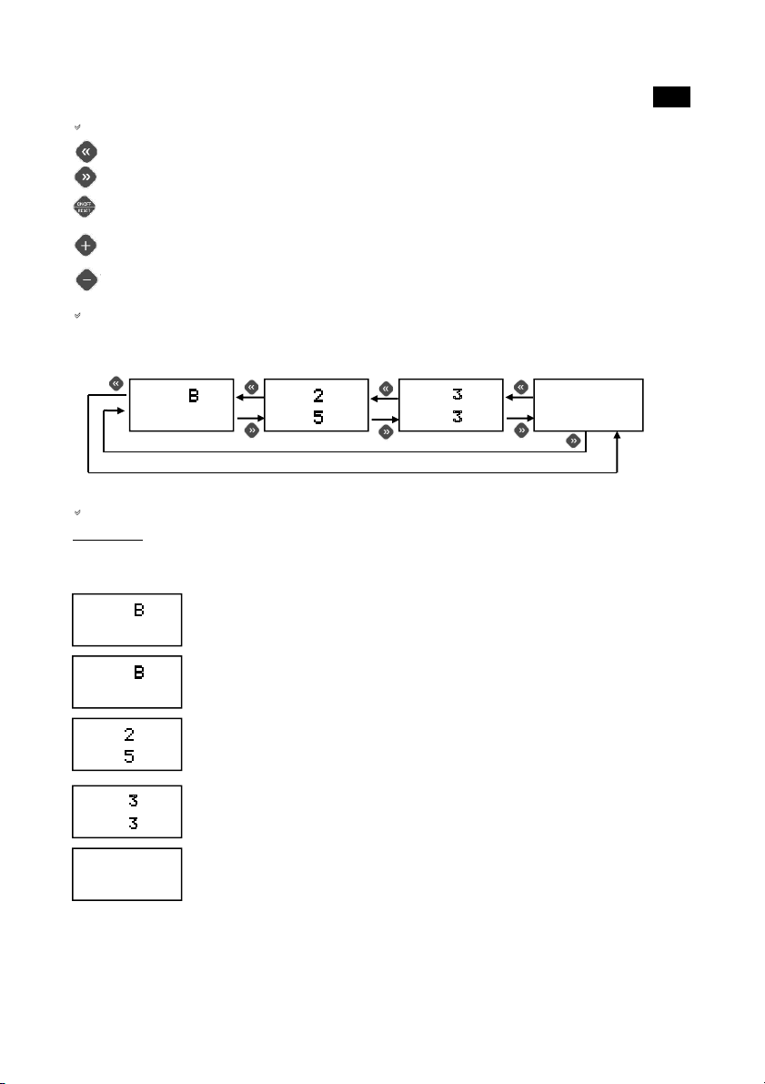
Switching frequency: set the frequency of inverter switching. The selectable values are 3, 5 and 10 kHz.
Higher switching frequency values may reduce the noise of the inverter and allow a more fluid regulation of the
motor but may cause increased temperatures in the electronic board, an increase in electromagnetic disturbances
and potential damage to the electric motor (especially with long cables). Low switching frequency values are
recommended for medium-large pumps, where there is a long distance between the inverter and motor or high
ambient temperatures.
Frequency correction: this parameter enables entry of a deviation, positive or negative, of the maximum
requency compared to the set nominal value. It may be useful to set a negative deviation (up to ±5Hz) where a
limit to the maximum power of the electric pump is wanted and to avoid possible overload. A positive increase
(up to +5Hz) may instead be necessary when a slightly higher electric pump performance is needed. While no
particular precautions exist in lowering the maximum frequency, its increase must be carefully evaluated after having consulted the
manufacturer of the electric pump and taking into consideration the maximum current supported by the inverter.
Soft-Start (progressive start-up): This screen enables the user to activate or deactivate "soft-start" function.
When this function is active the pump starts up progressively; by contrast, the start-up is always at maximum
revs for a period of 1 second before the adjustment of revs begins.
Pump type: set the type of the pump connected to Sirio, single phase with starting capacitor (1 X 230V) or
three-phase with delta connection (3 X 230V).
Flow sensor: this activates or deactivates operation of the integrated flow switch. The factory setting of the
flow switch is active, so that the pump will stop when the valves close, detecting a zeroing of the flow through
the inverter. The same principle is used for the protection against dry-running. In any case, conditions may
occur (for example, the use of not perfectly clean water) which could impair correct operation of the flow
switch preventing the pump from stopping correctly. In these conditions, it is possible to deactivate the flow
switch and operate the Sirio exclusively on the basis of pressure and frequency information. In this case it is essential to correctly regulate
the parameters of the stop frequency and dry-running pressure for efficient operation of the inverter. Furthermore, when the flow switch is
deactivated, it is necessary to install an expansion tank immediately after the Sirio to help regulate the pressure in the stop phase and avoid
continuous restarts of the pump, taking care to periodically check the pre-load values.
Command origin: selects the command source. If the parameter is set to pressure, the operation is regulated
automatically based on the system pressure. Otherwise, if set to manual mode, it is possible to manually
command start-up, stop and the speed of the electric pump directly via the keyboard. Caution: in manual mode,
the dry-running and pressure limitation protections are not active. This mode should only be used temporarily
and under the direct control of a person. Pay maximum attention during these operations!
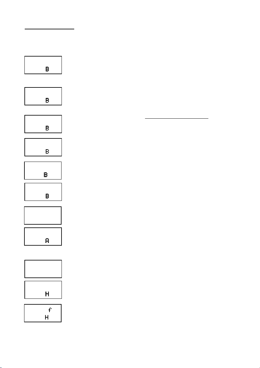
Auxiliary contact: use this parameter to select the function to be associated with the auxiliary contact; the
settable values are as follows:
³-!´WKHDX[LOLDU\FRQWDFWis used for the connection of two Sirio devices in a twin pressurisation unit (factory
settings)
³-³WKHDX[LOLDU\FRQWDFWLVXVHGWRUHPRWHFRQWUROWKHVWDUWVWRSRIWKHPRWRUSXPS
³;´WKHDX[LOLDU\FRQWDFWLVXVHGWRFRQWURODVHFRQGSUHVVXUHVHW-point (Pmax2).
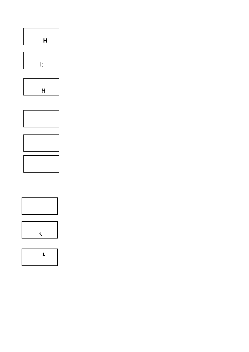
Input function on the I/O board: determines the function associated with the digital input of the auxiliary I/O
board (available on request).
The settable values are:
³2))³input disabled
³(55´error signal: on closure of the auxiliary input, the pump will immediately shut down and "External error" will appear on the screen.
Use this function if it is necessary to stop the inverter due to an external error.
³-³the auxiliary input is used for remote control of start-up and shut-down of the electric pump; if the same setting is also active for the
parameter "Aux. Con", it is necessary to close both contacts to start the motor (AND logic)
³;´the auxiliary input is used to control a second pressure set-point (Pmax2); the auxiliary input is used to control a second pressure set-
point (maxP2); if the same setting is also active for the parameter "Aux. Con", it is necessary to close one of the two contacts to control the
second set-point (OR logic).

I/O out
OFF
Stop.del
10.0sec
Reset
15 min
Reset
5test
Reset
Full.OFF
Input function on the I/O board: choose the function associated to the digital input of the auxiliary I/O board
(available on request).
The settable values are:
³2))³output disabled
³(55³error: the output is activated (closed contact) in the presence of any error in Sirio
³321³pump in operation: the output is activated (contact closed) whenever Sirio controls the pump start-up
³$8;´auxiliary pump: enables control of an auxiliary pump at a set speed which starts up when the pump controlled by Sirio is no longer
able to fulfil the needs of the system. The output is activated (closed contact) when the frequency of the pump is at the maximum admissible
value and the pressure drops below the minimum start-up value. Caution: it is not possible to connect a load superior to 0.3° to the output
relay! Consult the documentation supplied with the I/O auxiliary board for the correct connection to an external control panel.
Delay on stop: this parameter enables the user to set after how many seconds the electric pump is stopped
following the closure of all utilities. If continuous start-up and stop of the pump is detected with low flows,
increase the delay before stopping to make operation more uniform. It may be useful to increase this parameter
also to avoid excessively frequent intervention of the dry-running protection, especially in submerged pumps or
on those with problems in self-priming. The factory setting is 10 seconds.
Auto-reset-interval: during operation of the electric pump if a temporary absence of water on intake is
detected, Sirio will shut off power to the motor to avoid it being damaged. On this screen it is possible to set
how many minutes the device will remain stopped before carrying out an automatic restart to check for the
availability of water on intake. If the attempt is successful, Sirio will automatically exit from the error condition
and the system resumes normal operation; if this is not the case, another attempt be will be carried out after the
same time interval. The maximum settable interval is 240 minutes (recommended value is 60 min).
Auto-reset test n.: this parameter sets the number of attempts that Sirio will perform to resolve a stop condition
due to dry running. Once thLVOLPLWKDVEHHQH[FHHGHGWKHV\VWHPVKXWVGRZQDQGWKHXVHU¶VLQWHUYHQWLRQLVrequired. If this value is set to zero, the auto-reset function is switched off. The maximum number of attempts
allowed is 20. Use buttons + and ±to modify the parameter value.
Total automatic reset: when set to ON, the automatic reset function is active for any error, in addition to dry-
running, detected by the system. Caution: the automatic and uncontrolled reset of some errors (for example,
overload) could over time cause damage to the system and to Sirio. Always take great care when using this
function.

ADVANCED PARAMETERS:
The advanced parameters are accessible only to the technical assistance service. For access to these parameters, it is necessary to contact the
re-seller, a technical assistance centre or the manufacturer.
The following table lists the advanced parameters for reference when technical assistance is required.
REF.
PARAMETER
DESCRIPTION
3.0
Pressure calibration 0.0 Bar
To carry out calibration of the pressure sensor at 0 Bar
3.1
Pressure calibration 5.0 Bar
To carry out calibration of the pressure sensor at 5 Bar
3.2
Flow sensor calibration
To carry out calibration of the flow sensor
3.3
Pressure test
Current pressure test signal
3.4
Flow switch test
Flow switch test signal
3.5
Software Release
Release of software
3.6
Power supply timing
Inverter power supply timer
3.7
Pump timing
Electric pump operational timer
3.8
Last error
Last error occurred log
3.9
Start-up
Pump start-up counter
4.0
Vboost
Voltage boost at 0Hz
4.1
Dry run
Time delay before activation of the protection due to no water
4.2
Protection starts per hour
Activation or deactivation of the control on the number of start-ups per hour (leak
checks)
4.3
Anti-blockage protection
Activation or deactivation of a function that automatically starts up the pump after 24
hours of disuse
4.4
Dead time PWM
Dead time PWM setting
4.5
Ki
PID controller integral constant
4.6
Kp
PID controller proportional constant
4.7
Boost time
Boost time at maximum frequency with soft start disabled
5.0
Ta max
Maximum ambient temperature
5.1
Tm max
IGBT module maximum temperature
5.2
Ta reduction index
Frequency reduction index on ambient temperature
5.3
Tm reduction index
Frequency reduction index on module temperature
5.6
Minimum voltage
Minimum power supply voltage threshold
5.7
Maximum voltage
Maximum power supply voltage threshold
5.9
Debug Variable
Debug variable selection for process value display

E0 ( 0)
Lo.Volt
E1 ( 0)
Hi.Volt
E2 ( 0)
Shortcir
E3 ( 0)
Dry run
E4 ( 0)
Amb.Temp
E5 ( 0)
IGBTtemp
E6 ( 0)
Overload
E8 ( 0)
Ser.Err.
E9 ( 0)
Ov.Pres
E10( 0)
Ext.Err
E11( 0)
Start/H
E12( 0)
Err.12V
E13( 0)
Pres.Sen
DALARMS
In the event of system anomalies or malfunctions, one of the following screens will appear on the Sirio display. Each error is coded with the
letter "E" followed by a number from 0 to 13. The number which appears in brackets represents the number of recurrences of each error. To
reset an alarm, after having resolved the cause, it is usually sufficient to press the central "reset" key or interrupt the electrical power supply
for a few seconds.
E0 ±Low voltage: indicates that the power supply voltage is too low. Check the input voltage value
E1 ±High voltage indicates that the power supply voltage is too high. Check the input voltage value
E2-Short Circuit: This message will appear on the screen when a short circuit is detected at the inverter output;
this may occur following incorrect connections of the electric motor, damage to the electrical insulation in the
wires which connect the electric pump to the device or a fault in the pump's electric motor. When this error
appears the electrical system should be checked as soon as possible by specialised personnel. The error may only
be removed by disconnecting the equipment from the electrical power source and resolving the cause of the fault. Attempting to restart the
inverter in the presence of a short-circuit in output may cause serious damage to the equipment and be a source of danger to the user.
E3-Dry running: this message appears when the system is stopped following a pump intake water shortage. If
the auto-reset function has been enabled, the Sirio will carry out automatic attempts to check for the availability
of water7RFOHDUWKHHUURUVWDWXVSUHVVWKHFHQWUDO³UHVHW´EXWWRQ
E4- Ambient temperature: the error appears if the maximum internal ambient temperature of the inverter is
exceeded. Check the conditions of operation of the inverter.
E5-module temperature: the error appears if the maximum temperature of the IGBT module of the inverter is
exceeded. Check inverter operating conditions, in particular the water temperature and the current absorbed by
the pump.
E6-Overload: this alarm is displayed when electric pump absorption exceeds the maximum set current as
entered in the Imax value: this may occur following intensive use of the electric pump, continuous restarts at
close intervals, problems with the motor windings, or following problems with the electrical connection between
the motor and Sirio. If this alarm trips frequently, arrange for the system to be checked by the installer.
E8-Serial error: this alarm may occur where there is an internal serial communication on Sirio. Contact the
technical assistance.
E9-Pressure limit: the alarm intervenes when the maximum set pressure threshold has been exceeded. If the error
appears repeatedly, check the setting of the "P limit" parameter. Also check other conditions which may have
caused an overpressure (for example, partial freezing of the fluid).
E10- External error: this alarm will be displayed if, after having set the external error function on the auxiliary
I/O board, the I/O input contact is closed.
E11-Number of maximum starts/hour: this error appears if the maximum number of admissible start-ups per
hour has been exceeded. Check for the presence of any leaks in the system. Check the pre-loading of any installed
tanks.
E12- Error 12V: an anomaly has been detected in the internal low voltage power supply circuit. Have the
manufacturer check the device.
E13- Pressure sensor error: the pressure sensor has detected an incorrect value. Have the manufacturer check
the device.

VPOSSIBLE MALFUNCTIONS:
DWhen one of the taps / outlets in the system is opened, the pump does not start, or there is a few seconds delay before it starts
The DeltaP value is set too high or a check valve has been fitted downstream of the device. Try to increase the value of the start-up pressure
Pmin and eliminate any valves after the Sirio. Ensure correct operation of the external enabling contact.
DWhen the taps / outlets are closed, the pump stops but restarts a few seconds later and there is no leakage from the system
'SVWDUW´YDOXHLVWRRORZLQFUHDVHLW
DThe pump keeps switching on and off
There is leakage in the system. Check the various hydraulic connections. Check the display for pressure drops when the taps are closed.
Check the Sirio's check valve for dirt which could be preventing it from closing properly and, if necessary, clean it with compressed air.
DThe device often signals 'dry running'
The pump intake pipe drains when the system is not used for some time, thereby preventing it priming the next time it is started. If there is a
foot valve fitted, check its seal.
DThe device often signals 'high or low voltage'
The power supply voltage may not comply with the device specifications; have it checked by qualified personnel.
DThe device overheats and the over-temperature protection intervenes
The inverter no longer exchanges heat with the water that runs through the device or the temperature of the fluid pumped is too high; check
for foreign bodies that block the flow of water and if necessary have the device checked by the manufacturer.
DWhen the water flow is extremely low, the pump does not operate normally
The flow values are too low and as the device is unable to detect them, it shuts down the motor pump. Fit a small surge tank (1-2 litres) in the
system to give it more flexibility and reduce the number of restarts.
DThe pump does not stop
There is substantial leakage in the system or the check valve on the device is jammed by dirt; try moving the check valve with your fingers
and checking that the spring can maintain the seal.
The sensor which detects the valve position is broken. Have the device checked by the manufacturer.
DThe pump is running at top speed but performance levels are low
The pump or the capacitor connection is not correct: check the electric wiring.
The pump runs in the opposite direction (three-phase model); check rotation direction.
The pump is damaged or there is foreign matter clogging the waterway.
DWhen more water is required of the system, the pressure drops
This is a normal condition which is due to the fact that the device is unable to force the pump above its capacity curve. As a result, once a
certain capacity is reached, the pressure is no longer offset as the pump is already running at the highest number of revolutions allowed. In
these cases, a pump with higher performance levels should be installed.

#MAINTENANCE:
The Sirio is designed to keep maintenance requirements at a minimum. To guarantee the device a long working life and perfect functionality,
always follow the instructions below:
- ensure the device does not have to withstand temperatures of below 3° C; if this is not possible, make sure all the water inside it is drained
out to prevent it from freeziQJXSDQGGDPDJLQJWKHGHYLFH¶VSODVWLFERG\
- if the pump is equipped with intake filters, carry out regular checks to ensure they are clean;
- always ensure that the cover is closed properly and the cable conduit is tightto prevent water from penetrating from outside;
- switch off the power supply and drain the water from the system when it is going to be left unused for some time;
- do not force the pump to run without intake water, as this could damage both the pump and the Sirio;
- before using the device with any other liquids than water, contact the manufacturer.
- do not carry out any operations when the device is open
- wait 3 minutes before removing the cover from the device so the condensers can discharge.
WARNING: this device does not contain any parts that can be repaired or replaced by the end user. You are thereforeadvised
not to remove the electronic card's protective cover as this would lead to forfeiture of the guarantee!
Other manuals for Sirio UNIVERSAL
2
Table of contents
Other Italtecnica Inverter manuals
Popular Inverter manuals by other brands

MULTIQUIP
MULTIQUIP Power WHISPERWATT DCA-45SSIU2 Parts and operation manual

Phocos
Phocos Any-Grid Series Setup guide

Huawei
Huawei SUN2000-2KTL-L0 quick guide

SEG SOLAR
SEG SOLAR SEG-6PA-XXXWW installation guide

Deger Energie
Deger Energie DEGERtraker 3000NT Assembly instruction

Leroy-Somer
Leroy-Somer POWERDRIVE MD Commissioning manual

Chicago Electric
Chicago Electric 54516 operating instructions

Westinghouse
Westinghouse 5300 Running Watts user manual

GUANGDONG EAST POWER
GUANGDONG EAST POWER EA-IVS6000 Series user manual

Daikin
Daikin FTXN25MV1B installation manual

Agilent Technologies
Agilent Technologies 33120A quick guide

ASTRO
ASTRO VG-870 instruction manual