Installation Manual 501.5 Series 5000
Unirac, Inc.
www.unirac.com
1411BroadwayBoulevardNE
AlbuquerqueNM87102-1545USA
505.242.6411
505.242.6412Fax
Page
4
10yearlimitedProductWarranty
Unirac, Inc., warrants to the original purchaser
(“Purchaser”) of product(s) that it manufactures
(“Product”) at the original installation site that
the Product shall be free from defects in material
and workmanship for a period of ten (10) years,
from the earlier of 1) the date the installation
of the Product is completed, or 2) 30 days after
the purchase of the Product by the original
Purchaser.This Warranty does not cover damage
to the Product that occurs during its shipment,
storage, or installation.
This Warranty shall be VOID if installation of
the Product is not performed in accordance
with Unirac’s written installation instructions, or
if the Product has been modified, repaired, or
reworked in a manner not previously authorized
by Unirac IN WRITING, or if the Product is
installed in an environment for which it was
not designed. Unirac shall not be liable for
consequential, contingent or incidental damages
arising out of the use of the Product by the
Purchaser under any circumstances.
If within the specified Warranty period the
Product shall be reasonably proven to be
defective, then Unirac shall repair or replace the
defective Product, or any part thereof, in Unirac’s
sole discretion. Such repair or replacement shall
completely satisfy and discharge all of Unirac’s
liability with respect to this limited Warranty.
Under no circumstances shall Unirac be liable
for special, indirect or consequential damages
arising out of or related to use by Purchaser of
the Product.
Manufacturers of related items, such as PV
modules and flashings, may provide written
warranties of their own. Unirac’s limited
Warranty covers only its Product, and not any
related items.
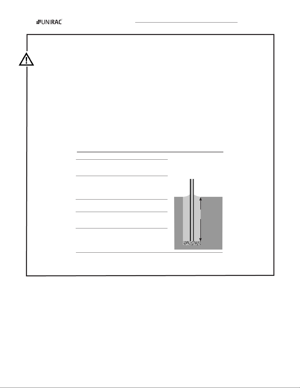
Final adjustments
Once the rack/PV module assembly is attached to the pole,
raise and rotate the assembly as needed. Never let the as-
semblyslidedownthepole. Tighten the flange nuts on the
U-bolt and channel bracket bolts. Then tilt the rails to bring
the module to the desired angle. Tighten the bracket/rail and
module.
If desired, install the self-tapping screws to permanently
fix the angle of the rack/PV module assembly.
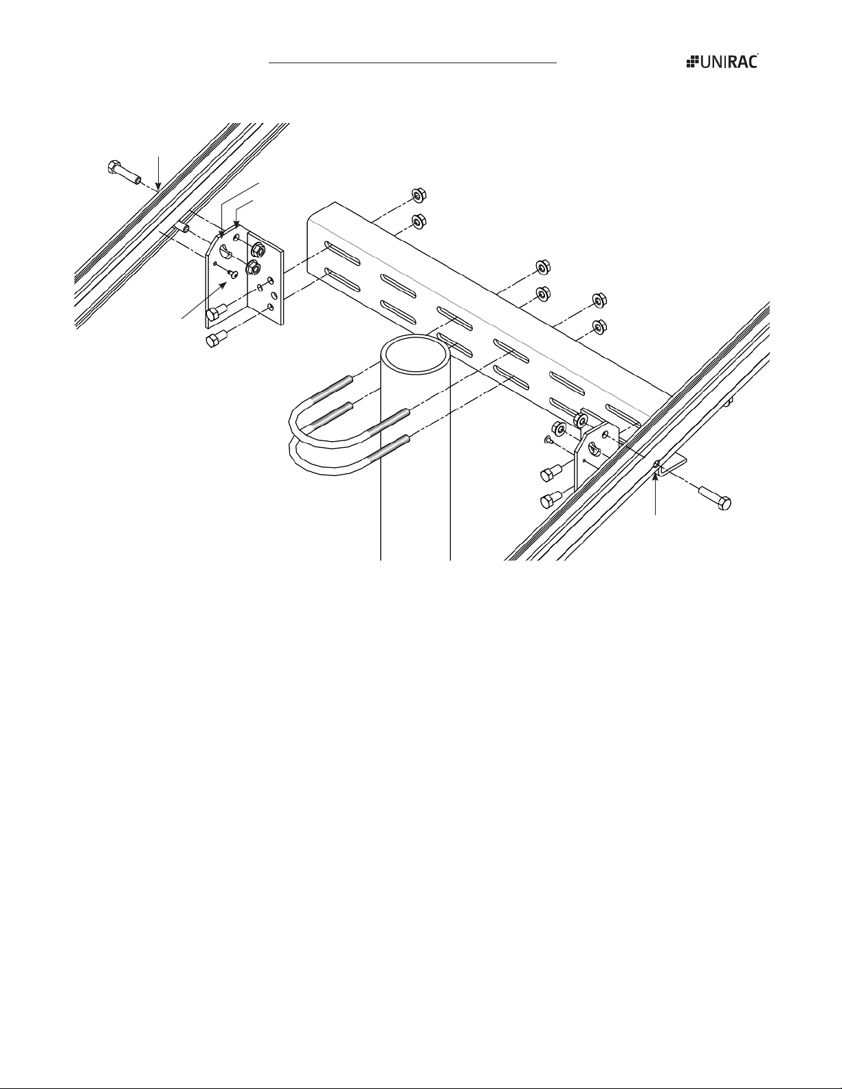
Module attachment
Attach the PV module to the rack using clips and ¼-inch hard-
ware. Be sure to center the module on the channel. If channel
slotsdonotallowcorrectspacingandcentering:(1)movethe
clips to the other side of the rails, (2) reverse the brackets, or
(3) move the rails to the other side of the brackets.
PV module
SolarMount
heavy-duty rail
(cross section)
Module
mounting clip
Flat Washer: Most PV modules have mounting holes small enough
to secure the module bolt without the washer. Use the washer
with larger holes. If in doubt, use the washer.
Module bolt
Flange
nut
Module
mounting hole
Opposite clip
slot employed