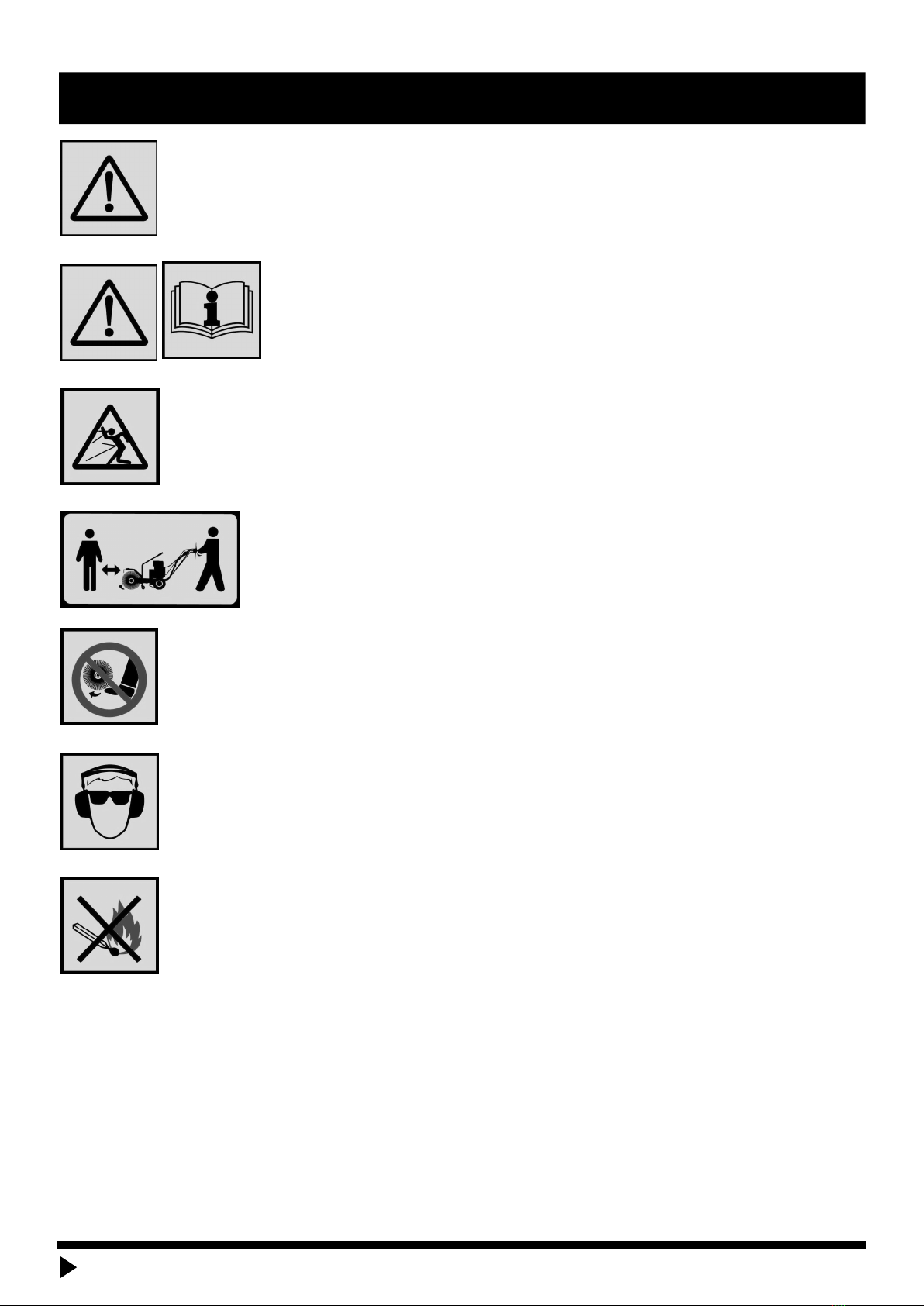
WARNING
READ MANUAL PRIOR TO INSTALL
Improper installation, operation, or maintenance of this equipment could result in serious injury or death. operators and
maintenance personnel should read this manual as well as all manuals related to this equipment and the prime mover thoroughly
before beginning installation, operation, or maintenance. Follow all Safety instructions in This manual and the prime Movers
manual.
WARNING
READ AND UNDERSTAND ALL SAFETY STATEMENTS
Read all safety decals and safety statements in all manuals prior to operating or working on this equipment. Know and obey all
regulations, local laws and other professional guidelines for your operation. Know and follow good work practices when
assembling, maintaining, repairing, mounting, removing or operating this equipment.
WARNING
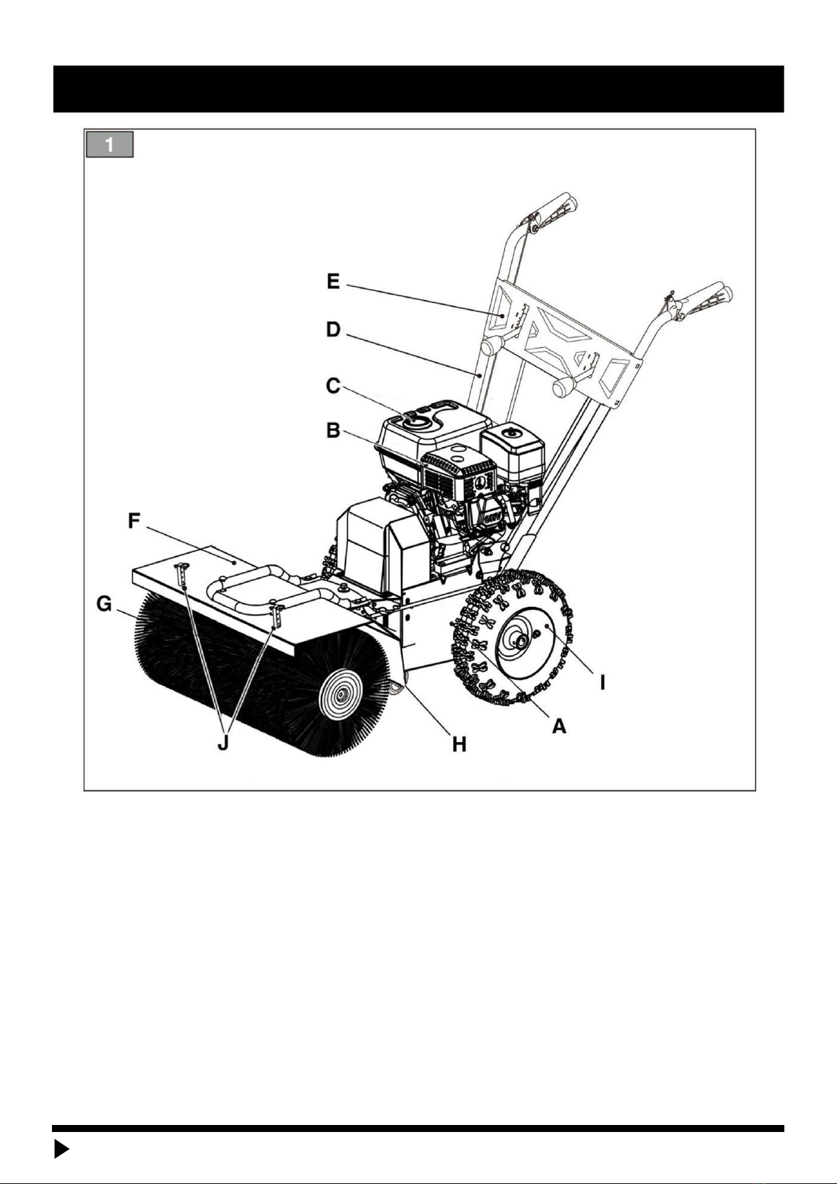
KNOW YOUR EQUIPMENT
Know your equipment’s capabilities, dimensions and operations before operating. Visually inspect your equipment before you
start, and never operate equipment that is not in proper working order with all safety devices intact. Check all hardware to assure
it is tight. Make certain that all locking pins, latches, and connection devices are properly installed and secured. Remove and
replace any damaged, fatigued or excessively worn parts. Make certain all safety decals are in place and are legible. Keep decals
clean, and replace them if they become worn and hard to read.
WARNING
PROTECT AGAINST FLYING DEBRIS
Always wear proper safety glasses, goggles or a face shield when driving pins in or out or when operation causes dust, flying
debris, or any other hazardous material.
WARNING
LOWER OR SUPPORT RAISED EQUIPMENT
Do not work under raised booms without supporting them. Do not use support material made of concrete blocks, logs, buckets,
barrels or any other material that could suddenly collapse or shift positions. Make sure support material is solid, not decayed,
warped, twisted, or tapered. Lower booms to ground level or onto blocks. Lower booms and attachments to the ground before
leaving the cab or operator’s station.
WARNING
DO NOT MODIFY MACHINE OR ATTACHMENTS
Modifications may weaken the integrity of the attachment and may impair the function, safety, life and performance of the
attachment.when making repairs, use only the manufacturer’s genuine parts, following authorized instructions. other parts may
be substandard in fit and quality. Never modify any RoPS (Roll over Protection System) equipment or device. Any modifications
must be authorized in writing by the manufacturer.
GENERAL SAFETY PRECAUTIONS
www.tmgindustrial.com 5/22 TOLL FREE:1-877-761-2819