1.Precautions for safe operation
Read the operating instructions of the machine carefully, and be familiar with the performance and how
to operate all the control devices!
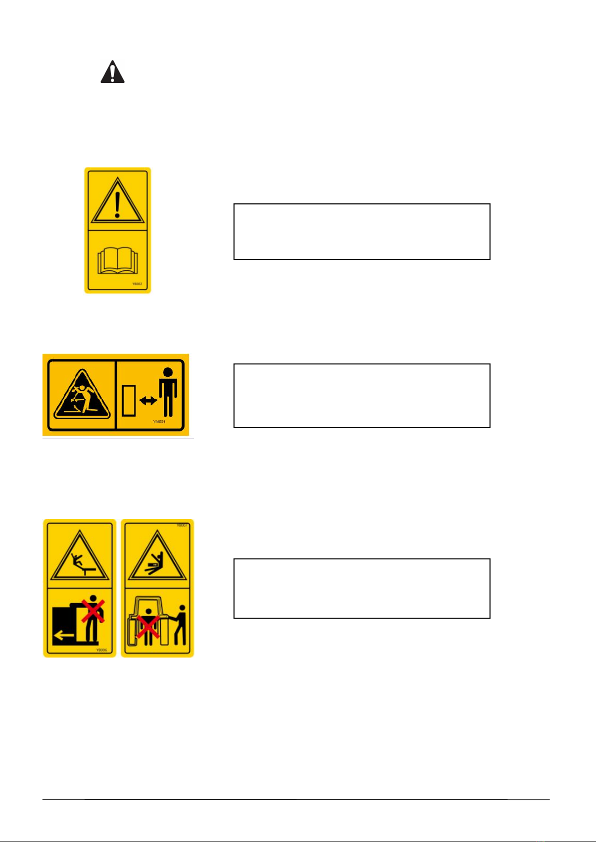
Understand all the safety labels on the equipment, and keep the labels clean. Please do not paint or
move any safety labels casually. If they are damaged, they should be replaced immediately!
A warning sign should be set up in the work area where the operator is to tell others not to approach
it to prevent splashing!
Do not clean up close to people, buildings, vehicles or other objects that may be damaged by flying
debris!
Notice! Failure to follow this warning may cause injury.
Preparations before operation
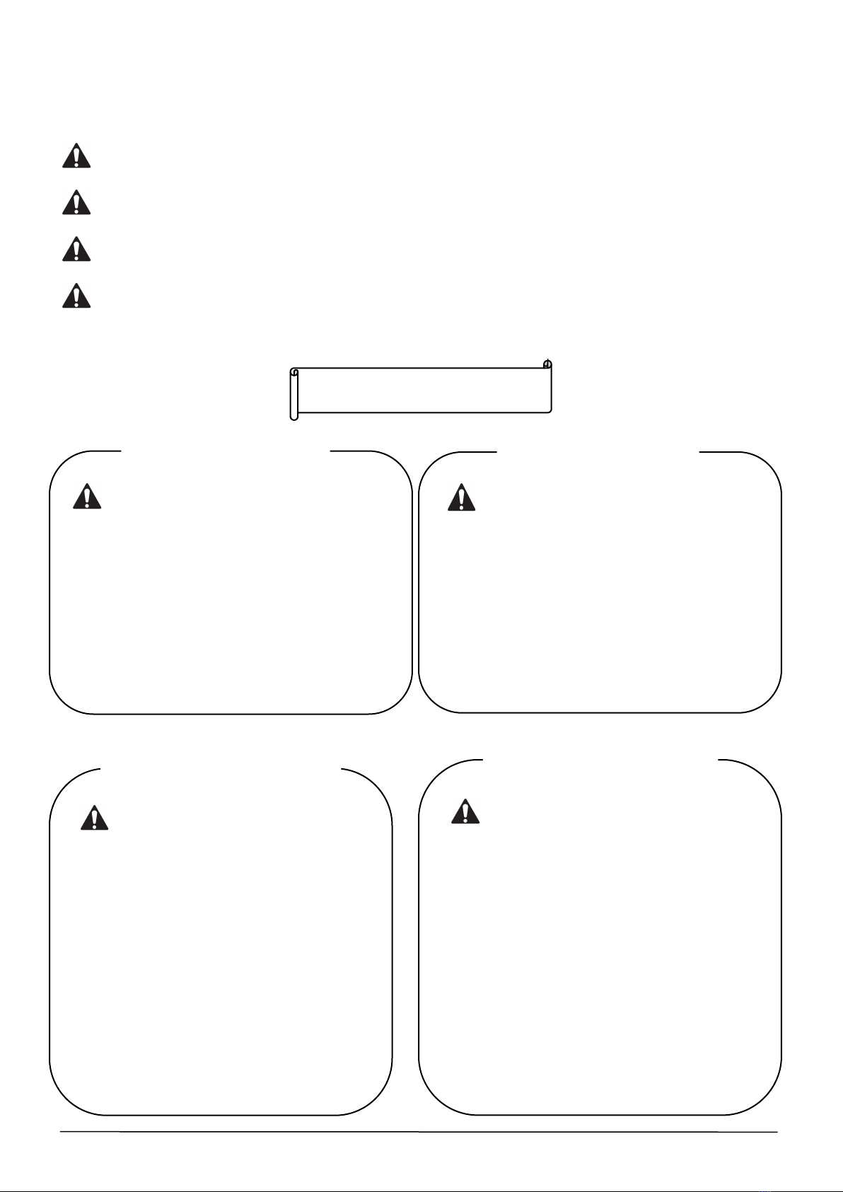
NOTICE !
★If you do not know how to operate the
machine, because the instruction manual is not
placed around the product, if you use your own
judgment to deal with it, unexpected accidents
may occur and cause injuries. Make sure that
the instruction manual is kept around the
product, and you can read it at any time when
you don't know how to use it.
Place the instruction manual
around the product
WARNING !
★If you wear inappropriate clothing to
operate the machine, a part of the clothing will
be caught by the machine and cause injury. In
severe cases, a major fatal accident may
occur.
Please operate according to the clothes
suggested below:
● Do not wear oversized tops and pants.
● The sleeves and hem should not be too fat.
● Wear a safety helmet.
Do not wear banded or flocculent items such
as turbans or towels on the head and waist.
Clothing selection during operation
NOTICE !
★If you do not fully understand the safety
precautions and use essentials described in the
instruction manual, unexpected accidents may
occur. before operation, please fully understand
the warning signs affixed to the product, the
safety precautions and the essentials in the
instruction manual before proceeding.
Read the instructions carefully
before doing the homework
WARNING !
★Unexpected accidents may occur when
operating in situations where the body is
uncomfortable or the machine operation is
unfamiliar.
Do not operate under the following
conditions:
● When over-fatigue, sickness, drug
influence, and other reasons make it
impossible to concentrate on work.
● After drinking alcohol.
● Personnel who are unskilled in
mechanical operation.
Do not operate under the following
conditions
WWW.TMGINDUSTRIAL.COM P04/31 Toll Free:1-877-761-2819