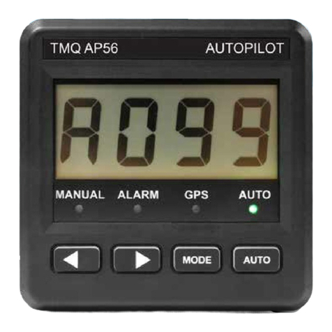
TMQ AP4 Specification sheet

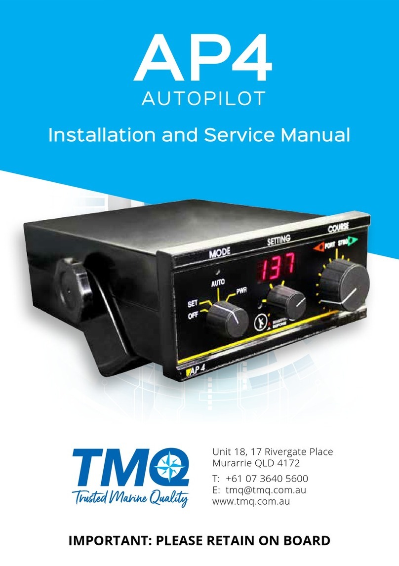
TMQ – AP4
(AP4S10 Rev 4.96)
OPERATION AND INSTALLATION MANUAL
www.tmq.com.au

TMQ AP4 Autopilot (AP4S10) 2 of 62 Version 4.96 9/10/2017
Introduction ................................................................................................. 4
Warning .................................................................................................... 4
Overview .................................................................................................... 4
Autopilot Operation - Standard ................................................................. 5
Set (Standby) ............................................................................................. 6
Auto ........................................................................................................... 7
Power Steering .......................................................................................... 8
GPS – Waypoint Steering ......................................................................... 8
Watch Timer Mode ................................................................................... 9
Commercial Boat Watch Timer ............................................................. 10
Autopilot Operation - Remote Control .................................................... 11
Hand Remote .......................................................................................... 11
Hand Remote Auto Steer .................................................................... 11
Hand Remote Power Steer .................................................................. 12
Active Remote ......................................................................................... 12
Active Remote Auto Steer .................................................................. 13
Active Remote Power Steer ................................................................ 13
Active Remote GPS – Waypoint Steering .......................................... 13
Steering Lever & Electric Helm Steering .............................................. 14
Jog Switch Steering ................................................................................ 15
Sensitivity & Rudder Adjustments .......................................................... 16
Alarms ......................................................................................................... 18
Installation of Autopilot ............................................................................ 20
List of Components ................................................................................. 21
Installation of Main Control Unit .......................................................... 22
Installing a Compass-Top Sensor .......................................................... 24
Installing a Magnetic Sensor Unit (Fluxgate Compass)....................... 25
Magnetic Sensor Unit & Compass Top Sensor Interchange ................ 26
Installation of Rudder Feedback ........................................................... 27
Precautions .......................................................................................... 27
Mounting ............................................................................................. 28
Selection Switch- Standard or Heavy Duty Feedback ........................ 29
Heavy Duty Rudder Feedback Installation Diagram .......................... 30
Standard Rudder Feedback Installation Diagram ............................... 31
Installation of Remote Units .................................................................. 32
Remote Calibration. ............................................................................ 33
NMEA Connection ................................................................................. 33

TMQ AP4 Autopilot (AP4S10) 3 of 62 Version 4.96 9/10/2017
NMEA Socket - Pin Configuration ..................................................... 34
GPS Data Input ................................................................................... 34
Heading Data Connections .................................................................... 35
Heading Data Output .......................................................................... 35
Heading Data Output Selection .......................................................... 36
Heading Data Input ............................................................................. 36
External Alarm Installation ................................................................... 37
Wiring Connections – AP4 Rear Panel ................................................. 38
Examples - Drive Connection Diagrams ............................................... 40
General Information - Drive Units ........................................................ 41
Commissioning Checks ............................................................................. 42
Post Installation Checks ......................................................................... 42
Pre Sailing Dockside Tests ..................................................................... 43
Sea Trials ................................................................................................ 44
Rudder Limits Setting ............................................................................... 45
Compass Calibration ................................................................................. 48
Calibrating TMQ Compass - COMMAG ............................................... 48
Calibrating TMQ Electronic Compass - ELECOM .............................. 49
Resetting Compass to Factory Calibration ............................................ 49
AP4 Special Modes .................................................................................... 50
Operating Without RFU ........................................................................... 52
Adjusting the PID Control ........................................................................ 53
Keeping the Heading .............................................................................. 53
Following a Track (Waypoint) ............................................................... 54
Optional Extras .......................................................................................... 56
Declaration of Conformity ........................................................................ 58
Warranty .................................................................................................... 59
Troubleshooting ......................................................................................... 60

TMQ AP4 Autopilot (AP4S10) 4 of 62 Version 4.96 9/10/2017
Introduction
Warning
AUTOMATIC PILOTS ARE DESIGNED TO BE A NAVIGATIONAL
AID AND SHOULD NEVER BE LEFT SOLELY IN CHARGE OF
THE VESSEL. AN ADEQUATE WATCH SHOULD BE
MAINTAINED AT ALL TIMES.
IT IS RECOMMENDED THAT THE AUTOPILOT NOT BE USED WHILE
NAVIGATING IN RESTRICTED WATERWAYS AS WATER CURRENTS,
WIND CHANGES OR RADIO TRANSMITTER INTERFERENCE MAY
AFFECT VESSEL COURSE SUFFICIENTLY TO ENDANGER YOUR OWN
OR OTHER VESSELS.
Overview
The AP4 autopilot is a rugged & reliable pilot for use on all sorts of vessels,
motor or sail, commercial or pleasure. The front panel has large control knobs
for ease of use in all sea conditions. It has various special modes of operation to
cater for all different requirements.
An AP4 system comprises the following essential components:
Control Unit
Compass
Rudder Feedback Unit
Rudder drive system
Optional Components:
Hand or active remote
Second remote control display
Steering lever or electric helm
Rudder angle indicator
External alarm

TMQ AP4 Autopilot (AP4S10) 5 of 62 Version 4.96 9/10/2017
This autopilot can control the movement of the rudder through a mechanical
drive motor, reversing hydraulic pump, solenoid valves on a constant running
pump or relays. The motor outputs have been carefully designed to work with a
wide range of motors - for more information, consult your dealer or TMQ
Electronics.
The autopilot unit should be installed out of direct sunlight and protected
from water and spray.
The compass must be installed in a place free of magnetic interference,
and connected to the autopilot.
The rudder feedback must be attached to the rudder in such a way that it
can accurately measure the position of the ships rudder and is also
connected to the autopilot.
Provision has been made for two standard remotes, either hand remote or
steering lever. Alternatively one active remote can be used. The special remote
mode of operation may have to be adjusted for the various control devices.
Extra devices may be connected via the internal connection strip, for example,
GPS compass heading input.
For more information on installation of your AP4 autopilot, see the
Installation of Autopilot section of this manual.
For more information on using your AP4 autopilot, see the Autopilot
Operation section of this manual.
All control units operate on 12 or 24 volts DC. Electrical cables are supplied for
interconnection of equipment. Hardware is supplied to mount and couple the
mechanical drive unit into the steering system. Hydraulic installation kits can be
supplied (optional at extra cost) if the pipe size and brand of hydraulic system is
specified.
Autopilot Operation - Standard
The following is a brief overview of the capabilities of the AP4 autopilot. Each
is described in more detail later in following pages.

TMQ AP4 Autopilot (AP4S10) 6 of 62 Version 4.96 9/10/2017
Set/Standby Mode
The digital display shows the current magnetic heading.
The autopilot does not apply any steering corrections.
Auto Mode
The autopilot maintains your boat on the selected magnetic course.
Course can be set or changed by rotating the Course knob or from a
remote steering station.
Power Steer
The rudder may be controlled by the course knob on the main panel or
from a remote steering station.
GPS Mode
When receiving information from a GPS unit, the autopilot can steer a
vessel along a preset track to a precise latitude and longitude.
Watch Timer
A timer can be set from 1 to 120 minutes. When the time expires, an
alarm sounds. Uses include timing of trawling runs or a reminder to
check for anchor drag at set periods.
Commercial Watch Timer
For vessels under survey. The timer can be set to give a warning alarm
at a fixed preset time and provide an output control signal for a loud
external alarm 1 minute after the internal alarm sounds.
Note: External alarm piezo siren must be fitted
Set (Standby)
MODE switch in SET position
The AUTO light is off *
The motor clutch is disengaged *
No steering control output is generated *
The digital display shows the vessels current magnetic course.
Watch Alarm may be set (if required)
Hand remote or steering lever (if installed) is ignored at first turn on.

TMQ AP4 Autopilot (AP4S10) 7 of 62 Version 4.96 9/10/2017
Other special remote modes are accessible (refer later)
* Apart from when in some of the remote modes.
Possible alarm
Watch timer alarm (if set)
Auto
Engaging Auto steering mode
Rotate MODE switch to AUTO
AUTO light is on
Pilot is “locked on” to the course showing on display
Steering control is generated
Rudder can be driven to the limit set position
Waypoint steering can be activated (if GPS available)
Watch alarm can be activated.
Disengaging the Autopilot
Rotate the MODE switch to the SET position
AUTO light is off
Steering control is deactivated.
Display shows boat heading
Boat under manual steering control (helm)
Course Adjustment in AUTO
Rotating the large course control knob (each "click" is 1º course change)
Display shows course to steer after adjustment
Each full rotation of course change knob gives 24º
Possible alarms
Off course (more than 45º)
Watch timer (if set)
FUS Indicated advises the internal fuse is open

TMQ AP4 Autopilot (AP4S10) 8 of 62 Version 4.96 9/10/2017
Power Steering
Engaging Power Steering Mode
Rotate the MODE switch to the PWR position.
AUTO light is on
Display shows boat heading
Boat is steered by rotating the COURSE knob
Change course by rotating knob
Note: The maximum amount of rudder which can be applied is controlled by
Rudder Limit setting (see installation section).
For information on Power Steering with a remote unit (eg: steering levers) see
the section on remote units.
Possible alarm
Watch timer (if set)
FUS Indicated advises the internal fuses is open
GPS – Waypoint Steering
Autopilot must be interfaced to a GPS Plotter generating NMEA 0183 data
output. A route has to be selected on the GPS (refer GPS manual).
Note: Before using this functionality, make sure the auto mode is working
properly and adjusting its variables if necessary. How to adjust the auto
mode is explained in the section “Sensitivity & Rudder Adjustments” and
also. If necessary some advanced settings, they are described in the
sections “AP4 Special Modes” and “Adjusting the PID control”.
Engaging GPS Mode
Switch MODE switch to AUTO
Press GPS button (labelled with a satellite dish)
GPS light will light
Display changes to course to steer (BTW on GPS)
Boat may change course to take up new course (the maximum rate of
turn, if necessary, can be adjusted with the special mode 920)

TMQ AP4 Autopilot (AP4S10) 9 of 62 Version 4.96 9/10/2017
Disengaging GPS Mode
Press the GPS button
GPS light is out
Pilot locks on to current heading of
If no GPS data or AP4 does not receive the data
Autopilot maintains lock on the current course
No GPS data alarm will sound
GPS light will flash
Changing the mode switch to any position other than AUTO will also
disengage the GPS mode.
Setting up your GPS unit
Consult your GPS manual for this procedure first. Because there are a great
variety of GPS units that work with this autopilot, the following is a guide only.
a) GPS must output NMEA 0183 data
b) Data must include at least one of the following sentences:
(i) APA
(ii) APB
(iii) BOD and XTE.
Set up route in GPS
Set arrival zone
Select “auto sequence” if more than one waypoint en route
For XTE output only from GPS steer boat to course before engaging
GPS on pilot.
Remember: Prior to engaging GPS you must program a route into the
GPS for the autopilot to follow
Watch Timer Mode
To set pleasure boat watch timer
Press TIMER button (labelled with a clock)
Display reads time in minutes
Rotate COURSE knob to set time required (max 120 minutes)
Note: After 3 seconds the display reverts to boat heading

TMQ AP4 Autopilot (AP4S10) 10 of 62 Version 4.96 9/10/2017
To reset timer when alarm sounds
When set time expires an alarm will sound
Press TIMER button
Time is reset to original time
Note: If an external alarm is fitted, this will sound 1 minute after the internal
alarm if the timer has not been reset or muted.
To disable (mute) watch timer
Press TIMER button
Rotate COURSE knob until display reads 000
Press TIMER button again
Commercial Boat Watch Timer
Used where survey regulations for commercial vessels require a watch timer
(which includes an external alarm) fitted with an autopilot.
Note:
Once the commercial watch alarm has been enabled, it cannot be
disabled by the user.
To enable the commercial watch timer alarm
Switch AP4 to SET mode.
Hold down the GPS button and press TIMER button
Display shows [900]
Rotate COURSE knob until display reads [906]
Press the TIMER button again
Display shows [A-0]
Rotate COURSE knob until display reads [A-1]
Press the TIMER button
Display shows [A00]
Dial up Commercial Regulation Time, eg: for QLD dial [A05]
Press TIMER button again
Display then reverts to normal heading.

TMQ AP4 Autopilot (AP4S10) 11 of 62 Version 4.96 9/10/2017
Alarm will sound after set time has expired
Press TIMER to reset
When the commercial timer is enabled and the autopilot is in control of the boat
(i.e.: in AUTO, GPS or REMOTE AUTO mode), the AP4 internal alarm
sounds after completion of the selected interval and the louder external alarm
one minute later, unless the timer is previously reset.
In SET, PWR and remote POWER modes, the timer can be set to any required
time as for a pleasure boat.
Autopilot Operation - Remote Control
The following is a brief overview of the capabilities of the AP4 autopilot with
remote control units. Each is described in more detail later in the manual. The
RFU control mode must be selected in order to use the remotes, apart from the
front panel knob and the jog levers.
Hand Remote
Hand Remote Auto Steer
The AP4 can be controlled with a hand remote unit. Auto and power steer
modes can be selected. Special remote response mode r-1 must be set in AP4.
To engage auto steer mode with Hand Remote Unit
Switch AP4 MODE to SET, AUTO or PWR
Set remote knob to centre position
Switch remote switch to AUTO
Pilot locks on to boat heading as for normal autopilot
Change course by +/- 90 º by rotating knob
Note: If remote switch is already in the AUTO position, move switch to OFF
and then back to AUTO.

TMQ AP4 Autopilot (AP4S10) 12 of 62 Version 4.96 9/10/2017
To disengage auto steer mode with Remote Unit
Switch remote switch to OFF
Pilot is now in SET mode
Boat is now steered manually
Note: When the autopilot has been "turned off" using a remote unit (eg: hand
remote, etc), the MODE switch may be in the AUTO or PWR position
BUT steering is under manual control (AUTO LED indicator would be
off). To re-engage the autopilot, use the remote unit switch or move the
MODE switch to SET then back to AUTO. Remote auto steering will also
be disengaged by changing the position of the AP4 MODE switch
Hand Remote Power Steer
To engage power steer mode with Hand Remote
Switch AP4 MODE to SET, AUTO or PWR
Set hand remote knob to centre position
Switch remote switch to POWER STEER
Boat is in power steer control
Steer boat by rotating knob
Note: If remote switch is already in the POWER STEER position, move switch
to OFF and then back to POWER STEER
To disengage power steer mode with Remote Unit
Return remote unit course knob to centre
Switch remote switch to OFF
Pilot is now in SET mode
Boat is now steered using helm
The autopilot will return to SET mode.
Active Remote
The AP4 can be controlled with an active remote unit. Auto, Power Steer, GPS
steering can be selected. Response and Rudder settings of AP4 can be adjusted.
Special internal remote mode r-2 must be set.

TMQ AP4 Autopilot (AP4S10) 13 of 62 Version 4.96 9/10/2017
Active Remote Auto Steer
Note: AP4 must be set to r-2 special remote mode
To engage auto steer mode with Active Remote Unit
Switch AP4 MODE to SET, AUTO or PWR
Set remote knob to centre position
Press AUTO on active remote
AUTO LED on AP4 will light
Pilot locks on to boat heading as for normal autopilot
Change course by +/- 90 º by rotating knob
To disengage auto steer mode with Active Remote Unit
Press STANDBY on active remote
Pilot is now in SET mode. AUTO LED is off
Boat is now steered manually (by helm)
Active Remote Power Steer
To engage power steer mode with Active Remote Unit
Switch AP4 MODE to SET, AUTO or PWR
Set remote knob to centre position
Press POWER STEER on active remote
AUTO LED on AP4 will light
AP4 display shows boat heading
Boat can be steered by rotating active remote knob
To disengage auto steer mode with Active Remote Unit
Press STANDBY on active remote
Pilot is now in SET mode. AUTO LED is off
Boat is now steered manually (by helm)
Active Remote GPS – Waypoint Steering
To Engage GPS Mode
Switch AP4 MODE switch to SET or AUTO
Press GPS button on active remote
GPS light on AP4 will light

TMQ AP4 Autopilot (AP4S10) 14 of 62 Version 4.96 9/10/2017
AP4 display changes to course to steer (BTW on GPS)
Boat may change course to take up new course (maximum rate of turn
is 10º per second)
To Disengage GPS Mode
Press AUTO button on active remote
GPS light on AP4 light is out
Pilot locks on to current heading of boat and is in AUTO mode
Note: Active remote GPS control can also be deactivated by pressing
STANDBY or POWER.
For STANDBY the AP4 reverts to SET mode and the boat is steered
manually (by helm).
For POWER STEER the boat can be steered manually by rotating the
active remote knob.
Steering Lever & Electric Helm Steering
Note: AP4 must be set for the correct special remote mode (see page 32)
The boat may be steered using a steering lever with the AP4. Special internal
remote modes r-3, r-4, r-5 or r-6 must be set in AP4 depending on remote
control connection.
Steering Levers and Electric Helms provide full follow up steering. A steering
lever or electric helm operates in a similar way to a hand remote control.
However, the method of operation will depend on the special remote mode set.
To Engage Steering Lever or Electric Helm
Press select switch (or toggle select switch)
Steer boat using lever or wheel
Note: Some internal remote mode settings allow for power steering at turn on.
To disengage Steering Lever or Electric Helm
Press select switch (or select new MODE on AP4)
Steer boat manually

TMQ AP4 Autopilot (AP4S10) 15 of 62 Version 4.96 9/10/2017
Jog Switch Steering
The boat may be steered using a jog switch input with push button select
switch. Special remote response mode r-7 or r-8 must be set depending on
remote control requirements.
A jog lever is a device comprising a lever under spring tension for centre
reference and two switches for bi directional control.
With AP4 set for JOG input, a number of operations have been included in the
software to extend the use of the AP4 control for some navigational situations
(refer to selection of special remote mode 908, r-7 or r-8 in the subsection
“Special Modes Display Selection” of “AP4 Special Modes”)
When special remote mode r-7 is set and the system is fitted with a jog lever
and separate push button select switch, the boat can be steered using the jog
lever either in AUTO JOG mode or POWER STEER JOG mode.
Jog Switch Wiring
Jog Switch Steering with AP4 in SET
Switch AP4 MODE switch to SET
Press jog lever select button
Boat is now in AUTO JOG under autopilot control
Change course by using jog lever – each jog switch movement gives 1º
course change and a “beep” will sound
For more rapid course change hold jog switch on – course will change
in 2º increments
For POWER JOG press the selection switch

TMQ AP4 Autopilot (AP4S10) 16 of 62 Version 4.96 9/10/2017
Boat is now “manually” steered using the jog switch
To return to AUTO jog press the selection switch again
To toggle between AUTO JOG and POWER JOG press the selection
switch.
To exit JOG control switch the AP4 to OFF/AUTO/PWR
Jog Switch Steering with AP4 in AUTO
Switch AP4 to AUTO – at initial switch on the system will operate in
normal autopilot control; the jog lever will have no effect at this stage
For POWER STEER JOG press jog lever select button
Control rudder movement and direction by jog lever
Manually steer the boat using the jog lever
COURSE knob has no effect in this mode
For AUTO JOG press jog lever select button
Boat is now under autopilot control
Change course by using jog lever – each jog switch movement gives 1º
course change and a “beep” will sound
For more rapid course change hold jog switch on – course will change
in 2º increments
Each successive press of the selection switch will toggle AP4 between
POWER JOG steering and AUTO JOG steering
To return to normal autopilot operation, switch the AP4 to SET then
back to AUTO.
Sensitivity & Rudder Adjustments
The AP4 autopilot has adjustments for setting heading sensitivity and rudder
response to customise the boat for optimum steering performance.
The control in the centre of the AP4 front panel adjusts both sensitivity and
rudder ratio. The centre position is usually suitable for most vessels, but
should the vessel's steering be sensitive or slow, adjustment maybe required.
In general, a vessel with fast turning rate will require a small rudder response
setting. A large, slow vessel may require a higher value for the rudder response.
This may also be adjusted according to speed - low speeds may require more
rudder angle for steering than high speeds.

TMQ AP4 Autopilot (AP4S10) 17 of 62 Version 4.96 9/10/2017
Sensitivity
This adjusts the rudder sensitivity (sometimes known as dead band) which
varies the tolerance to the position of the rudder from the control in auto
mode. This setting relates directly to the dead band of the vessel’s
direction, in other words, how much “wander” is allowed before the
autopilot reacts to correct any change.
Increasing the value of this setting, will increase the tolerance to the
rudder position error. Decreasing it will make the rudder position and the
vessel’s route more accurate, but decreasing to much may make the vessel
oscillates to much around its direction.
Rudder Ratio
This control adjusts the rudder ratio which varies the amount of rudder
applied for a course error.
To adjust sensitivity
If Display is reading Heading 000-365 pull out centre knob
Display will read a number eg: 05
Adjust the knob anticlockwise until pilot just begins to hunt (this is
indicated by the port and starboard lights flickering)
Turn knob clockwise until lights are not flickering.
Push knob to set and back to compass display.
To adjust rudder ratio
Display is reading Heading 000-365
Rotate centre knob
Display will read a number eg: 06
Adjust knob until boat steers a straight course. Note the reading.
Display will return to Heading
If Display is indicating Rudder Angle Push button to Heading display.
Note: The sensitivity and rudder are normally adjusted together with sensitivity
being adjusted first, then rudder ratio.
The sensitivity should be adjusted so that the AP4 is not continually driving
back and forth (hunting) as this can prematurely wear your steering system
If the centre knob is left out after the sensitivity is set, when 3 seconds has
elapsed, the AP4 display will read rudder angle.

TMQ AP4 Autopilot (AP4S10) 18 of 62 Version 4.96 9/10/2017
When the rudder ratio setting is too low, turns will take an excessive amount
of time, and the vessel may "wander".
When the rudder ratio setting is too high, turns will be rapid and the vessel
will oversteer.
Experiment will find the best settings for your vessel. Only make small
changes at a time.
Alarms
A number of conditions will cause alarms to sound. Each alarm has a different
"beep pattern" (except watch timer and commercial watch alarm). The external
alarm output may also be turned on by some of these alarms; this does not have
a "beep pattern" but instead it sounds continually.
Watch Timer Alarm
This alarm indicates that the time set by the user has expired.
Alarm pattern is 1 second on, 1 second off until reset.
Commercial Watch Alarm (Option)
This alarm indicates that the autopilot is in control of the vessel but timer key
has not been pressed within the last five minutes (if set for 5 minutes). Alarm
pattern is 1 second on then 1 second off until reset.
The external alarm output is turned on 1 minute after the internal alarm begins
to sound.
Angle Off Course Alarm
The alarm pattern is 0.2 seconds on, 0.2 seconds off when vessel is more than
45 degrees from course-to-steer.

TMQ AP4 Autopilot (AP4S10) 19 of 62 Version 4.96 9/10/2017
No GPS Data Alarm (Waypoint Steering)
The alarm sounds 0.5 seconds on, 0.5 seconds off if the autopilot is not
receiving valid information from the GPS.
No Heading Reference (NMEA Heading or GPS Input)
The alarm sounds 0.5 seconds on, 0.5 seconds off if the autopilot is not
receiving heading data or GPS data for heading reference.
Bridge Navigational Watch Alarm System (BNWAS)
This alarm is set to ON or OFF via special display mode 913. When it is ON,
the external alarm terminal will be kept active low while the device is in auto
mode. It is intended for being connected to an external BNWAS controller. In
any other mode, different from auto, the external alarm will be open circuit.
From the factory, this alarm mode is OFF.

TMQ AP4 Autopilot (AP4S10) 20 of 62 Version 4.96 9/10/2017
Installation of Autopilot
EMC Considerations & Precautions:
All TMQ equipment and accessories are designed to the best industry standard
for use in the marine environment. Their design and manufacture conforms to
the appropriate Electromagnetic Compatibility (EMC) standards, but good
installation is required to ensure that performance is not compromised.
Although every effort has been taken to ensure the autopilot will perform under
all conditions, it is important to understand that some factors could affect the
operation of the product.
Installation instructions are provided in this manual. Some preliminary
suggestions follow:
Installation:
To reduce the risk of operating problems, all TMQ equipment and cables
connected to it should be at least 1 metre (3 feet) from any equipment
transmitting or cables carrying radio signals, eg: VHF radios, cables and
antennas. In the case of SSB radios, the distance should be increased to 2
metres (7 feet).
Position of electronic compass is important to ensure no magnetic interference.
It may be necessary to trial several positions before deciding on an optimum
position. Check other side of bulkhead, dash and/or deckhead for any material
which may interfere with the compass (steel or iron in particular). Keep
electronic compass away from the boat’s magnetic compass.
Check:
Always check the installation before going to sea to make sure that it is not
affected by radio transmissions, engine starting, low battery voltage or other
problems.
In some installations it may not be possible to prevent the equipment from
being affected by external influences. Usually this will not damage the
equipment but may cause momentary incorrect operation.
Other manuals for AP4
2
Table of contents
Other TMQ Autopilot System manuals
Popular Autopilot System manuals by other brands
Garmin
Garmin GHP 20 Marine Autopilot System for... installation instructions
Raymarine
Raymarine SmartPilot S1000 user guide
Raymarine
Raymarine RayPilot 650 user guide
Shark
Shark X8 user manual
Dynon Avionics
Dynon Avionics SkyView HDX installation manual

Raymarine
Raymarine Verado Installation and commissioning
