TNA TX7240 User manual

TX7240
Loop Relay Module
Installation and Operation Manual
TANDA UK Technology Copyright ©2016, All right reserved.

TX7240 Loop Relay Module
Installation & Operation Manual
4050100366-Rev1.0-1116
TANDA UK
Specifications are subject to change without prior notice
2
Product Safety
To prevent severe injury and loss of life or property, read the instruction carefully before installing the
module to ensure proper and safe operation of the system.
European Union directive
2012/19/EU (WEEE directive): Products marked with this symbol cannot be disposed
of as unsorted municipal waste in the European Union. For proper recycling, return
this product to your local supplier upon the purchase of equivalent new
equipment, or dispose of it at designated collection points.
For more information please visit the website at www.recyclethis.info

TX7240 Loop Relay Module
Installation & Operation Manual
4050100366-Rev1.0-1116
TANDA UK
Specifications are subject to change without prior notice
3
Table of Content
1 Introduction ............................................................................................................................................ 4
1.1 Overview .......................................................................................................................................... 4
1.2 Feature and Benefits...................................................................................................................... 4
1.3 Technical Specification................................................................................................................. 4
2 Installation............................................................................................................................................... 5
2.1 Installation Preparation ................................................................................................................. 5
2.2 Installation and Wiring ................................................................................................................... 5
3 Loop relay module Configuration ..................................................................................................... 5
3.1structure characteristics and Working principle....................................................................... 5
3.1.1 Outline dimension chart ............................................................................................................ 5
3.1.2Working principle......................................................................................................................... 6
3.2 Use and Operation......................................................................................................................... 6
3.3 Handling and storage ....................................................................................................................... 6
4 General Maintenance ......................................................................................................................... 6
5 Matters needing attention ................................................................................................................. 7
Appendix 1................................................................................................................................................. 7
Limitation of loop relay module......................................................................................................... 7

TX7240 Loop Relay Module
Installation & Operation Manual
4050100366-Rev1.0-1116
TANDA UK
Specifications are subject to change without prior notice
4
1 Introduction
1.1 Overview
TX7240 loop relay module uses DC24V power supply, through the internal electrical isolation circuit,
realize the input bus signal and the output bus signal isolated real-time transmission, output standard
bus waveform. The loop relay module can improve the anti-interference ability of the bus, and has
the function of extending the communication distance of the bus. The bus signal is mainly used in
the field of external interference distortion or need to extend the communication distance of the bus.
The unit manufactured base on the requirement of EN 54 part 18, European Standard. The unit is
aesthetically pleasing with unobtrusive design that will complement modern building designs and its
plug-in type assembles make installation and maintenance more convenient to the installer. The unit
is compatible to the TX7004 Analogue Intelligent Fire Alarm Control Panel, produced by single
manufacture T&A, to avoid addressable communication compatibility problem.
1.2 Feature and Benefits
EN54-18 Compliance
Built-in MCU processor
Input bus, the output bus signal between the electrical isolation, electromagnetic
interference has a good inhibitory capacity, stable and reliable work Input Fire or Supervisory
signal configuration
LED status indicator
To correct the bus signal, the output standard bus waveform
Fast intelligent bus output short circuit judge function, bus output short circuit protection
function; after the bus is normal, it can recover the bus output in time
Aesthetically pleasing design
1.3 Technical Specification
Compliance EN 54-18:2005
Input Voltage Loop Power:24VDC [16V to 28V]
External PSU: 20 to 28VDC
Current Consumption Loop: ≤5mA
External PSU: ≤500mA
Bus input range: ≤1000m Bus output range: ≤1000m
Most cascade three
Protocol/Addressing T&A, Value range from 1 to 254
Indicator Status Normal: Single blink/Fault: Steady-on
Material / Colour metal / gray
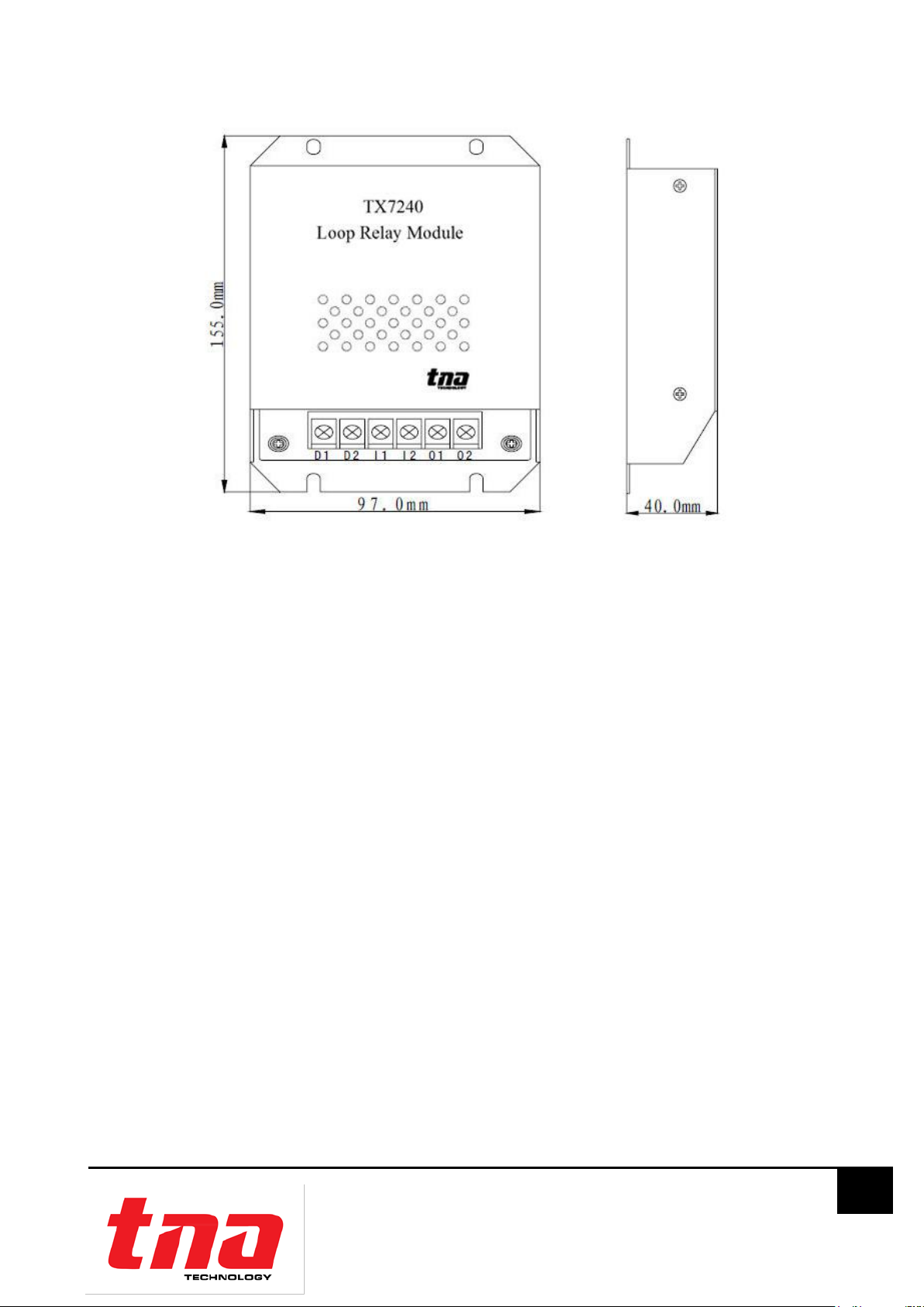
Dimension / LWH 155.0mm×97.0mm×40.0mm
Operating Temperature -10°C to +55°C
Humidity 0 to 95% Relative Humidity, Non condensing
TX7240 Loop Relay Module
Installation & Operation Manual
4050100366-Rev1.0-1116
TANDA UK
Specifications are subject to change without prior notice
5
2 Installation
2.1 Installation Preparation
This interface module must be installed, commissioned and maintained by a qualified or factory
trained service personnel. The installation must be installed in compliance with all local codes having
a jurisdiction in your area or BS 5839 Part 1 and EN54.
T&A products has available range of interfaces, each interface module is designed for specific
application, it is essential to consider the requirement of both sides of the interface to avoid
malfunction and typical fault scenario. The main caution is to ensure that the voltage rating of the
equipment and interface module are compatible.
2.2 Installation and Wiring
1. The loop relay module is used for anti interference when used outside the site should be
installed in the presence of disturbances, such as the shielding effect of the iron shell; relay
module as extended bus communication distance is used, should be installed at the output
end of long distance bus controller within 1000m; fixed by screws, installed in the room.
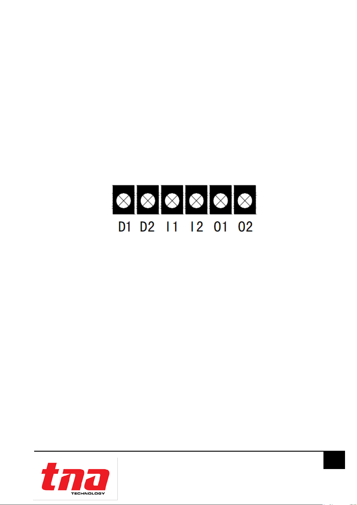
2. External wiring terminal diagram is shown below:
D1、D2: 24V power input terminal
I1、I2: Bus input terminal
O1、O2: Bus output terminal, O1 is the positive, O2 is the negative.
Wiring requirements: no polarity signal two bus using RVS twisted pair, Sectional area≥1.0mm²;
DC24V power using BV line, Sectional area≥1.5mm²
NOTE: the TX7240 cannot be used in the loop.
3 Loop relay module Configuration
3.1structure characteristics and Working principle
3.1.1 Outline dimension chart
Loop relay module Outline dimension chart, As shown in Figure 2:
Figure 1: Schematic diagram of external terminals
TX7240 Loop Relay Module
Installation & Operation Manual
4050100366-Rev1.0-1116
TANDA UK
Specifications are subject to change without prior notice
6
3.1.2Working principle
The loop relay module collects the bus signal through the bus transceiver circuit, and outputs the
control bus output circuit after the MCU processing the standard bus waveform; signal isolation
circuit bus input and output through optocoupler can extend bus communication distance and can
correct the bus waveform
3.2 Use and Operation
1. The use of the loop relay module must follow the following requirements:
(1) Meet the technical parameters defined in this specification
2. After the loop relay module is installed, or in the use of the process to be tested every six
months, the test method is as follows:
(1) The fire alarm controller is used to connect the front end coding device with the relay
module, and the coding equipment should be able to log in correctly.
(2) The detector which is connected to the bus through the relay module is reported to the
fire alarm, and the controller should be able to receive the alarm information correctly.
3.3 Handling and storage
Transport, storage and handling equipment shall be carried out in a packing condition, loading and
unloading process must be handled with care, to prevent the collision damage. Storage Keep the
environment should keep ventilation, dry, avoid open storage.
4 General Maintenance
1. Inform the suitable personnel before conducting the maintenance.
2. Disable the loop relay module on the control panel to prevent false alarm.
3. Do not attempt to repair the circuitry of the loop relay module, it may affect the operation to
respond to a fire condition and will void the manufacturer’s warranty.
4. Notify again proper personnel after conducting the maintenance and make sure to enable
the loop relay module and confirm if up and running.
5. Perform the maintenance on semi-annually or depending on the site conditions.
Figure 2: Loop relay module figure size

TX7240 Loop Relay Module
Installation & Operation Manual
4050100366-Rev1.0-1116
TANDA UK
Specifications are subject to change without prior notice
7
5 Matters needing attention
1. On duty personnel should be familiar with the operation of the equipment, not the wrong
operation.
2. This module for fire protection products, must strictly implement the duty system and the shift
in use, and make a running record.
3. Not every half a year to be a function of the module test.
Appendix 1
Limitation of loop relay module
The loop relay module cannot last forever. In order to keep the loop relay module working in good
condition, please maintain the equipment continuously according to recommendations from
manufacturers and relative nation codes and laws. Take specific maintenance measures on the
basis of different environments.
These loop relay module contains electronic parts. Even though it is made to last for a long period of
time, any of these parts could fail at any time. Therefore, test your module at least every half-year
according to national codes or laws. Any loop relay module, fire alarm devices or any other
components of the system must be repaired and/or replaced immediately as they fail.
Table of contents


