manuals.online logo
Brands
  1. Home
  2. •
  3. Brands
  4. •
  5. Toshiba
  6. •
  7. Relay
  8. •
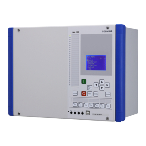
  9. Toshiba GRD130-210 User manual

Toshiba GRD130-210 User manual

6F2S0757
INSTRUCTION MANUAL
UNDER/OVERVOLTAGE PROTECTION RELAY
GRD130
©TOSHIBA Corporation 2003
All Rights Reserved.
( Ver. 2.4 )
1
6F2S0757
Safety Precautions
Before using this product, please read this chapter carefully.
This chapter describes the safety precautions recommended when using the GRD130. Before
installing and using the equipment, this chapter must be thoroughly read and understood.
Explanation of symbols used
Signal words such as DANGER, WARNING, and two kinds of CAUTION, will be followed by
important safety information that must be carefully reviewed.
Indicates an imminently hazardous situation which will result in death or
serious injury if you do not follow the instructions.
Indicates a potentially hazardous situation which could result in death or
serious injury if you do not follow the instructions.
CAUTION Indicates a potentially hazardous situation which if not avoided, may result in
minor injury or moderate injury.
CAUTION Indicates a potentially hazardous situation which if not avoided, may result in
property damage.
DANGE
R
WARNING
2
6F2S0757
•Exposed terminals
Do not touch the terminals of this equipment while the power is on, as the high voltage generated
is dangerous.
•Residual voltage
Hazardous voltage can be present in the DC circuit just after switching off the DC power supply.
It takes approximately 30 seconds for the voltage to discharge.
•Fiber optic
Do not view directly with optical instruments.
CAUTION
•Earth
The earthing terminal of the equipment must be securely earthed.
CAUTION
•Operating environment
The equipment must only used within the range of ambient temperature, humidity and dust
detailed in the specification and in an environment free of abnormal vibration.
•Ratings
Before applying AC voltage or the DC power supply to the equipment, check that they conform
to the equipment ratings.
•Printed circuit board
Do not attach and remove printed circuit boards when the DC power to the equipment is on, as
this may cause the equipment to malfunction.
•External circuit
When connecting the output contacts of the equipment to an external circuit, carefully check the
supply voltage used in order to prevent the connected circuit from overheating.
•Connection cable
Carefully handle the connection cable without applying excessive force.
•DC power
If dc power has not been supplied to the relay for two days or more, then all fault records, event
records and disturbance records and internal clockmay be cleared soon after restoring the power.
This is because the back-up RAM may have discharged and may contain uncertain data.
•Modification
Do not modify this equipment, as this may cause the equipment to malfunction.
•Short-link
Do not remove a short-link which is mounted at the terminal block on the rear of the relay before
shipment, as this maycause the performance of this equipment such as withstand voltage, etc., to
reduce.
•Disposal
When disposing of this equipment, do so in a safe manner according to local regulations.
WARNING
3
6F2S0757
Contents
Safety Precautions 1
1. Introduction 6
2. Application Notes 9
2.1 Phase Overvoltage Protection 9
2.1.1 Inverse Time Overvoltage Protection 9
2.1.2 Definite Time Overvoltage Protection 12
2.1.3 Settings 13
2.2 Phase Undervoltage Protection 14
2.2.1 Inverse Time Undervoltage Protection 14
2.2.2 Definite Time Undervoltage Protection 17
2.2.3 Settings 18
2.3 Zero Phase Sequence Overvoltage Protection 19
2.4 Negative Phase Sequence Overvoltage Protection 23
2.5 Trip Signal Output 26
3. Technical Description 27
3.1 Hardware Description 27
3.1.1 Outline of Hardware Modules 27
3.2 Input and Output Signals 31
3.2.1 AC Input Signals 31
3.2.2 Binary Input Signals 31
3.2.3 Binary Output Signals 34
3.3 Automatic Supervision 35
3.3.1 Basic Concept of Supervision 35
3.3.2 Relay Monitoring 35
3.3.3 Trip Circuit Supervision 36
3.3.4 Circuit Breaker Monitoring 37
3.3.5 Failure Alarms 37
3.3.6 Trip Blocking 38
3.3.7 Setting 38
3.4 Recording Function 39
3.4.1 Fault Recording 39
3.4.2 Event Recording 40
3.4.3 Disturbance Recording 40
3.5 Metering Function 42
4. User Interface 43
4.1 Outline of User Interface 43
4.1.1 Front Panel 43
4.1.2 Communication Ports 45
4.2 Operation of the User Interface 46
4.2.1 LCD and LED Displays 46
4
6F2S0757
4.2.2 Relay Menu 49
4.2.3 Displaying Records 52
4.2.4 Displaying the Status 56
4.2.5 Viewing the Settings 60
4.2.6 Changing the Settings 61
4.2.7 Testing 84
4.3 Personal Computer Interface 87
4.4 Relay Setting and Monitoring System 87
4.5 IEC 60870-5-103 Interface 88
4.6 Clock Function 88
5. Installation 89
5.1 Receipt of Relays 89
5.2 Relay Mounting 89
5.3 Electrostatic Discharge 89
5.4 Handling Precautions 89
5.5 External Connections 90
6. Commissioning and Maintenance 91
6.1 Outline of Commissioning Tests 91
6.2 Cautions 92
6.2.1 Safety Precautions 92
6.2.2 Cautions on Tests 92
6.3 Preparations 93
6.4 Hardware Tests 94
6.4.1 User Interfaces 94
6.4.2 Binary Input Circuit 94
6.4.3 Binary Output Circuit 95
6.4.4 AC Input Circuits 96
6.5 Function Test 98
6.5.1 Measuring Element 98
6.5.2 Protection Scheme 104
6.5.3 Metering and Recording 104
6.6 Conjunctive Tests 105
6.6.1 On Load Test 105
6.6.2 Tripping Circuit Test 105
6.7 Maintenance 107
6.7.1 Regular Testing 107
6.7.2 Failure Tracing and Repair 107
6.7.3 Replacing Failed Relay Unit 108
6.7.4 Resumption of Service 109
6.7.5 Storage 109
7. Putting Relay into Service 110
5
6F2S0757
Appendix A Signal List 111
Appendix B Event Record Items 115
Appendix C Binary Output Default Setting List 119
Appendix D Details of Relay Menu 121
Appendix E Case Outline 133
Appendix F External Connection 135
Appendix G Relay Setting Sheet 143
Appendix H Commissioning Test Record 151
Appendix I Return Repair Form 155
Appendix J Technical Data 161
Appendix K Symbols Used in Scheme Logic 167
Appendix L IEC60870-5-103: Interoperability 171
Appendix M Ordering 179
The data given in this manual are subject to change without notice. (Ver.2.4)
6
6F2S0757
1. Introduction
GRD130 series relays provide overvoltage and undervoltage protection for distribution
substations, generators, motors and transformers.
The GRD130 series has two models and provides the following protection schemes in both
models.
•Overvoltage and undervoltage protection with definite time or inverse time characteristics
•Instantaneous overvoltage and undervoltage protection
The GRD130 series provides the following protection schemes depending on the models.
•Zero phase sequence overvoltage protection
•Negative phase sequence overvoltage protection
The GRD130 series provides the following functions for all models.
•Four settings groups
•Configurable binary inputs and outputs
•Circuit breaker condition monitoring
•Trip circuit supervision
•Automatic self-supervision
•Menu-based HMI system
•Configurable LED indication
•Metering and recording functions
•Communications for remote setting and data download is provided by the RSM (Relay
Setting and Monitoring) system.
•Front mounted RS232 serial port for local PC communications
•Rear mounted RS485 serial port for remote PC communications
•IEC60870-5-103 protocol is provided for communication with substation control and
automation systems.
Table 1.1.1 shows the members of the GRD130 series and identifies the functions to be provided
by each member.
7
6F2S0757
Table 1.1.1 Series Members and Functions
: Scheme switch [APPL] setting
GRD130 -
210 410
Model Number
1PP 1PN 2PP 3PN 3PV 3PP 2PP
Voltage input 1PP + V01PN + V02PP 3PN 3PN + V03PP + V02PP + V0
IDMT O/V 9999999
DT O/V 9999999
IDMT U/V 9999999
DT U/V 9999999
ZPS IDMT O/V 999(∗) 999
ZPS DT O/V 999(∗) 999
NPS IDMT O/V 99999
NPS DT O/V 99999
Trip circuit
supervision 9999999
Self supervision 9999999
CB state monitoring 9999999
Trip counter alarm 9999999
Multiple settings
groups 9999999
Metering 9999999
Fault records 9999999
Event records 9999999
Disturbance records 9999999
Communication 9999999
1PP: single phase-to-phase voltage
1PN: single phase-to-neutral voltage
2PP: two phase-to-phase voltage
3PP: three phase-to-phase voltage
3PN: three phase-to-neutral voltage
V0: residual voltage (VE)
IDMT: inverse definite minimum time
DT: definite time
O/V: overvoltage protection
U/V: undervoltage protection
ZPS: zero phase sequence
NPS: negative phase sequence
(∗): V0calculated from three phase voltages.
CAUTION:
Do not change the APPL setting under service condition of the relay.
8
6F2S0757
Model 210 provides single-phase overvoltage and undervoltage protection with zero sequence
overvoltage protection or two-phase overvoltage and undervoltage with negative sequence
overvoltage protection, depending on the scheme switch [APPL] setting.
Model 410 provides three-phase or two-phase overvoltage and undervoltage protection with zero
sequence overvoltage protection and negative sequenceovervoltage protection, depending on the
scheme switch [APPL] setting.
9
6F2S0757
2. Application Notes
2.1 Phase Overvoltage Protection
GRD130 provides three independent phase overvoltage elements. OV1 and OV2 are
programmable for inverse time (IDMT) or definite time (DT) operation. OV3 has definite time
characteristic only.
2.1.1 Inverse Time Overvoltage Protection
The inverse time overvoltage protection element OV1 and OV2 have the IDMT characteristic
defined by equation (1):
()










+










−
×= c
Vs
V
k
TMSt a1
(1)
where:
t = operating time for constant voltage V (seconds),
V = energising voltage (V),
Vs = overvoltage setting (V),
TMS = time multiplier setting
k, α, c = constants defining curve.
The standard IDMT characteristic [IDMT] of GRD130 is illustrated in Figure 2.1.1.
In addition to the standard IDMT curve, the OV1 and OV2 can provide user configurable IDMT
curve. If required, set the scheme switch [OV∗EN] to “C” and set the curve defining constants k,
α, and c. The following table shows the setting ranges of the curve defining constants.
Table 2.1.1 Specification of IDMT Curves
Curve Description Curve Defining Constants
k
αc
Standard “IDMT” 1 1 0
User configurable curve 0.00 – 300.00 0.00 – 5.00 0.000 – 5.000
Definite time reset
A definite time resetting characteristic is applied to the OV1 and OV2 elements when the inverse
time delay is used.
If definite time resetting is selected, and the delay period is set to instantaneous, then no
intentional delay is added. As soon as the energising voltage falls below the reset threshold, the
element returns to its reset condition.
If the delay period is set to some value in seconds, then an intentional delay is added to the reset
period. If the energising voltage exceeds the setting for a transient period without causing
tripping, then resetting is delayed for a user-definable period. When the energising voltage falls
below the reset threshold, the integral state (the point towards operation that it has travelled) of
the timing function (IDMT) is held for that period.
10 
6F2S0757
This does not apply following a trip operation, in which case resetting is always instantaneous.
The OV1 and OV2 have a programmable dropoff/pickup(DO/PU) ratio.
Overvoltage Inverse Time Curves
0.100
1.000
10.000
100.000
1000.000
11.522.53
Applied Voltage (x Vs)
Operating Time (secs)
TMS = 1
TMS = 2
TMS = 5
TMS = 10
Figure 2.1.1 IDMT Characteristic for OV
Scheme Logic
Figure 2.1.2 shows the scheme logic of the overvoltage protection with selective definite time or
inverse time characteristic.
The definite time protection is selected by setting [OV1EN] to “DT”. Definite time operation is
enabled for overvoltage protection, and trip signal OV1 TRIP is given through the delayed
pick-up timer TOV1.
The inverse time protection is selected by setting [OV1EN] to “IDMT” or “C”. Inverse time
operation is enabled for overvoltage protection, and trip signal OV1 TRIP is given.
These protections can be disabled by the scheme switch [OV1EN] or binary input signal OV1
BLOCK.
OV2 provides the same logic as the OV1.
11 
6F2S0757
(∗)Note : Phases 1, 2 and 3 are replaced with the followings:
[APPL] setting
Phase 1PP 1PN 2PP 3PN, 3PV 3PP
1 phase-to-phase phase-to-neutral A - B phase A phase A - B phase
2 --B - C phase B phase B - C phase
3 ---C phase C - A phase
Figure 2.1.2 Overvoltage Protection (OV1, OV2)
≥1
≥1
≥1
OV1 TRIP
≥
1
0.00 - 300.00s
TOV1
t0
t0
t0
&
&
&
&
&
&
1(∗)
OV1 2(∗)
3(∗)
OV1-3(∗) TRIP
OV1-1(∗) TRIP
OV1-2(∗) TRIP
&
&
&
1
OV1 BLOCK
"DT"
"IDMT" or “C”
[OV1EN]
+
≥1
≥1
≥1
≥1
OV2 TRIP
≥
1
0.00 - 300.00s
TOV2
t0
t0
t0
&
&
&
&
&
&
1(∗)
OV2 2(∗)
3(∗) &
&
&
1
OV2 BLOCK
"DT"
"IDMT" or “C”
[OV2EN]
+
≥1
OV2-3(∗) TRIP
OV2-1(∗) TRIP
OV2-2(∗) TRIP
12 
6F2S0757
2.1.2 Definite Time Overvoltage Protection
OV3 element is used for definite time overvoltage protection.
The OV3 element has a programmable DO/PU ratio.
Scheme Logic
Figure 2.1.3 shows OV3 scheme logic. The OV3 gives a signal through delayed pick-up timer
TOV3. The OV3 is mainly used to output alarm signal OV3 ALARM. The alarm can be blocked
by incorporated scheme switch [OV3EN] and binary input signal OV3 BLOCK.
(∗)Note : Phases 1, 2 and 3 are replaced with the followings:
[APPL] setting
Phase 1PP 1PN 2PP 3PN, 3PV 3PP
1 phase-to-phase phase-to-neutral A - B phase A phase A - B phase
2 --B - C phase B phase B - C phase
3 ---C phase C - A phase
Figure 2.1.3 Definite Time Overvoltage Protection (OV3)
OV3 ALARM
≥
1
OV3 BLOCK 1
+ "On"
[OV3EN]
0.00 - 100.00s
&
&
&
TOV3
1(∗)
OV3 2(∗)
3(∗)
t0
t0
t0
13 
6F2S0757
2.1.3 Settings
The table shows the setting elements necessary for the overvoltage protection and their setting
ranges.
Element Range Step Default Remarks
OV1 10.0 – 200.0 V 0.1 V 120.0 V OV1 threshold setting
0.05 – 100.00 0.01 10.00 OV1 IDMT time multiplier setting.
Required if [OV1EN] = 2 or 3.
TOV1
0.00 – 300.00 s 0.01 s 0.10 s OV1 definite time setting. Required if
[OV1EN] = 1.
TOV1R 0.0 – 300.0 s 0.1 s 0.0 s OV1 definite time delayed reset.
Required if [OV1EN] = 2 or 3.
OV1DPR 10 – 98 % 1 % 95 % OV1 DO/PU ratio setting.
OV2 10.0 – 200.0 V 0.1 V 140.0 V OV2 threshold setting.
0.05 – 100.00 0.01 10.00 OV2 IDMT time multiplier setting.
Required if [OV2EN] = 2 or 3.
TOV2
0.00 – 300.00 s 0.01 s 0.10 s OV2 definite time setting. Required if
[OV2EN] = 1.
TOV2R 0.0 – 300.0 s 0.1 s 0.0 s OV2 definite time delayed reset.
Required if [OV2EN] = 2 or 3.
OV2DPR 10 - 98 % 1 % 95 % OV2 DO/PU ratio setting.
OV3 10.0 – 200.0 V 0.1 V 160.0 V OV3 threshold setting.
TOV3 0.00 – 300.00 s 0.01 s 0.10 s OV3 definite time setting.
OV3DPR 10 - 98 % 1 % 95 % OV3 DO/PU ratio setting.
[OV1EN] Off / DT / IDMT / C Off OV1 Enable
[OV2EN] Off / DT / IDMT / C Off OV2 Enable
[OV3EN] Off / On Off OV3 Enable
14 
6F2S0757
2.2 Phase Undervoltage Protection
GRD130 provides three independent phase undervoltage elements. UV1 and UV2 programmable
for inverse time (IDMT) or definite time (DT) operation. UV3 has definite time characteristic
only.
2.2.1 Inverse Time Undervoltage Protection
The inverse time undervoltage protection element UV1 and UV2 have the IDMT characteristic
defined by equation (2):
()










+










−
×= c
Vs
V
k
TMSt a
1
(2)
where:
t = operating time for constant voltage V (seconds),
V = energising voltage (V),
Vs = undervoltage setting (V),
TMS = time multiplier setting,
k, α, c = constants defining curve.
The standard IDMT characteristic of GRD130 is illustrated in Figure 2.2.1.
In addition to the standard IDMT curve, the UV1 and UV2 can provide user configurable IDMT
curve. If required, set the scheme switch [UV∗EN] to “C” and set the curve defining constants k,
α, and c. The following table shows the setting ranges of the curve defining constants.
Table 2.2.1 Specification of IDMT Curves
Curve Description Curve Defining Constants
k
αc
Standard “IDMT” 1 1 0
User configurable curve 0.00 – 300.00 0.00 – 5.00 0.000 – 5.000
Definite time reset
The definite time resetting char-acteristic is applied to the UV1 and UV2 elements when the
inverse time delay is used.
If definite time resetting is selected, and the delay period is set to instantaneous, then no
intentional delay is added. As soon as the energising voltage rises above the reset threshold, the
element returns to its reset condition.
If the delay period is set to some value in seconds, then an intentional delay is added to the reset
period. If the energising voltage is below the undercurrent setting for a transient period without
causing tripping, then resetting is delayed for a user-definable period. When the energising
voltage rises above the reset threshold, the integral state (the point towards operation that it has
travelled) of the timing function (IDMT) is held for that period.
This does not apply following a trip operation, in which case resetting is always instantaneous.
15 
6F2S0757
Undervoltage Inverse Time Curves
1.000
10.000
100.000
1000.000
0 0.2 0.4 0.6 0.8 1
Applied Voltage (x Vs)
Operating Time (secs)
TMS = 10
TMS = 5
TMS = 2
TMS = 1
Figure 2.2.1 IDMT Characteristic for UV
Scheme Logic
Figure 2.2.2 shows the scheme logic of the undervoltage protection with selective definite time
or inverse time characteristic.
The definite time protection is selected by setting [UV1EN] to “DT”. Definite time operation is
enabled for undervoltage protection, and trip signal UV1 TRIP is given through the delayed
pick-up timer TUV1.
The inverse time protection is selected by setting [UV1EN] to “IDMT” or “C”. Inverse time
operation is enabled for undervoltage protection, and trip signal UV1 TRIP is given.
These protections can be disabled by the scheme switch [UV1EN] or binary input signal UV1
BLOCK.
In addition, when applying to detect the moderate voltage drop by load shedding, there is a user
programmable voltage threshold VBLK. If all measured phase voltages drop below this setting,
then the undervoltage protection is prevented from operating. This function can be disabled by
the scheme switch [VBLKEN]. The [VBLKEN] should be set to “OFF” (no use) when the UV
elements are used as fault detectors, and set to “ON” (use) when used for load shedding.
Note: When [VBLKEN] is “On”, the VBLK must be set lower than any other UV setting values and
the UV should be set to a time delayed tripping.
UV2 provides the same logic as the UV1.
16 
6F2S0757
(∗)Note : Phases 1, 2 and 3 are replaced with the followings:
[APPL] setting
Phase 1PP 1PN 2PP 3PN, 3PV 3PP
1 phase-to-phase phase-to-neutral A - B phase A phase A - B phase
2 --B - C phase B phase B - C phase
3 ---C phase C - A phase
Figure 2.2.2 Undervoltage Protection (UV1, UV2)
≥1
≥1
≥1
UV1 TRIP
≥
1
0.00 - 300.00s
TUV1
t0
t0
t0
&
&
&
&
&
&
1(∗)
UV1 2(∗)
3(∗)
UV1-3(∗) TRIP
UV1-1(∗) TRIP
UV1-2(∗) TRIP
&
&
&
1
UV1 BLOCK
"DT"
"IDMT" or “C”
[UV1EN]
+
≥1
1 NON
UVBLK
&
"ON"
[VBLKEN]
+
"OFF"
[UVTST]
+
UVBLK
≥1
≥1
≥1
UV2 TRIP
≥
1
0.00 - 300.00s
TUV2
t0
t0
t0
&
&
&
&
&
&
1(∗)
UV2 2(∗)
3(∗)
UV2-3(∗) TRIP
UV2-1(∗) TRIP
UV2-2(∗) TRIP
&
&
&
1
UV2 BLOCK
"DT"
"IDMT" or “C”
[UV2EN]
+
≥1
17 
6F2S0757
2.2.2 Definite Time Undervoltage Protection
UV3 element is used for definite time undervoltage protection.
Scheme Logic
As shown in Figure 2.2.3, UV3 has independent scheme logic. The UV3 gives a signal through
delayed pick-up timer TUV3. The UV3 is mainlyused to output alarm signal UV3 ALARM. The
alarm can be blocked by incorporated scheme switch [UV3EN] and binary input signal UV3
BLOCK.
(∗)Note : Phases 1, 2 and 3 are replaced with the followings:
[APPL] setting
Phase 1PP 1PN 2PP 3PN, 3PV 3PP
1 phase-to-phase phase-to-neutral A - B phase A phase A - B phase
2 --B - C phase B phase B - C phase
3 ---C phase C - A phase
Figure 2.2.3 Definite Time Undervoltage Protection (UV3)
UV3 ALRAM
≥
1
0.00 - 100.00s
&
&
TUV3
t0
t0
t0
"On"
[UV3EN]
+
&
&
&
&
UV3 BLOCK 1
NON BLK
1(∗)
UV3 2(∗)
3(∗)
18 
6F2S0757
2.2.3 Settings
The table shows the setting elements necessary for the undervoltage protection and their setting
ranges.
Element Range Step Default Remarks
UV1 5.0 – 130.0 V 0.1 V 60.0 V UV1 threshold setting
0.05– 100.00 0.01 10.00 UVI time multiplier setting. Required if
[UV1EN] = 2 or 3.
TUV1
0.00 – 300.00 s 0.01 s 0.10 s UV1definite time setting. Required if
[UV1EN] = 1.
TUV1R 0.0 – 300.0 s 0.1 s 0.0 s UV1 definite time delayed reset.
UV2 5.0 – 130.0 V 0.1 V 40.0 V UV2 threshold setting.
0.05– 100.00 0.01 10.00 UV2 time multiplier setting. Required if
[UV2EN] = 2 or 3.
TUV2
0.00 – 300.00 s 0.01 s 0.10 s UV2 definite time setting. Required if
[UV2EN] = 1.
TUV2R 0.0 – 300.0 s 0.1 s 0.0 s UV2 definite time delayed reset.
UV3 5.0 – 130.0 V 0.1 V 20.0 V UV3 threshold setting.
TUV3 0.00 – 300.00 s 0.01 s 0.10 s UV3 definite time setting.
VBLK 5.0 - 20.0 V 0.1 V 10.0 V Undervoltage block threshold setting.
[UV1EN] Off / DT / IDMT / C DT UV1 Enable
[VBLKEN] Off / On Off UV block Enable
[UV2EN] Off / DT / IDMT / C Off UV2 Enable
[UV3EN] Off / On Off UV3 Enable
Note: When [VBLKEN] is “On”, the VBLK must be set lower than any other UV setting values and
the UV should be set to a time delayed tripping.
19 
6F2S0757
2.3 Zero Phase Sequence Overvoltage Protection
The zero phase sequence overvoltage protection is applied to earth fault detection on unearthed,
resistance-earthed system or on ac generators.
The zero phase sequence overvoltage (ZPS) element is available for the following models and
their [APPL] settings:
Model 210 410
[APPL] setting 1PP 1PN 2PP 3PN 3PV 3PP 2PP
ZPS 9(∗1) 9(∗1) -9(∗2) 9(∗3) 9(∗3) 9(∗3)
Note: (∗1) V0 (VE) must be measured directly.
(∗2) V0 is calculated from the three measured phase voltages.
(∗3) V0 (VE) is measured directly in the form of the system residual voltage.
The low voltage settings which may be applied make the ZPS element susceptible to any 3rd
harmonic component which may be superimposed on the input signal. Therefore, a 3rd harmonic
filter is provided to suppress such superimposed components.
For the earth fault detection, following two methods are in general use.
•Measuring the zero sequence voltage produced by VT residual connection (broken-delta
connection) as shown in Figure 2.3.1.
•Measuring the residual voltage across the earthing transformers as shown in Figure 2.3.2.
A
B
GRD130
VE
Figure 2.3.1 Earth Fault Detection on Unearthed System
GRD130
A
B
VE
G
Resistor
Figure 2.3.2 Earth Fault Detection on Generator

This manual suits for next models

1

Other Toshiba Relay manuals

Toshiba GRD150 User manual

Toshiba

Toshiba GRD150 User manual

Toshiba GR 200 Series User manual

Toshiba

Toshiba GR 200 Series User manual

Toshiba GRT100 Series User manual

Toshiba

Toshiba GRT100 Series User manual

Toshiba S2E21 User manual

Toshiba

Toshiba S2E21 User manual

Toshiba GRD110 User manual

Toshiba

Toshiba GRD110 User manual

Toshiba GRZ100 User manual

Toshiba

Toshiba GRZ100 User manual

Toshiba GRZ100-211B User manual

Toshiba

Toshiba GRZ100-211B User manual

Toshiba Current Relay RC803A-HP1 User manual

Toshiba

Toshiba Current Relay RC803A-HP1 User manual

Toshiba BMS-IFDD03UL User manual

Toshiba

Toshiba BMS-IFDD03UL User manual

Toshiba BMS-IFWH5E User manual

Toshiba

Toshiba BMS-IFWH5E User manual

Toshiba RC820-HP-Y User manual

Toshiba

Toshiba RC820-HP-Y User manual

Toshiba GRL150-100 Series User manual

Toshiba

Toshiba GRL150-100 Series User manual

Toshiba GRZ100 B Series User manual

Toshiba

Toshiba GRZ100 B Series User manual

Toshiba BMS-IFWH5UL User manual

Toshiba

Toshiba BMS-IFWH5UL User manual

Toshiba GRD150 User manual

Toshiba

Toshiba GRD150 User manual

Toshiba GRD130 User manual

Toshiba

Toshiba GRD130 User manual

Toshiba GRL100-101A User manual

Toshiba

Toshiba GRL100-101A User manual

Popular Relay manuals by other brands

TE Connectivity SRSE-2NO Installation, use and maintenance guide

TE Connectivity

TE Connectivity SRSE-2NO Installation, use and maintenance guide

FOR-A MFR-RULINK Operation manual

FOR-A

FOR-A MFR-RULINK Operation manual

Contec F&eIT Series First step guide

Contec

Contec F&eIT Series First step guide

BERNSTEIN SCR 2-W22-2.5-S Installation and operating instructions

BERNSTEIN

BERNSTEIN SCR 2-W22-2.5-S Installation and operating instructions

Clear-Com RLY-6 instruction manual

Clear-Com

Clear-Com RLY-6 instruction manual

IDEC SmartRelay FL1A-H12RCE manual

IDEC

IDEC SmartRelay FL1A-H12RCE manual

Schweitzer Engineering Laboratories SEL-321-3 instruction manual

Schweitzer Engineering Laboratories

Schweitzer Engineering Laboratories SEL-321-3 instruction manual

GE SPA11A instructions

GE

GE SPA11A instructions

VAMP VAMP 150 Operation and configuration instructions

VAMP

VAMP VAMP 150 Operation and configuration instructions

Omron ZEN Communications manual

Omron

Omron ZEN Communications manual

Vantage Hearth WireLink EasyTouch II ScenePoint SR1 Series Installation

Vantage Hearth

Vantage Hearth WireLink EasyTouch II ScenePoint SR1 Series Installation

Basler BE1-87G instruction manual

Basler

Basler BE1-87G instruction manual

ABB C6702 operating instructions

ABB

ABB C6702 operating instructions

CARLO GAVAZZI RHS00 Installation sheet

CARLO GAVAZZI

CARLO GAVAZZI RHS00 Installation sheet

Siemens SIRIUS 3RS1000 operating instructions

Siemens

Siemens SIRIUS 3RS1000 operating instructions

Emirel W 40 quick start guide

Emirel

Emirel W 40 quick start guide

Measurement Computing PCI-PDISO8 user guide

Measurement Computing

Measurement Computing PCI-PDISO8 user guide

Aiphone RY-24L instructions

Aiphone

Aiphone RY-24L instructions

manuals.online logo
manuals.online logoBrands
  • About & Mission
  • Contact us
  • Privacy Policy
  • Terms and Conditions

Copyright 2025 Manuals.Online. All Rights Reserved.