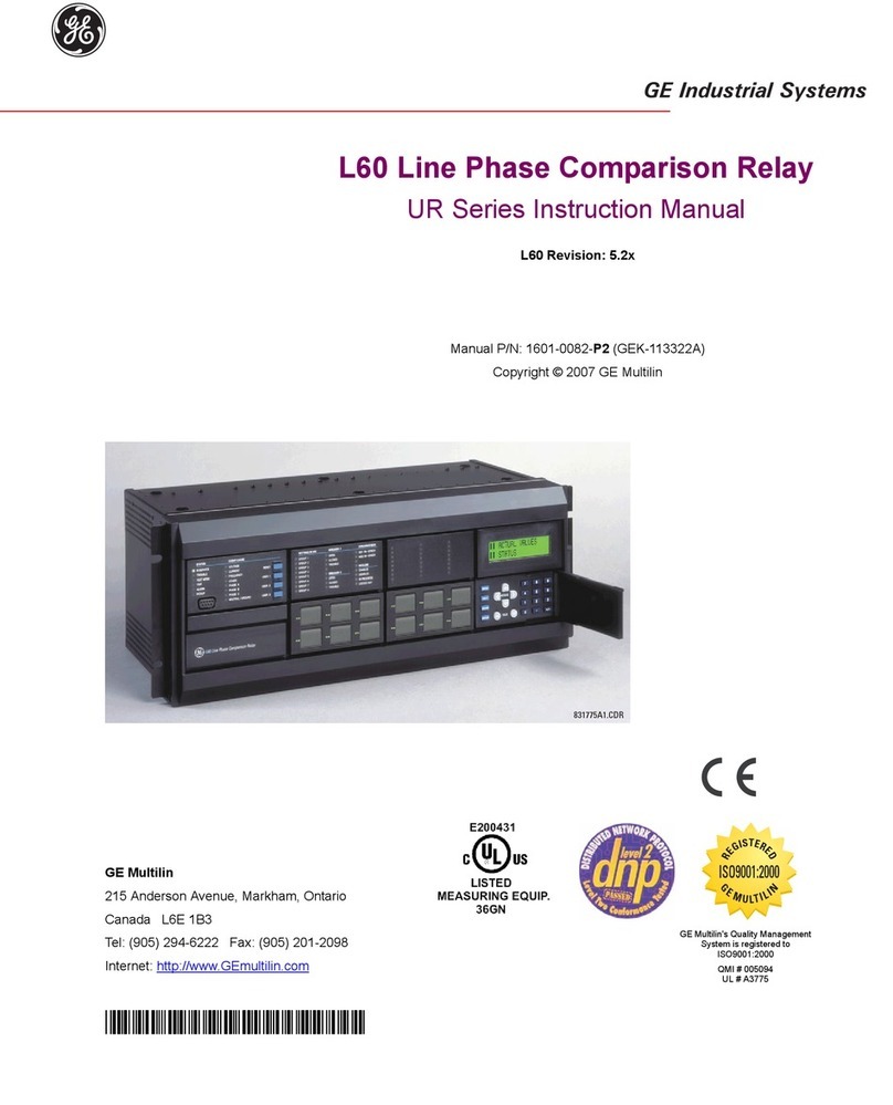
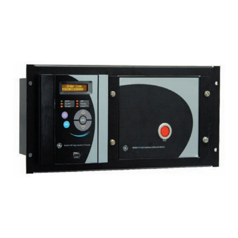
GE MiCOM P40 Agile User manual

GE
Grid Solutions
MiCOM P40 Agile
P446SV
Technical Manual
Distance Protection IED
Hardware Version: P
Software Version: 80
Publication Reference: P446SV-TM-EN-1


Contents
Chapter 1 Introduction 1
1 Chapter Overview 3
2 Foreword 4
2.1 Target Audience 4
2.2 Typographical Conventions 4
2.3 Nomenclature 5
2.4 Compliance 5
3 Product Scope 6
3.1 Product Versions 6
3.2 Ordering Options 7
4 Features and Functions 8
4.1 Distance Protection Functions 8
4.2 Protection Functions 8
4.3 Control Functions 9
4.4 Measurement Functions 9
4.5 Communication Functions 9
5 Logic Diagrams 11
6 Functional Overview 13
Chapter 2 Safety Information 15
1 Chapter Overview 17
2 Health and Safety 18
3 Symbols 19
4 Installation, Commissioning and Servicing 20
4.1 Lifting Hazards 20
4.2 Electrical Hazards 20
4.3 UL/CSA/CUL Requirements 21
4.4 Fusing Requirements 21
4.5 Equipment Connections 22
4.6 Protection Class 1 Equipment Requirements 22
4.7 Pre-energisation Checklist 23
4.8 Peripheral Circuitry 23
4.9 Upgrading/Servicing 24
5 Decommissioning and Disposal 25
6 Regulatory Compliance 26
6.1 EMC Compliance: 2014/30/EU 26
6.2 LVD Compliance: 2014/35/EU 26
6.3 R&TTE Compliance: 2014/53/EU 26
6.4 UL/CUL Compliance 26
6.5 ATEX Compliance: 2014/34/EU 26
Chapter 3 Hardware Design 29
1 Chapter Overview 31
2 Hardware Architecture 32
3 Mechanical Implementation 33
3.1 Housing Variants 33
3.2 List of Boards 34
4 Front Panel 35
4.1 40TE Front Panel 35
4.1.1 Front Panel Compartments 35
4.1.2 Keypad 36

4.1.3 Front Serial Port (SK1) 36
4.1.4 Front Parallel Port (SK2) 37
4.1.5 Fixed Function LEDs 37
4.1.6 Programable LEDs 37
5 Rear Panel 38
6 Boards and Modules 39
6.1 PCBs 39
6.2 Main Processor Board 40
6.3 Power Supply Board 41
6.3.1 Watchdog 43
6.3.2 Rear Serial Port 44
6.4 IEC61850-9-2LE Ethernet Board 45
6.5 Standard Output Relay Board 46
6.6 IRIG-B Board 47
6.7 Fibre Optic Board 48
6.8 Rear Communication Board 49
6.9 Ethernet Board 49
6.10 Redundant Ethernet Board 51
6.11 Coprocessor Board 53
6.11.1 Coprocessor board with 1PPS input 53
6.12 High Break Output Relay Board 54
Chapter 4 Software Design 57
1 Chapter Overview 59
2 Sofware Design Overview 60
3 System Level Software 61
3.1 Real Time Operating System 61
3.2 System Services Software 61
3.3 Self-Diagnostic Software 61
3.4 Startup Self-Testing 61
3.4.1 System Boot 61
3.4.2 System Level Software Initialisation 62
3.4.3 Platform Software Initialisation and Monitoring 62
3.5 Continuous Self-Testing 62
4 Platform Software 64
4.1 Record Logging 64
4.2 Settings Database 64
4.3 Interfaces 64
5 Protection and Control Functions 65
5.1 Acquisition of Samples 65
5.2 Frequency Tracking 65
5.3 Direct Use of Sample Values 65
5.4 Distance Protection 65
5.5 Fourier Signal Processing 66
5.6 Programmable Scheme Logic 67
5.7 Event Recording 67
5.8 Disturbance Recorder 68
5.9 Fault Locator 68
5.10 Function Key Interface 68
Chapter 5 Configuration 69
1 Chapter Overview 71
2 Settings Application Software 72
3 Using the HMI Panel 73
3.1 Navigating the HMI Panel 74
Contents P446SV
ii P446SV-TM-EN-1

3.2 Getting Started 74
3.3 Default Display 75
3.4 Default Display Navigation 76
3.5 Password Entry 77
3.6 Processing Alarms and Records 78
3.7 Menu Structure 78
3.8 Changing the Settings 79
3.9 Direct Access (The Hotkey menu) 80
3.9.1 Setting Group Selection Using Hotkeys 80
3.9.2 Control Inputs 81
3.9.3 Circuit Breaker Control 81
3.10 Function Keys 82
4 Line Parameters 84
4.1 Tripping Mode 84
4.1.1 CB Trip Conversion Logic Diagram 85
4.2 Residual Compensation 85
4.3 Mutual Compensation 86
5 Date and Time Configuration 88
5.1 Using an SNTP Signal 88
5.2 Using an IRIG-B Signal 88
5.3 Using an IEEE 1588 PTP Signal 88
5.4 Without a Timing Source Signal 89
5.5 Time Zone Compensation 89
5.6 Daylight Saving Time Compensation 90
6 Settings Group Selection 91
Chapter 6 Sampled Value Operation 93
1 Chapter Overview 95
2 Introduction To Sampled Values 96
3 Data Resampling 97
4 Sampled Value Alignment 98
4.1 Channel mappings for SAV Test, SAV Questionable, SAV Invalid 98
4.2 Data Quality 98
4.2.1 Impact of Data Quality on Protection Functions 99
4.3 Process Bus Performance 99
4.3.1 Sample Loss Data 100
4.4 VT Switching 100
4.5 Virtual Inputs and Outputs 101
4.5.1 P446, P546, P841B Virtual Inputs and Outputs DDBs 101
4.5.2 Virtual CT and VT Ratio Settings 101
4.6 IED Alarms 102
4.6.1 P446, P546, P841B Alarms 102
Chapter 7 Distance Protection 105
1 Chapter Overview 107
2 Introduction 108
2.1 Distance Protection Principle 108
2.2 Performance Influencing Factors 108
2.3 Impedance Calculation 109
2.4 Implementation with Comparators 109
2.5 Polarization of Distance Characteristics 109
3 Distance Measuring Zones Operating Principles 110
3.1 Mho Characteristics 111
3.1.1 Directional Mho Characteristic for Phase Faults 111
3.1.2 Offset Mho Characteristic for Phase Faults 111
P446SV Contents
P446SV-TM-EN-1 iii

3.1.3 Directional Self-Polarized Mho Characteristic for Earth Faults 112
3.1.4 Offset Mho Characteristic for Earth Faults 114
3.1.5 Memory Polarization of Mho Characteristics 116
3.1.6 Dynamic Mho Expansion and Contraction 116
3.1.7 Cross Polarization of Mho Characteristics 119
3.1.8 Implementation of Mho Polarization 120
3.2 Quadrilateral Characteristic 121
3.2.1 Directional Quadrilaterals 122
3.2.2 Quadrilateral Characteristic for Phase Faults 126
3.2.3 Earth Fault Quadrilateral Characteristics 130
4 Phase and Earth Fault Distance Protection Implementation 139
4.1 Phase Fault Characteristics 139
4.2 Earth Fault Characteristics 139
4.3 Distance Protection Tripping Decision 139
4.4 Distance Protection Phase Selection 140
4.4.1 Faulted Phase Selection 140
4.5 Biased Neutral Current Detector 141
4.6 Distance Element Zone Settings 142
4.6.1 Directionalizing the Distance Elements 142
4.6.2 Advanced Distance Zone Settings 143
4.6.3 Distance Zone Sensitivities 143
4.7 Capacitor VT Applications 144
4.7.1 CVTs with Passive Suppression of Ferroresonance 144
4.7.2 CVTs with Active Suppression of Ferroresonance 144
4.8 Load Blinding 145
4.9 Cross Country Fault Protection 146
5 Delta Directional Element 147
5.1 Delta Directional Principle and Setup 147
5.2 Delta Directional Decision 148
6 Application Notes 150
6.1 Setting Mode Choice 150
6.2 Operating Characteristic Selection 150
6.2.1 Phase Characteristic 150
6.2.2 Earth Fault Characteristic 151
6.3 Zone Reach Setting Guidelines 151
6.3.1 Quadrilateral Resistive Reaches 152
6.4 Earth Fault Resistive Reaches and Tilting 152
6.4.1 Dynamic Tilting 153
6.4.2 Fixed Tilting 154
6.5 Phase Fault Zone Settings 154
6.6 Directional Element for Distance Protection 155
6.7 Filtering Setup 155
6.7.1 Distance Digital Filter 155
6.7.2 Setting up CVTs 155
6.8 Load Blinding Setup 156
6.9 Polarizing Setup 156
6.10 Delta Directional Element Setting Guidelines 157
6.10.1 Delta Thresholds 157
6.11 Distance Protection Worked Example 157
6.11.1 Line Impedance Calculation 158
6.11.2 Residual Compensation for Earth Fault Elements 159
6.11.3 Zone 1 Phase and Ground Reach Settings 159
6.11.4 Zone 2 Phase and Ground Reach Settings 159
6.11.5 Zone 3 Phase and Ground Reach Settings 160
6.11.6 Zone 3 Reverse Reach Settings 160
6.11.7 Zone 4 Reverse Reach Settings 160
6.11.8 Load Avoidance 161
6.11.9 Quadrilateral Resistive Reach Settings 161
Contents P446SV
iv P446SV-TM-EN-1

6.12 Teed Feeder Applications 162
Chapter 8 Carrier Aided Schemes 165
1 Chapter Overview 167
2 Introduction 168
3 Carrier Aided Schemes Implementation 169
3.1 Carrier Aided Scheme Types 169
3.2 Default Carrier Aided Schemes 170
4 Aided Distance Scheme Logic 171
4.1 Permissive Underreach Scheme 171
4.2 Permissive Over-reach Scheme 172
4.2.1 Permissive Overreach Trip Reinforcement 174
4.2.2 Permissive Overreach Weak Infeed Features 175
4.3 Permissive Scheme Loss Of Guard 175
4.4 Current Reversal Guard Logic 176
4.5 Aided Distance Blocking Schemes 177
4.6 Aided Distance Unblocking Schemes 178
4.7 Aided Distance Logic Diagrams 180
4.7.1 Aided Distance Send Logic 180
4.7.2 Carrier Aided Schemes Receive Logic 180
4.7.3 Aided Distance Tripping Logic 181
4.7.4 PUR Aided Tripping logic 181
4.7.5 POR Aided Tripping logic 182
4.7.6 Aided Scheme Blocking 1 Tripping logic 183
4.7.7 Aided Scheme Blocking 2 Tripping logic 183
5 Aided DEF Scheme Logic 184
5.1 Aided DEF Introduction 184
5.2 Implementation 184
5.3 Aided DEF Polarization 184
5.3.1 Zero Sequence Polarizing 185
5.3.2 Negative Sequence Polarizing 186
5.4 Aided DEF Setting Guidelines 187
5.5 Aided DEF POR Scheme 188
5.6 Aided DEF Blocking Scheme 189
5.7 Aided DEF Logic Diagrams 190
5.7.1 DEF Directional Signals 190
5.7.2 Aided DEF Send Logic 191
5.7.3 Carrier Aided Schemes Receive Logic 191
5.7.4 Aided DEF Tripping Logic 192
5.7.5 POR Aided Tripping logic 193
5.7.6 Aided Scheme Blocking 1 Tripping logic 194
5.7.7 Aided Scheme Blocking 2 Tripping logic 194
6 Aided Delta Scheme Logic 195
6.1 Aided Delta POR Scheme 195
6.2 Aided Delta Blocking Scheme 196
6.3 Aided Delta Logic Diagrams 198
6.3.1 Aided Delta Send Logic 198
6.3.2 Carrier Aided Schemes Receive Logic 198
6.3.3 Aided Delta Tripping Logic 199
6.3.4 POR Aided Tripping logic 200
6.3.5 Aided Scheme Blocking 1 Tripping logic 201
6.3.6 Aided Scheme Blocking 2 Tripping logic 201
7 Application Notes 202
7.1 Aided Distance PUR Scheme 202
7.2 Aided Distance POR Scheme 202
7.3 Aided Distance Blocking Scheme 202
7.4 Aided DEF POR Scheme 203
P446SV Contents
P446SV-TM-EN-1 v

7.5 Aided DEF Blocking Scheme 203
7.6 Aided Delta POR Scheme 203
7.7 Aided Delta Blocking Scheme 203
7.8 Teed Feeder Applications 204
7.8.1 POR Schemes for Teed Feeders 205
7.8.2 PUR Schemes for Teed Feeders 205
7.8.3 Blocking Schemes for Teed Feeders 206
Chapter 9 Non-Aided Schemes 209
1 Chapter Overview 211
2 Non-Aided Schemes 212
3 Basic Schemes 213
3.1 Basic Scheme Modes 213
3.2 Basic Scheme Setting 215
4 Trip On Close Schemes 217
4.1 Switch On To Fault (SOTF) 218
4.1.1 Switch Onto Fault Mode 218
4.1.2 SOTF Tripping 219
4.1.3 SOTF Tripping with CNV 219
4.2 Trip On Reclose (TOR) 219
4.2.1 Trip On Reclose Mode 220
4.2.2 TOR Tripping Logic for Appropriate Zones 220
4.2.3 TOR Tripping Logic with CNV 220
4.3 Polarisation during Circuit Engergisation 220
5 Zone1 Extension Scheme 221
6 Loss of Load Scheme 222
Chapter 10 Power Swing Functions 225
1 Chapter Overview 227
2 Introduction to Power Swing Blocking 228
3 Power Swing Blocking 230
3.1 Power Swing Detection 230
3.1.1 Settings-Free Power Swing Detection 230
3.1.2 Slow Power Swing Detection 232
3.2 Detection of a Fault During a Power Swing 234
3.3 Power Swing Blocking Configuration 234
3.4 Power Swing Load Blinding Boundary 235
3.5 Power Swing Blocking Logic 236
3.6 Power Swing Blocking Setting Guidelines 237
3.6.1 Setting the Resistive Limits 238
3.6.2 Setting the Reactive Limits 238
3.6.3 PSB Timer Setting Guidelines 239
4 Out of Step Protection 241
4.1 Out of Step Detection 241
4.2 Out of Step Protection Operataing Principle 242
4.3 Out of Step Logic Diagram 243
4.4 OST Application Notes 243
4.4.1 Setting the OST Mode 243
Chapter 11 Autoreclose 249
1 Chapter Overview 251
2 Introduction to Autoreclose 252
3 Autoreclose Implementation 253
3.1 Autoreclose Logic Inputs from External Sources 254
3.1.1 Circuit Breaker Healthy Input 254
Contents P446SV
vi P446SV-TM-EN-1

3.1.2 Inhibit Autoreclose Input 254
3.1.3 Block Autoreclose Input 254
3.1.4 Reset Lockout Input 255
3.1.5 Pole Discrepancy Input 255
3.1.6 External Trip Indication 255
3.2 Autoreclose Logic Inputs 255
3.2.1 Trip Initiation Signals 255
3.2.2 Circuit Breaker Status Inputs 255
3.2.3 System Check Signals 255
3.3 Autoreclose Logic Outputs 255
3.4 Autoreclose Operating Sequence 256
3.4.1 AR Timing Sequence - Transient Fault 256
3.4.2 AR Timing Sequence - Evolving/Permanent Fault 256
3.4.3 AR Timing Sequence - Evolving/Permanent Fault Single-phase 257
3.4.4 AR Timing Sequence - Transient Fault Dual CB 257
3.4.5 AR Timing Sequence - Evolving/Permanent Fault Dual CB 258
3.4.6 AR Timing Sequence - Persistent Fault 259
4 Autoreclose System Map 261
4.1 Autoreclose System Map Diagrams 263
4.2 Autoreclose Internal Signals 272
4.3 Autoreclose DDB Signals 277
5 Logic Modules 289
5.1 Circuit Breaker Status Monitor 289
5.1.1 CB State Monitor 290
5.2 Circuit Breaker Open Logic 290
5.2.1 Circuit Breaker Open Logic Diagram 291
5.3 Circuit Breaker in Service Logic 291
5.3.1 Circuit Breaker in Service Logic Diagram 292
5.4 Autoreclose Enable Logic 292
5.4.1 Autoreclose Enable Logic Diagram 292
5.5 Autoreclose Leader/Follower 292
5.5.1 Leader/Follower CB Selection Logic Diagram 293
5.5.2 Leader Follower Logic Diagram 294
5.6 Autoreclose Modes 295
5.6.1 Single-Phase and Three-Phase Autoreclose 295
5.6.2 Autoreclose Modes Enable Logic Diagram 296
5.7 AR Force Three-Phase Trip Logic 297
5.7.1 Force Three-Phase Trip Logic Diagram 297
5.8 Autoreclose Initiation Logic 298
5.8.1 Autoreclose Initiation Logic Diagram 299
5.8.2 Autoreclose Trip Test Logic Diagram 299
5.8.3 External Trip Logic Diagram for CB1 300
5.8.4 External Trip Logic Diagram for CB2 301
5.8.5 Protection Reoperation and Evolving Fault Logic Diagram 302
5.8.6 Fault Memory Logic Diagram 302
5.9 Autoreclose In Progress 302
5.9.1 Autoreclose In Progress Logic Diagram for CB1 303
5.9.2 Autoreclose In Progress Logic Diagram for CB2 304
5.10 Sequence Counter 304
5.10.1 Autoreclose Sequence Counter Logic Diagram 305
5.11 Autoreclose Cycle Selection 305
5.11.1 Single Phase Autoreclose Cycle Selection Logic Diagram 306
5.11.2 3-phase Autoreclose Cycle Selection 307
5.12 Dead Time Control 307
5.12.1 Dead Time Start Enable Logic Diagram 308
5.12.2 Single-phase Leader Dead Time Logic Diagram 309
5.12.3 3-phase Leader Dead Time Logic Diagram 310
5.12.4 Follower Enable Logic Diagram 311
P446SV Contents
P446SV-TM-EN-1 vii

5.12.5 Single-phase Follower Timing Logic Diagram 312
5.12.6 Three-phase Follower Timing Logic Diagram 313
5.13 Circuit Breaker Autoclose 313
5.13.1 Circuit Breaker Autoclose Logic Diagram 314
5.14 Reclaim Time 314
5.14.1 Prepare Reclaim Initiation Logic Diagram 315
5.14.2 Reclaim Time Logic Diagram 316
5.14.3 Succesful Autoreclose Signals Logic Diagram 317
5.14.4 Autoreclose Reset Successful Indication Logic Diagram 318
5.15 CB Healthy and System Check Timers 318
5.15.1 CB Healthy and System Check Timers Logic Diagram 319
5.16 Autoreclose Shot Counters 319
5.16.1 Autoreclose Shot Counters Logic Diagram 321
5.17 Circuit Breaker Control 322
5.17.1 CB Control Logic Diagram 322
5.18 Circuit Breaker Trip Time Monitoring 323
5.18.1 CB Trip Time Monitoring Logic Diagram 324
5.19 Autoreclose Lockout 325
5.19.1 CB Lockout Logic Diagram 326
5.20 Reset Circuit Breaker Lockout 327
5.20.1 Reset CB Lockout Logic Diagram 329
5.21 Pole Discrepancy 329
5.21.1 Pole Discrepancy Logic Diagram 330
5.22 Circuit Breaker Trip Conversion 330
5.22.1 CB Trip Conversion Logic Diagram 331
5.23 Monitor Checks for CB Closure 331
5.23.1 Voltage Monitor for CB Closure 332
5.23.2 Check Synchronisation Monitor for CB Closure 333
5.24 Synchronisation Checks for CB Closure 334
5.24.1 Three-phase Autoreclose Leader Check Logic Diagram 336
5.24.2 Three-phase Autoreclose Follower Check Logic Diagram 338
5.24.3 CB Manual Close System Check Logic Diagram 340
6 Setting Guidelines 341
6.1 De-ionising Time Guidance 341
6.2 Dead Timer Setting Guidelines 341
6.2.1 Example Dead Time Calculation 341
6.3 Reclaim Time Setting Guidelines 342
6.4 Autoreclose Shot Counters 342
Chapter 12 CB Fail Protection 345
1 Chapter Overview 347
2 Circuit Breaker Fail Protection 348
3 Circuit Breaker Fail Implementation 349
3.1 Circuit Breaker Fail Timers 349
3.2 Zero Crossing Detection 349
4 Circuit Breaker Fail Logic 351
4.1 Circuit Breaker Fail Logic - Part 1 351
4.2 Circuit Breaker Fail Logic - Part 2 352
4.3 Circuit Breaker Fail Logic - Part 3 353
4.4 Circuit Breaker Fail Logic - Part 4 354
5 Application Notes 355
5.1 Reset Mechanisms for CB Fail Timers 355
5.2 Setting Guidelines (CB fail Timer) 355
5.3 Setting Guidelines (Undercurrent) 356
Chapter 13 Current Protection Functions 357
Contents P446SV
viii P446SV-TM-EN-1

1 Chapter Overview 359
2 Phase Fault Overcurrent Protection 360
2.1 POC Implementation 360
2.2 Directional Element 360
2.3 POC Logic 362
3 Negative Sequence Overcurrent Protection 363
3.1 Negative Sequence Overcurrent Protection Implementation 363
3.2 Directional Element 363
3.3 NPSOC Logic 364
3.4 Application Notes 364
3.4.1 Setting Guidelines (Current Threshold) 364
3.4.2 Setting Guidelines (Time Delay) 364
3.4.3 Setting Guidelines (Directional element) 364
4 Earth Fault Protection 366
4.1 Earth Fault Protection Implementation 366
4.2 IDG Curve 366
4.3 Directional Element 367
4.3.1 Residual Voltage Polarisation 367
4.3.2 Negative Sequence Polarisation 368
4.4 Earth Fault Protection Logic 369
4.5 Application Notes 369
4.5.1 Residual Voltage Polarisation Setting Guidelines 369
4.5.2 Setting Guidelines (Directional Element) 369
5 Sensitive Earth Fault Protection 371
5.1 SEF Protection Implementation 371
5.2 EPATR B Curve 371
5.3 Sensitive Earth Fault Protection Logic 372
5.4 Application Notes 373
5.4.1 Insulated Systems 373
5.4.2 Setting Guidelines (Insulated Systems) 374
6 High Impedance REF 376
6.1 High Impedance REF Principle 376
7 Thermal Overload Protection 378
7.1 Single Time Constant Characteristic 378
7.2 Dual Time Constant Characteristic 378
7.3 Thermal Overload Protection Implementation 379
7.4 Thermal Overload Protection Logic 379
7.5 Application Notes 379
7.5.1 Setting Guidelines for Dual Time Constant Characteristic 379
7.5.2 Setting Guidelines for Single Time Constant Characteristic 381
8 Broken Conductor Protection 382
8.1 Broken Conductor Protection Implementation 382
8.2 Broken Conductor Protection Logic 382
8.3 Application Notes 382
8.3.1 Setting Guidelines 382
Chapter 14 Voltage Protection Functions 385
1 Chapter Overview 387
2 Undervoltage Protection 388
2.1 Undervoltage Protection Implementation 388
2.2 Undervoltage Protection Logic 389
2.3 Application Notes 390
2.3.1 Undervoltage Setting Guidelines 390
3 Overvoltage Protection 391
3.1 Overvoltage Protection Implementation 391
3.2 Overvoltage Protection Logic 392
P446SV Contents
P446SV-TM-EN-1 ix

3.3 Application Notes 393
3.3.1 Overvoltage Setting Guidelines 393
4 Compensated Overvoltage 394
5 Residual Overvoltage Protection 395
5.1 Residual Overvoltage Protection Implementation 395
5.2 Residual Overvoltage Logic 396
5.3 Application Notes 396
5.3.1 Calculation for Solidly Earthed Systems 396
5.3.2 Calculation for Impedance Earthed Systems 397
5.3.3 Setting Guidelines 398
Chapter 15 Frequency Protection Functions 399
1 Chapter Overview 401
2 Frequency Protection 402
2.1 Underfrequency Protection 402
2.1.1 Underfrequency Protection Implementation 402
2.1.2 Underfrequency Protection logic 403
2.1.3 Application Notes 403
2.2 Overfrequency Protection 403
2.2.1 Overfrequency Protection Implementation 403
2.2.2 Overfrequency Protection logic 404
2.2.3 Application Notes 404
3 Independent R.O.C.O.F Protection 405
3.1 Indepenent R.O.C.O.F Protection Implementation 405
3.2 Independent R.O.C.O.F Protection Logic 405
Chapter 16 Monitoring and Control 407
1 Chapter Overview 409
2 Event Records 410
2.1 Event Types 410
2.1.1 Opto-input Events 411
2.1.2 Contact Events 411
2.1.3 Alarm Events 411
2.1.4 Fault Record Events 412
2.1.5 Maintenance Events 412
2.1.6 Protection Events 412
2.1.7 Security Events 413
2.1.8 Platform Events 413
3 Disturbance Recorder 414
4 Measurements 415
4.1 Measured Quantities 415
4.2 Measurement Setup 415
4.3 Fault Locator 415
4.4 Opto-input Time Stamping 415
5 CB Condition Monitoring 416
5.1 Broken Current Accumulator 417
5.2 CB Trip Counter 418
5.3 CB Operating Time Accumulator 419
5.4 Excessive Fault Frequency Counter 420
5.5 Reset Lockout Alarm 421
5.6 CB Condition Monitoring Logic 422
5.7 Reset Circuit Breaker Lockout 423
5.7.1 Reset CB Lockout Logic Diagram 425
5.8 Application Notes 425
5.8.1 Setting the Thresholds for the Total Broken Current 425
5.8.2 Setting the thresholds for the Number of Operations 426
Contents P446SV
x P446SV-TM-EN-1

5.8.3 Setting the thresholds for the Operating Time 426
5.8.4 Setting the Thresholds for Excesssive Fault Frequency 426
6 CB State Monitoring 427
6.1 CB State Monitor 428
7 Circuit Breaker Control 429
7.1 CB Control using the IED Menu 429
7.2 CB Control using the Hotkeys 430
7.3 CB Control using the Function Keys 430
7.4 CB Control using the Opto-inputs 431
7.5 Remote CB Control 431
7.6 CB Healthy Check 432
7.7 Synchronisation Check 432
7.8 CB Control AR Implications 432
7.9 CB Control Logic Diagram 433
8 Pole Dead Function 435
8.1 Pole Dead Logic 435
9 System Checks 436
9.1 System Checks Implementation 436
9.1.1 VT Connections 436
9.1.2 Voltage Monitoring 437
9.1.3 Check Synchronisation 437
9.1.4 Check Syncronisation Vector Diagram 437
9.2 Voltage Monitor for CB Closure 439
9.3 Check Synchronisation Monitor for CB Closure 440
9.4 System Check PSL 442
9.5 Application Notes 442
9.5.1 Predictive Closure of Circuit Breakers 442
9.5.2 Voltage and Phase Angle Correction 442
Chapter 17 Supervision 445
1 Chapter Overview 447
2 Voltage Transformer Supervision 448
2.1 Loss of One or Two Phase Voltages 448
2.2 Loss of all Three Phase Voltages 448
2.3 Absence of all Three Phase Voltages on Line Energisation 448
2.4 VTS Implementation 449
2.5 VTS Logic 450
3 Current Transformer Supervision 452
3.1 CTS Implementation 452
3.2 Standard CTS Logic 453
3.3 CTS Blocking 453
3.4 Application Notes 453
3.4.1 Setting Guidelines 453
4 Trip Circuit Supervision 454
4.1 Trip Circuit Supervision Scheme 1 454
4.1.1 Resistor Values 454
4.1.2 PSL for TCS Scheme 1 455
4.2 Trip Circuit Supervision Scheme 2 455
4.2.1 Resistor Values 456
4.2.2 PSL for TCS Scheme 2 456
4.3 Trip Circuit Supervision Scheme 3 456
4.3.1 Resistor Values 457
4.3.2 PSL for TCS Scheme 3 457
Chapter 18 Digital I/O and PSL Configuration 459
P446SV Contents
P446SV-TM-EN-1 xi

1 Chapter Overview 461
2 Configuring Digital Inputs and Outputs 462
3 Scheme Logic 463
3.1 PSL Editor 464
3.2 PSL Schemes 464
3.3 PSL Scheme Version Control 464
4 Configuring the Opto-Inputs 465
5 Assigning the Output Relays 466
6 Fixed Function LEDs 467
6.1 Trip LED Logic 467
7 Configuring Programmable LEDs 468
8 Function Keys 470
9 Control Inputs 471
Chapter 19 Fibre Teleprotection 473
1 Chapter Overview 475
2 Protection Signalling Introduction 476
2.1 Unit Protection Schemes 476
2.2 Teleprotection Commands 476
2.3 Transmission Media and Interference 477
3 Fibre Teleprotection Implementation 478
3.1 Setting up the IM64 Scheme 478
3.1.1 Fibre Teleprotection Scheme Terminal Addressing 479
3.1.2 Setting up IM64 480
3.1.3 Two-Terminal IM64 Operation 480
3.1.4 Dual Redundant Two-Terminal IM64 Operation 480
3.1.5 Three-Terminal IM64 Operation 480
3.1.6 Physical Connection 481
4 IM64 Logic 485
5 Application Notes 487
5.1 Alarm Management 487
5.2 Alarm Logic 487
5.3 Two-ended Scheme Extended Supervision 488
5.4 Three-ended Scheme Extended Supervision 488
Chapter 20 Electrical Teleprotection 491
1 Chapter Overview 493
2 Introduction 494
3 Teleprotection Scheme Principles 495
3.1 Direct Tripping 495
3.2 Permissive Tripping 495
4 Implementation 496
5 Configuration 497
6 Connecting to Electrical InterMiCOM 499
6.1 Short Distance 499
6.2 Long Distance 499
7 Application Notes 500
Chapter 21 Communications 503
1 Chapter Overview 505
2 Communication Interfaces 506
3 Serial Communication 507
3.1 EIA(RS)232 Bus 507
3.2 EIA(RS)485 Bus 507
Contents P446SV
xii P446SV-TM-EN-1

3.2.1 EIA(RS)485 Biasing Requirements 508
3.3 K-Bus 508
4 Standard Ethernet Communication 510
4.1 Hot-Standby Ethernet Failover 510
5 Redundant Ethernet Communication 511
5.1 Supported Protocols 511
5.2 Parallel Redundancy Protocol 512
5.3 High-Availability Seamless Redundancy (HSR) 513
5.3.1 HSR Multicast Topology 513
5.3.2 HSR Unicast Topology 513
5.3.3 HSR Application in the Substation 514
5.4 Rapid Spanning Tree Protocol 515
5.5 Self Healing Protocol 516
5.6 Dual Homing Protocol 517
5.7 Configuring IP Addresses 519
5.7.1 Configuring the IED IP Address 520
5.7.2 Configuring the REB IP Address 520
5.8 PRP/HSR Configurator 522
5.8.1 Connecting the IED to a PC 523
5.8.2 Installing the Configurator 523
5.8.3 Starting the Configurator 523
5.8.4 PRP/HSR Device Identification 524
5.8.5 Selecting the Device Mode 524
5.8.6 PRP/HSR IP Address Configuration 524
5.8.7 SNTP IP Address Configuration 524
5.8.8 Check for Connected Equipment 524
5.8.9 PRP Configuration 524
5.8.10 HSR Configuration 525
5.8.11 Filtering Database 525
5.8.12 End of Session 526
5.9 RSTP Configurator 526
5.9.1 Connecting the IED to a PC 526
5.9.2 Installing the Configurator 527
5.9.3 Starting the Configurator 527
5.9.4 RSTP Device Identification 527
5.9.5 RSTP IP Address Configuration 528
5.9.6 SNTP IP Address Configuration 528
5.9.7 Check for Connected Equipment 528
5.9.8 RSTP Configuration 528
5.9.9 End of Session 529
5.10 Switch Manager 529
5.10.1 Installation 530
5.10.2 Setup 531
5.10.3 Network Setup 531
5.10.4 Bandwidth Used 531
5.10.5 Reset Counters 531
5.10.6 Check for Connected Equipment 531
5.10.7 Mirroring Function 532
5.10.8 Ports On/Off 532
5.10.9 VLAN 532
5.10.10 End of Session 532
6 Simple Network Management Protocol (SNMP) 533
6.1 SNMP Management Information Bases 533
6.2 Main Processor MIBS Structure 533
6.3 Redundant Ethernet Board MIB Structure 534
6.4 Accessing the MIB 538
6.5 Main Processor SNMP Configuration 538
7 Data Protocols 540
P446SV Contents
P446SV-TM-EN-1 xiii

7.1 Courier 540
7.1.1 Physical Connection and Link Layer 540
7.1.2 Courier Database 541
7.1.3 Settings Categories 541
7.1.4 Setting Changes 541
7.1.5 Event Extraction 541
7.1.6 Disturbance Record Extraction 543
7.1.7 Programmable Scheme Logic Settings 543
7.1.8 Time Synchronisation 543
7.1.9 Courier Configuration 544
7.2 IEC 60870-5-103 545
7.2.1 Physical Connection and Link Layer 545
7.2.2 Initialisation 546
7.2.3 Time Synchronisation 546
7.2.4 Spontaneous Events 546
7.2.5 General Interrogation (GI) 546
7.2.6 Cyclic Measurements 546
7.2.7 Commands 546
7.2.8 Test Mode 547
7.2.9 Disturbance Records 547
7.2.10 Command/Monitor Blocking 547
7.2.11 IEC 60870-5-103 Configuration 547
7.3 DNP 3.0 548
7.3.1 Physical Connection and Link Layer 548
7.3.2 Object 1 Binary Inputs 549
7.3.3 Object 10 Binary Outputs 549
7.3.4 Object 20 Binary Counters 550
7.3.5 Object 30 Analogue Input 550
7.3.6 Object 40 Analogue Output 551
7.3.7 Object 50 Time Synchronisation 551
7.3.8 DNP3 Device Profile 551
7.3.9 DNP3 Configuration 559
7.4 IEC 61850 560
7.4.1 Benefits of IEC 61850 561
7.4.2 IEC 61850 Interoperability 561
7.4.3 The IEC 61850 Data Model 561
7.4.4 IEC 61850 in MiCOM IEDs 562
7.4.5 IEC 61850 Data Model Implementation 563
7.4.6 IEC 61850 Communication Services Implementation 563
7.4.7 IEC 61850 Peer-to-peer (GOOSE) communications 563
7.4.8 Mapping GOOSE Messages to Virtual Inputs 563
7.4.9 Ethernet Functionality 564
7.4.10 IEC 61850 Configuration 564
7.4.11 IEC 61850 Edition 2 565
8 Read Only Mode 569
8.1 IEC 60870-5-103 Protocol Blocking 569
8.2 Courier Protocol Blocking 569
8.3 IEC 61850 Protocol Blocking 570
8.4 Read-Only Settings 570
8.5 Read-Only DDB Signals 570
9 Time Synchronisation 571
9.1 Demodulated IRIG-B 571
9.1.1 IRIG-B Implementation 571
9.2 SNTP 572
9.2.1 Loss of SNTP Server Signal Alarm 572
9.3 IEEE 1588 Precision time Protocol 572
9.3.1 Accuracy and Delay Calculation 572
9.3.2 PTP Domains 573
9.4 Time Synchronsiation using the Communication Protocols 573
Contents P446SV
xiv P446SV-TM-EN-1

Chapter 22 Cyber-Security 575
1 Overview 577
2 The Need for Cyber-Security 578
3 Standards 579
3.1 NERC Compliance 579
3.1.1 CIP 002 580
3.1.2 CIP 003 580
3.1.3 CIP 004 580
3.1.4 CIP 005 580
3.1.5 CIP 006 580
3.1.6 CIP 007 581
3.1.7 CIP 008 581
3.1.8 CIP 009 581
3.2 IEEE 1686-2007 581
4 Cyber-Security Implementation 583
4.1 NERC-Compliant Display 583
4.2 Four-level Access 584
4.2.1 Blank Passwords 585
4.2.2 Password Rules 586
4.2.3 Access Level DDBs 586
4.3 Enhanced Password Security 586
4.3.1 Password Strengthening 586
4.3.2 Password Validation 587
4.3.3 Password Blocking 587
4.4 Password Recovery 588
4.4.1 Password Recovery 588
4.4.2 Password Encryption 589
4.5 Disabling Physical Ports 589
4.6 Disabling Logical Ports 589
4.7 Security Events Management 590
4.8 Logging Out 592
Chapter 23 Installation 593
1 Chapter Overview 595
2 Handling the Goods 596
2.1 Receipt of the Goods 596
2.2 Unpacking the Goods 596
2.3 Storing the Goods 596
2.4 Dismantling the Goods 596
3 Mounting the Device 597
3.1 Flush Panel Mounting 597
3.2 Rack Mounting 598
4 Cables and Connectors 600
4.1 Terminal Blocks 600
4.2 Power Supply Connections 601
4.3 Earth Connnection 601
4.4 Watchdog Connections 601
4.5 EIA(RS)485 and K-Bus Connections 601
4.6 IRIG-B Connection 602
4.7 Opto-input Connections 602
4.8 Output Relay Connections 602
4.9 Ethernet Metallic Connections 602
4.10 Ethernet Fibre Connections 602
4.11 RS232 connection 603
4.12 Download/Monitor Port 603
P446SV Contents
P446SV-TM-EN-1 xv

4.13 GPS Fibre Connection 603
4.14 Fibre Communication Connections 603
5 Case Dimensions 604
5.1 Case Dimensions 40TE 604
Chapter 24 Commissioning Instructions 605
1 Chapter Overview 607
2 General Guidelines 608
3 Commissioning Test Menu 609
3.1 Opto I/P Status Cell (Opto-input Status) 609
3.2 Relay O/P Status Cell (Relay Output Status) 609
3.3 Test Port Status Cell 609
3.4 Monitor Bit 1 to 8 Cells 609
3.5 Test Mode Cell 610
3.6 Test Pattern Cell 610
3.7 Contact Test Cell 610
3.8 Test LEDs Cell 610
3.9 Test Autoreclose Cell 610
3.10 Static Test Mode 611
3.11 Loopback Mode 611
3.12 IM64 Test Pattern 612
3.13 IM64 Test Mode 612
3.14 Red and Green LED Status Cells 612
3.15 Using a Monitor Port Test Box 612
4 Commissioning Equipment 613
4.1 Recommended Commissioning Equipment 613
4.2 Essential Commissioning Equipment 613
4.3 Advisory Test Equipment 614
5 Product Checks 615
5.1 Product Checks with the IED De-energised 615
5.1.1 Visual Inspection 616
5.1.2 Current Transformer Shorting Contacts 616
5.1.3 Insulation 616
5.1.4 External Wiring 616
5.1.5 Watchdog Contacts 617
5.1.6 Power Supply 617
5.2 Product Checks with the IED Energised 617
5.2.1 Watchdog Contacts 617
5.2.2 Test LCD 618
5.2.3 Date and Time 618
5.2.4 Test LEDs 619
5.2.5 Test Alarm and Out-of-Service LEDs 619
5.2.6 Test Trip LED 619
5.2.7 Test User-programmable LEDs 619
5.2.8 Test Opto-inputs 619
5.2.9 Test Output Relays 619
5.2.10 Test Serial Communication Port RP1 620
5.2.11 Test Serial Communication Port RP2 621
5.2.12 Test Ethernet Communication 621
5.3 Secondary Injection Tests 622
5.3.1 Test Current Inputs 622
5.3.2 Test Voltage Inputs 622
6 Electrical Intermicom Communication Loopback 624
6.1 Setting up the Loopback 624
6.2 Loopback Test 624
6.2.1 InterMicom Command Bits 625
6.2.2 InterMicom Channel Diagnostics 625
Contents P446SV
xvi P446SV-TM-EN-1

6.2.3 Simulating a Channel Failure 625
7 Intermicom 64 Communication 626
7.1 Checking the Interface 626
7.2 Setting up the Loopback 627
7.3 Loopback Test 627
8 Setting Checks 628
8.1 Apply Application-specific Settings 628
8.1.1 Transferring Settings from a Settings File 628
8.1.2 Entering settings using the HMI 628
9 IEC 61850 Edition 2 Testing 630
9.1 Using IEC 61850 Edition 2 Test Modes 630
9.1.1 IED Test Mode Behaviour 630
9.1.2 Sampled Value Test Mode Behaviour 630
9.2 Simulated Input Behaviour 631
9.3 Testing Examples 631
9.3.1 Test Procedure for Real Values 632
9.3.2 Test Procedure for Simulated Values - No Plant 632
9.3.3 Test Procedure for Simulated Values - With Plant 633
9.3.4 Contact Test 634
10 Distance Protection 635
10.1 Single-ended Testing 635
10.1.1 Preliminaries 635
10.1.2 Zone 1 Reach Check 635
10.1.3 Zone 2 Reach Check 636
10.1.4 Zone 3 Reach Check 636
10.1.5 Zone 4 Reach Check 636
10.1.6 Zone P Reach Check 636
10.1.7 Resistive Reach 637
10.1.8 Load Blinder 637
10.2 Operation and Contact Assignment 637
10.2.1 Phase A 637
10.2.2 Phase B 637
10.2.3 Phase C 637
10.2.4 Time Delay Settings 638
10.3 Scheme Testing 638
10.3.1 Scheme Trip Test for Zone 1 Extension 639
10.3.2 Scheme Trip Tests for Permissive Schemes 639
10.3.3 Scheme Trip Tests for Blocking Scheme 639
10.3.4 Signal Send Test for Permissive Schemes 640
10.3.5 Signal Send Test for Blocking Scheme 640
10.3.6 Scheme Timer Settings 640
11 Delta Directional Comparison 641
11.1 Single-ended Testing 641
11.1.1 Preliminaries 641
11.1.2 Single-ended Injection Test 641
11.1.3 Forward Fault Preparation 641
11.2 Operation and Contact Assignment 642
11.2.1 Phase A 642
11.2.2 Phase B 642
11.2.3 Phase C 642
11.3 Delta Protection Scheme Testing 643
11.3.1 Signal Send Test for Permissive Schemes 643
11.3.2 Signal Send Test for Blocking Schemes 643
12 DEF Aided Schemes 644
12.1 Earth Current Pilot Scheme 644
12.1.1 Preliminaries 644
12.1.2 Perform the Test 644
12.1.3 Forward Fault Trip Test 645
P446SV Contents
P446SV-TM-EN-1 xvii

12.2 Scheme Testing 645
12.2.1 Signal Send Test for Permissive Schemes 645
12.2.2 Signal Send Test for Blocking Schemes 645
13 Out of Step Protection 646
13.1 OST Setting 646
13.2 Predictive OST Setting 647
13.3 Predictive and OST Setting 647
13.4 OST Timer Test 647
14 Protection Timing Checks 648
14.1 Overcurrent Check 648
14.2 Connecting the Test Circuit 648
14.3 Performing the Test 648
14.4 Check the Operating Time 648
15 System Check and Check Synchronism 650
15.1 Check Synchronism Pass 650
15.2 Check Synchronism Fail 650
16 Check Trip and Autoreclose Cycle 651
17 End-to-End Communication Tests 652
17.1 Remove Local Loopbacks 652
17.1.1 Restoring Direct Fibre Connections 652
17.1.2 Restoring C37.94 Fibre Connections 653
17.1.3 Communications using P59x Interface Units 653
17.2 Remove Remote Loopbacks 653
17.3 Verify Communication between IEDs 653
18 End-to-End Scheme Tests 655
18.1 Aided Scheme 1 655
18.1.1 Preparation at Remote End 655
18.1.2 Performing the Test 655
18.1.3 Channel Check in the Opposite Direction 655
18.2 Aided Scheme 2 655
19 Onload Checks 657
19.1 Confirm Current Connections 657
19.2 Confirm Voltage Connections 657
19.3 On-load Directional Test 658
20 Final Checks 659
21 Commmissioning the P59x 660
21.1 Visual Inspection 660
21.2 Insulation 660
21.3 External Wiring 660
21.4 P59x Auxiliary Supply 660
21.5 P59x LEDs 661
21.6 Received Optical Signal Level 661
21.7 Optical Transmitter Level 661
21.8 Loopback Test 662
Chapter 25 Maintenance and Troubleshooting 663
1 Chapter Overview 665
2 Maintenance 666
2.1 Maintenance Checks 666
2.1.1 Alarms 666
2.1.2 Opto-isolators 666
2.1.3 Output Relays 666
2.1.4 Measurement Accuracy 666
2.2 Replacing the Device 667
2.3 Repairing the Device 668
2.4 Removing the front panel 668
Contents P446SV
xviii P446SV-TM-EN-1
Other manuals for MiCOM P40 Agile
5
Table of contents
Other GE Relay manuals
Popular Relay manuals by other brands

HORNER
HORNER HE-XE102 quick start guide

Rievtech
Rievtech ELC Series user manual

ABB
ABB REU 523 Technical reference manual

VERIS INDUSTRIES, INC.
VERIS INDUSTRIES, INC. V100DC installation guide

LOVATO ELECTRIC
LOVATO ELECTRIC LVM40 manual

Schweitzer Engineering Laboratories
Schweitzer Engineering Laboratories SEL-387-0 instruction manual