INSTALLATION MANUAL
IP REMOTE MICROPHONE STATION
Thank you for purchasing TOA's IP Remote Microphone Station.
Please carefully follow the instructions in this manual to ensure long, trouble-free use of your equipment.
TABLE OF CONTENTS
1. SAFETY PRECAUTIONS ............................. 1
2. GENERAL DESCRIPTION ........................... 1
3. FEATURES ................................................... 1
4. INSTALLATION ............................................ 2
4.1. Desk-Top Installation ............................... 2
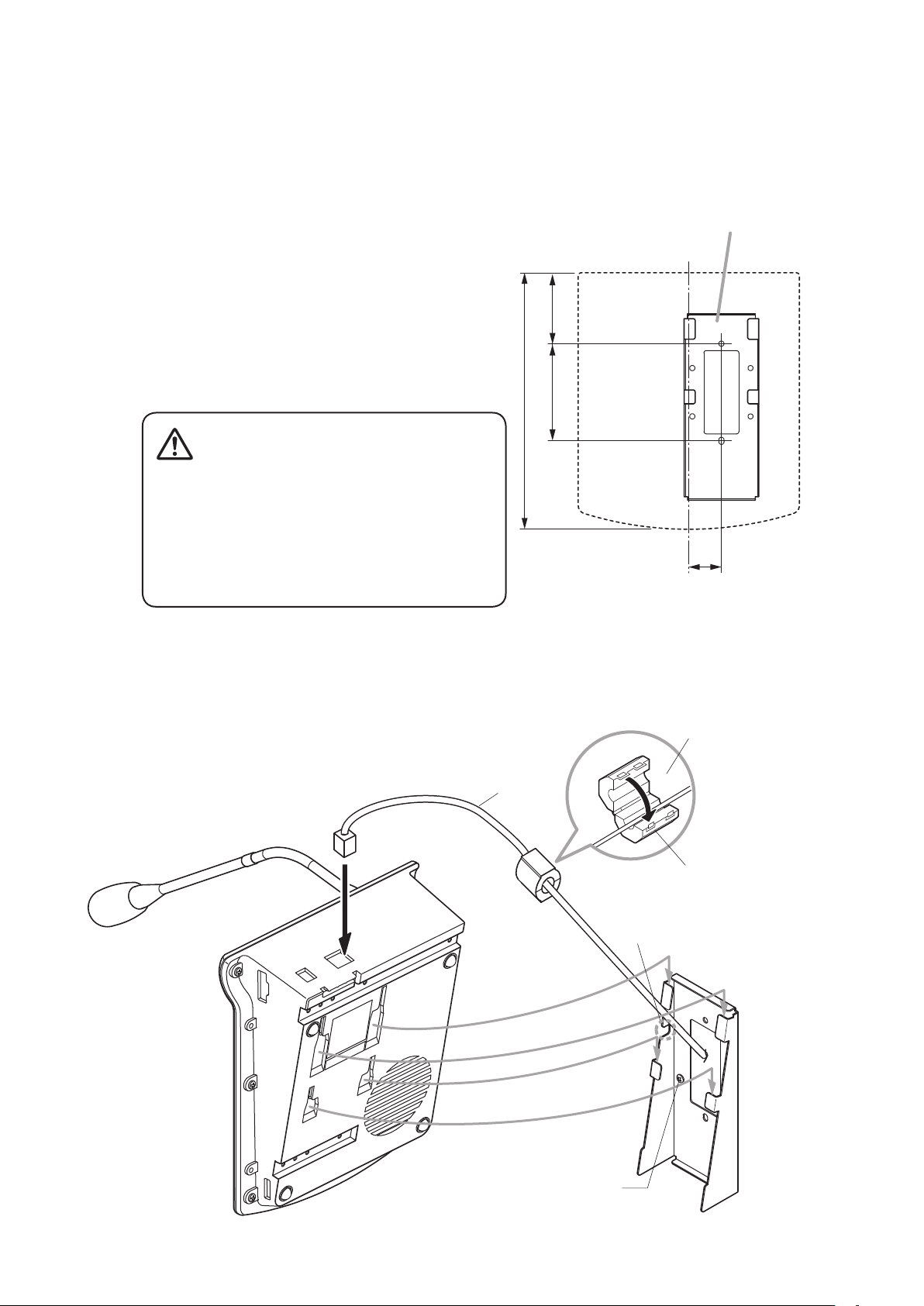
4.2. Wall Hanging .......................................... 3
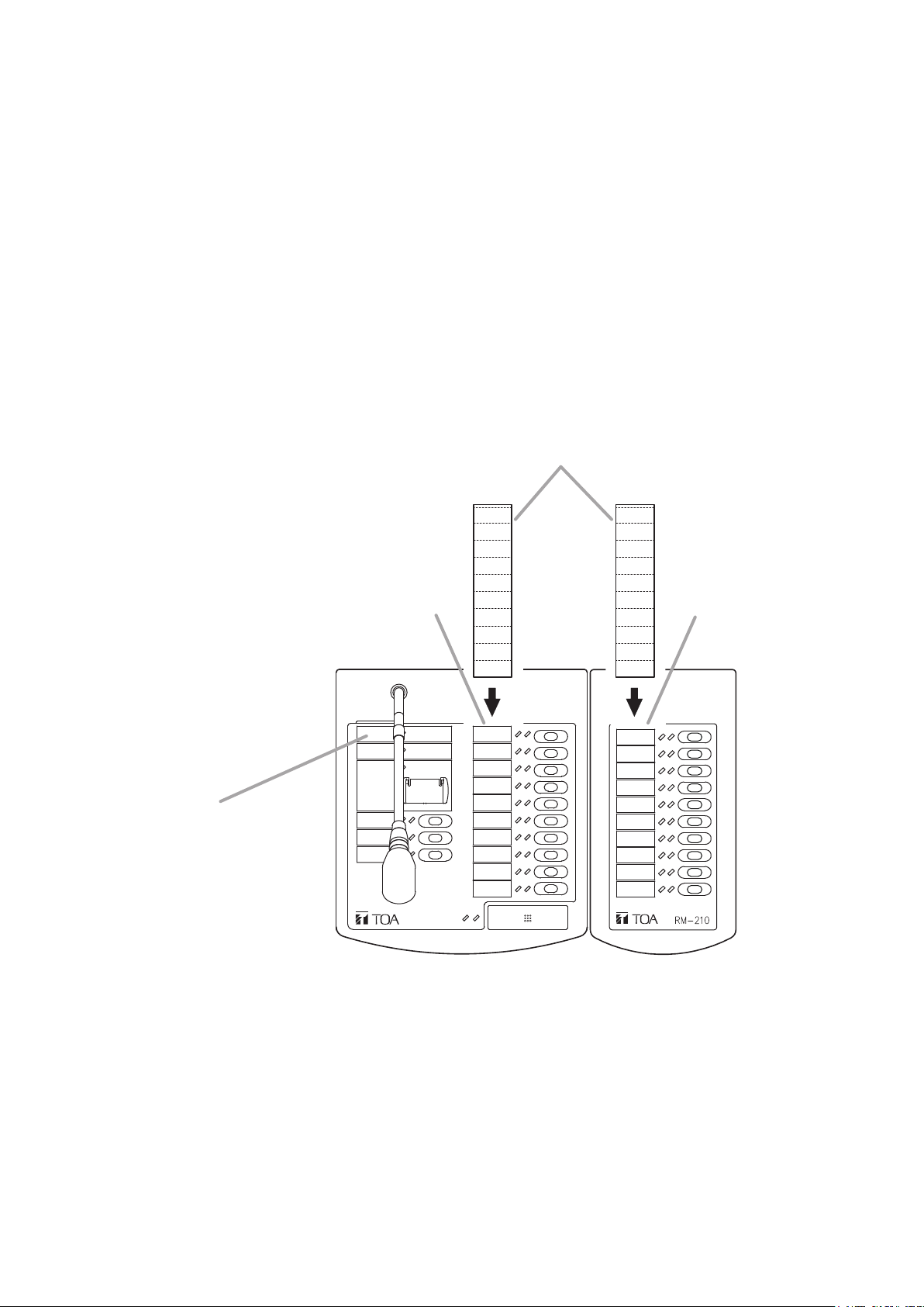
4.3. Creating Remote Microphone
Name Labels .......................................... 5
5. ACCESSORIES AND OPTIONAL
PRODUCTS .................................................. 8
5.1. Accessories ............................................ 8
5.2. Optional Products ................................... 8
1. SAFETY PRECAUTIONS
• Beforeinstallationoruse,besuretocarefullyreadalltheinstructions in thissection forcorrectandsafe
operation.
• Besuretofollowalltheprecautionaryinstructionsinthissection,whichcontainimportantwarningsand/or
cautions regarding safety.
• Afterreading,keepthismanualhandyforfuturereference.
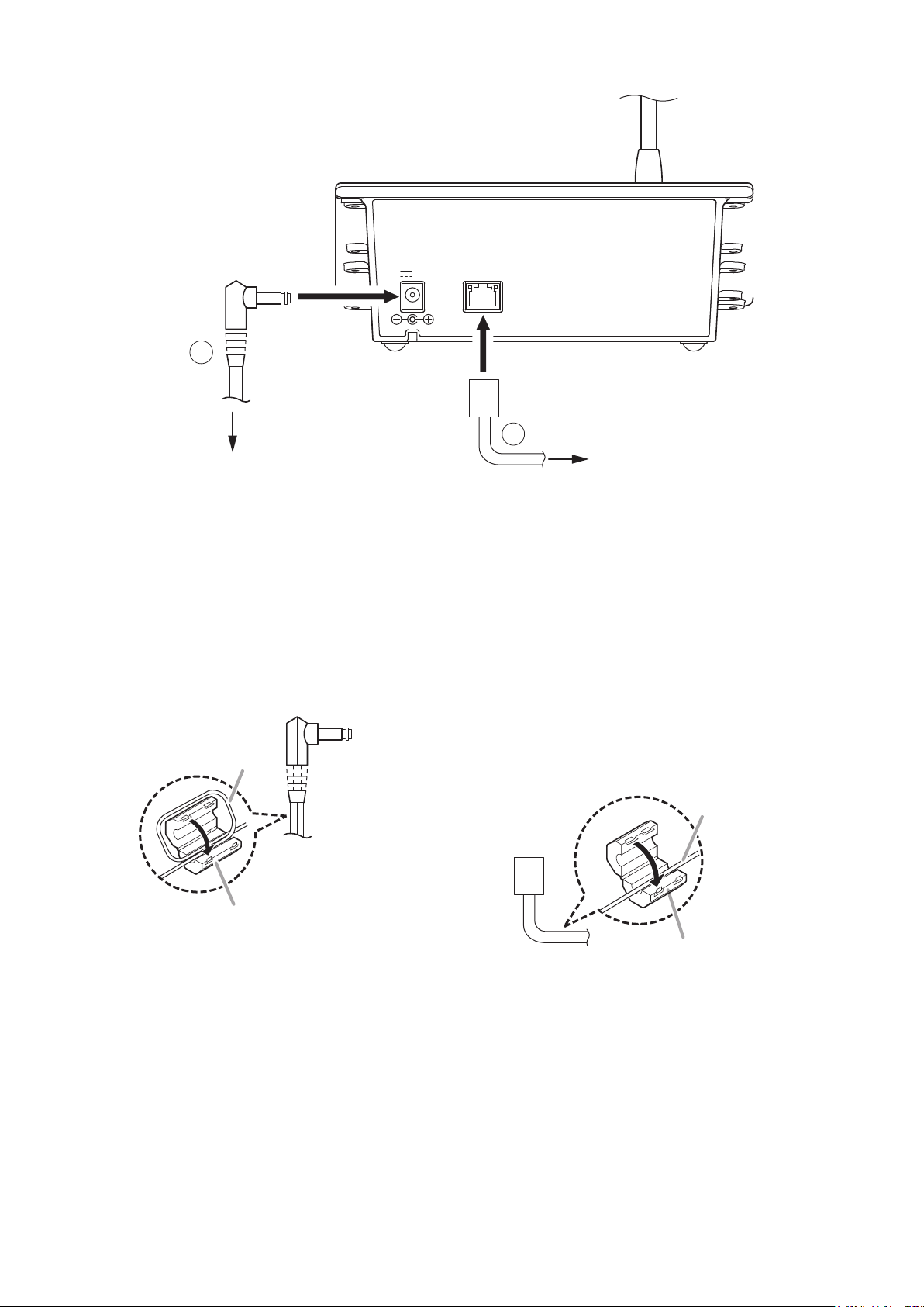
• UsethespeciedACadapterfortheunit.Notethattheuseofotheradaptermaycauseare.
2. GENERAL DESCRIPTION
The N-8610RM IP Remote Microphone Station is designed for use with TOA's packet intercom system (IP
network compatible intercom system) that employs the packet audio technology*.
ConnectingtheN-8610RMtoaLANorWANpermitsconversationsbetweenIPstationsandpaging.Usingthe
N-8610RM in combination with the SX-200IP IP Interface Module permits announcements to be made to the
SX-2000 Matrix System.
* Technology related to audio transmission over a network.
3. FEATURES
• Canbeconnectedtoanexistinglocalareanetwork(LAN)orwide-areanetwork(WAN).Thesystemcanalso
beeasilyconnectedtober-opticnetworkswithoutrestrictionsonoperatingdistance.
• ThededicatedN-8000softwareprogramenablescentralizedcontrolwithapersonalcomputer.
• Systemmaintenance (verifying operationlogand line supervision)canalso be performed witha PC and
Internet browser.
• ConnectingthestationtoaPoE(PoweroverEthernet)switchinghubeliminatestheneedforanACadapter.
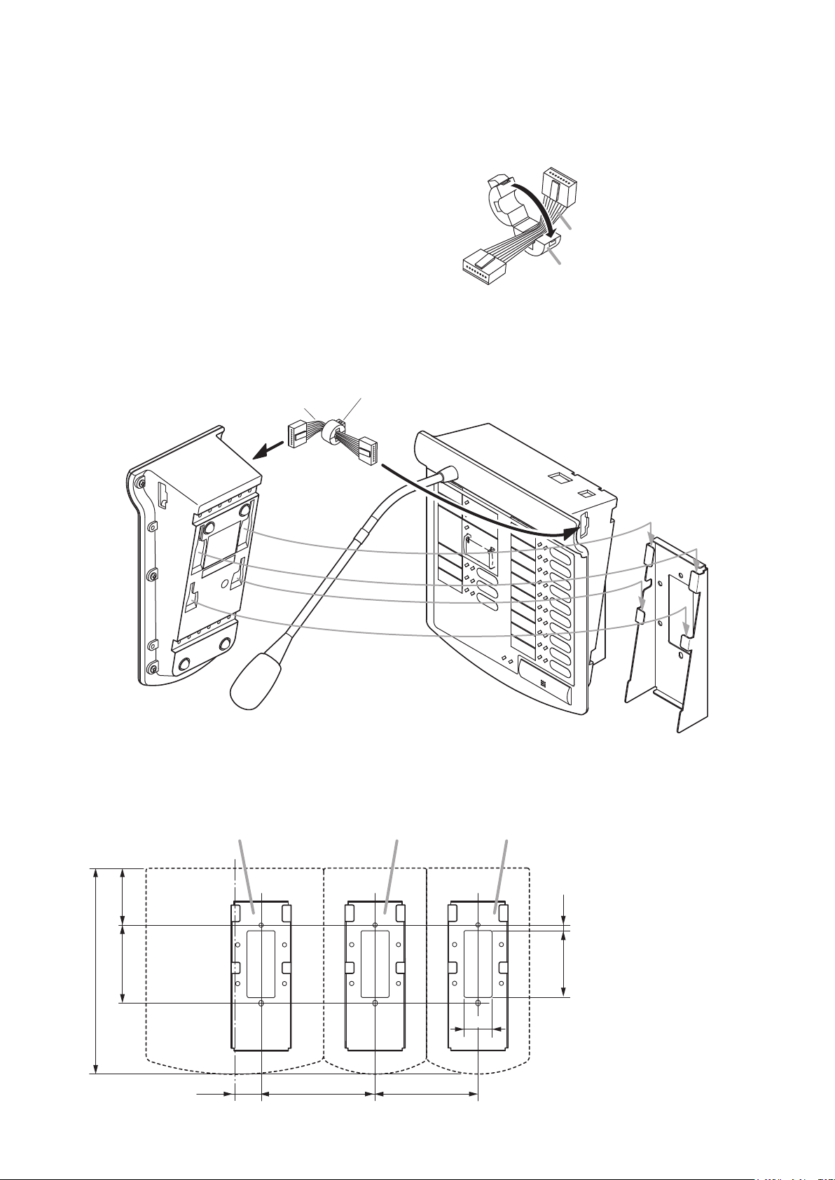
• ConnectinganoptionalRM-210RemoteMicrophoneExtensionexpandsthenumberoffunctionkeysand
indicatorsin10units.Upto4RM-210scanbeconnectedwhenanACadapterisused,andupto2RM-210s
inthecaseofPoEpowersupply.
• UsinganoptionalWB-RM200Wall-MountingBracket,thestationcanbemountedonawall.
N-8610RM
Indicatesapotentiallyhazardoussituationwhich,ifmishandled,could
resultinmoderateorminorpersonalinjury,and/orpropertydamage.
CAUTION
133-21-00001-00