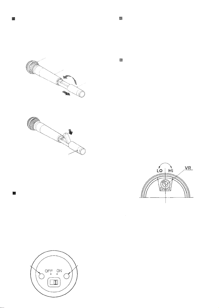
TIPS FOR CONVENIENT USE
1. Strength and direction of a radio signal to be
transmitted from the wireless microphone change
depending on the part of the microphone body to
be held by the hand. To prevent this, hold the
upper part of the body.
2. To avoid feedback, use the microphone with your
mouth put as close to the microphone top as
possible.
3. Adjust the tuner volume control to an appropriate
volume level that prevents feedback. The system is
prone to feedback if the microphone comes too
close to the speaker. It is suggested that tests be
performed preliminarily of feedback points in loca-
tions where the microphone is to be actually used.
4. To prevent radio interference or malfunction of the
tuner, always use the microphone at least 3m (10
feet) away from a receiving antenna.
5. When using multiple microphones simultaneously,
separate them at least 60cm (2 feet ) from each
other to prevent noise or break in sound, which
may result from mutual microphone interference.
6. Walls, floors, and ceilings block the radio wave's
straight-line travel, and frequently create null spots
that can cause temporary loss of signal reception
even within the practical transmission distance
threshold. In such cases, relocate a receiving
antenna or change microphone locations. (To
effectively reduce the null spots, use the diversity
tuner instead of non-diversity tuners.)
7. Human bodies absorb radio signals, and this can
badly affect signal reception. In rooms having a
number of people, attempt to install an antenna
high above the floor.
8. Once a wireless system is installed, actually move
around the site with a microphone to check system
operation.
9. Color Identification Labels
Identification labels of different colors are supplied
with the wireless microphone to simplify confir-
mation of microphone frequencies when multiple
microphones are in use. Attach one of the labels to
the microphone. In this event, both the microphone
and its corresponding receiver need to be in the
same color scheme for easy association with their
frequencies.
ADDITIONAL EXPLANATIONS
Squelch circuit
In a receiver employing only a noise or carrier
squelch, the squelch circuit is actuated and provides
the output whenever the receiver receives the same
RF carrier as a receiving frequency. This causes
even a disturbing radio signal to be received provided
its frequency is the same as the receiving frequency.
As a result, it can happen that sound is suddenly
heard from the speaker due to disturbing radio signal
even when the wireless microphone's power switch is
left OFF.
The squelch circuit of TOA's wireless systems con-
sists of both the tone and noise squelches, and is not
actuated if only same RF carrier as the receiving
frequency is received. It is so designed as to be
actuated and output a signal only when the received
RF carrier contains a very exact pre-determined tone
frequency component. Therefore, disturbing radio
signals are rejected and the speaker can be kept
completely quiet when the wireless microphone's
power switch is set to OFF, ensuring reliable use in
every application.
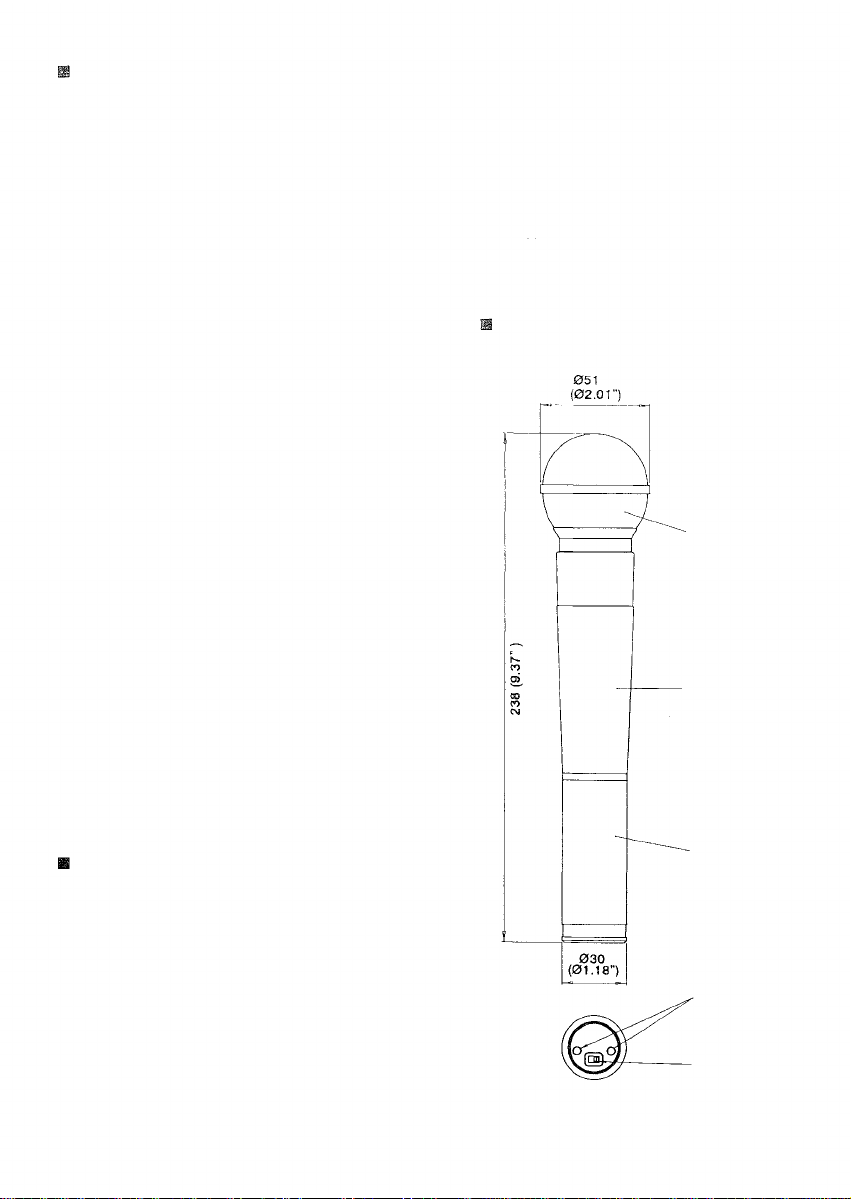
PART NAME
Microphone head
Body
Grip
Battery indicator
Power switch
Unit:mm(in.)