APPEARANCE AND DIMENSIONAL DIAGRAM
Unit: mm (in.)
ARCHITECTS AND ENGINEERS
SPECIFICATIONS
The mixer shall have two selectable monaural mic/line
inputs and four stereo line inputs; one stereo output and two
monaural outputs. The mixer shall have four mixing buses:
L/R stereo, and 1, 2 monaural. It shall incorporate all solid
state circuitry. Stereo and mono power outputs shall be
nominal +4dB (maximum +20dB), unbalanced (phone) at
less than 0.01%. Recording power output shall be nominal
-4dB (maximum +6dB), unbalanced (RCA pin) at less than
0.01%.
Inputs: CH 1, CH 2 mono XLR, balanced mic input shall be
nominal -60dB (maximum -30dB) 1k ohm input
impedance; XLR balanced mic (pad) input shall be nominal
-40dB (maximum -10dB) 1k ohm input impedance; and
unbalanced phone line input shall be nominal -10dB 10k
ohms input impedance. CH 3 to CH 6 (L/R stereo input)
shall be nominal -10dB 10k ohms input impedance
(unbalanced RCA pin + CH 6 parallel phone connection).
Stereo (L/M, R) and mono (1, 2) sub-inputs (unbalanced,
phone) shall be nominal +4dB (maximum +20dB) 50k
ohms input impedance. A-weighted noise levels shall be at
least -105dB below rated nominal output for Stereo Out
(L, R) and -98dB below rated nominal output for Mono Out
(1, 2) (all level controls minimum) and at least -94dB below
rated nominal output for Stereo Out (L, R), and -95dB below
rated nominal output for Mono Out (1, 2) (stereo, mono
(1, 2) max.). Frequency response shall be +1/-2dB from
20Hz to 20kHz at any power up to rated output.
Each of the two monaural inputs shall have both
microphone and line level input jacks with line priority if both
are connected; a compressor circuit to protect the mixer
from being driven into output clipping from excessive input
levels, a switchable high pass filter (HPF), and a -20dB pad
(PAD) in the microphone circuitry. The filter and pad
switches shall be internal to prevent tampering.
A sub-input shall be provided for each mixing bus for the
stereo and two mono outputs. A switchable On/Off muting
function shall automatically mute the stereo signals
assigned to the L/R stereo mix bus upon detection of a
useable signal in either monaural input channel. Each
mono output shall have an internal switch to change its
function to being a mono sum of the L/R stereo output. The
stereo output shall be provided with a low frequency
shelving equalizer of +/-15dB at 20Hz and a high
frequency shelving equalizer of +/-15dB at 20kHz.
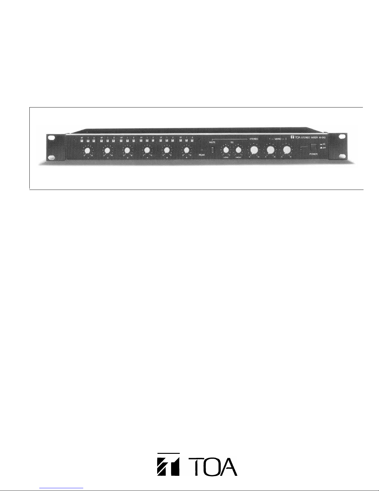
The front panel shall have: a power On/Off switch, six input
level controls; six sets of L/R three-input assignment
switches (L/R Stereo, Mono 1, Mono 2) with security cover;
auto-mute On/Off; low and high frequency equalizer
controls; three output level controls for L/R Stereo, Mono 1
and Mono 2; a power On/Off switch and power indicator.
The rear panel shall have: 1/4" and XLR jacks for inputs 1-2
(monaural), four pairs of RCA-type jacks for inputs 3-6
(stereo), plus two 1/4" L/R jacks for input 6; four pairs of
RCA-type jacks for the sub-inputs and record outputs; four
1/4" phone jacks for the L/R Stereo, Mono 1 and Mono 2
outputs; AC power input. The stereo sub-input jack shall
feed signal to left and right stereo outputs when only the L
input is connected.
An internal ground lift (GND) shall disconnect the audio
ground from the chassis in the LIFT position. Power shall
be by AC line mains. Power consumption for the 120V
version shall be 10W (12W 220/240V). The mixer shall be
enclosed in a durable, black enclosure. Overall dimensions
shall be 483.0(W) x 44.0(H) x 301.8(D)mm (19.0" x 1.7" x
11.9"). Weight shall be 3.8kg (8.4lbs.). Standard EIA
equipment rack mounting, operating instructions, 2 small
blue and 2 small red knobs, and 1 large blue and 1 large
red knobs shall be provided. The mixer shall be the TOA
model M-243.
NOTE; 0dB=0.775V RMS