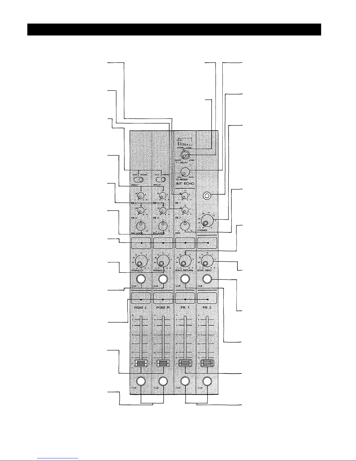
FB 1 Volume Control (FB1)
This control attenuates the echo-
return signals from the built-in echo
or an external echo unit and assigns
them to the FB 1 mixing bus.
FB 2 Volume Control (FB2)
This control attenuates the echo-
return signals from the built-in echo
or an external echo unit and assigns
them to the FB 2 mixing bus.
Stereo In ut Switches (INPUT)
Each switch has two positions, aux
and phono. The aux position accepts
line level signals such as tape
recorders. The phono position
provides direct input and RIAA
equalization for a turntable.
FB 1 Volume Control (FB1)
This control attenuates the stereo
input signals, mixes them to a
monaural signal, and assigns them
to the FB 1 mixing bus.
FB2 Volume Control (FB2)
This control attenuates the stereo
input signals, mixes them to a
monaural signal, and assigns them
to the FB 2 mixing bus.
Balance Control (BALANCE)
This control adjusts the level
balance of the stereo input signals
fed to the program L & R mixing
busses.
Writing Block
The name of the input equipment
can be written in with an eraseable
felt pen or a wax pencil.
Stereo In ut Volume Controls
(STEREO 1, STEREO 2)
These controls adjust the level of the
stereo in 1 and 2 signals to be fed to
the program L and R mixing busses.
Cue Switch (CUE)
The cue switch is for monitoring the
pre-fader signal in each stereo input
channel through headphone. This
feature is useful for cueing the start
of a tape or record.
Writing Block
The name of the input equipment or
microphone setting can be written in
with an eraseable felt pen or a wax
pencil,
Program Fader L and R
(PGM
L, PGM R)
The program faders control the
overall signal level of the program
mixes which are fed to the program
L & R outputs, and thus the output
level of the assigned internal power
amplifier.
Cue Switches (CUE)
The cue switch is for monitoring the
pre-fader program signals through
headphone. This is useful for
independent audition of the
program mixes.
Echo Time Control (T1 DELAY)
This control permits continuously
variable adjustment of the echo time
in either short or long ranges. The
short range is from 14m to 40m
seconds; the long range is from 40m
to 140m seconds.
Echo Time Switch
(SHORT, LONG)
The switch changes the echo time to
either the short or the long range.
Regeneration Control (T2 REGEN)
The T2 control is provided to adjust
the echo pattern (number of repeats)
of the internal analog delay.
Head hone Jack
The headphone jack will accept any
stereo headphone with 8 ohms
impedance, or higher.
Phones Level Control (PHONES)
The phones level control adjusts
both the program L and R signals fed
to the phones output and permits
stereo monitoring when the cue
switch is off. When the cue switch is
on, the control adjusts the corres-
ponding cue signal. When two or
more of the cue switches are on, the
control adjusts the corresponding
combined cue signals.
Pan Pot
(PAN)
The pan pot control assigns the
signals from the built-in echo or
external echo unit to the program L
and R.
Echo Return Volume Control
(ECHO RETURN)
This control sets the signal level
from the built-in echo or from an
external echo unit and sends it
(through the pan control) to the pro-
gram L and R.
Echo Send Volume Control
(ECHO SEND)
This control is provided to adjust
the overall signal level of the echo
mix to the echo send output, or to the
internal analog delay.
Cue Switch (CUE)
The cue switch is used for monitor-
ing the signal prior to the Echo/ end
volume control.
Cue Switch (CUE)
The cue switch is used for monitor-
ing the signal prior to the
Echo/Return volume control.
FB Fader 1 and 2 (FB1, FB2)
These faders control the overall
signal level of the mixes which are
fed to FB outputs 1 and 2.
Cue Switch (CUE)
The cue switch is used for monitor-
ing the signals prior to the FB 1 and 2
outputs.
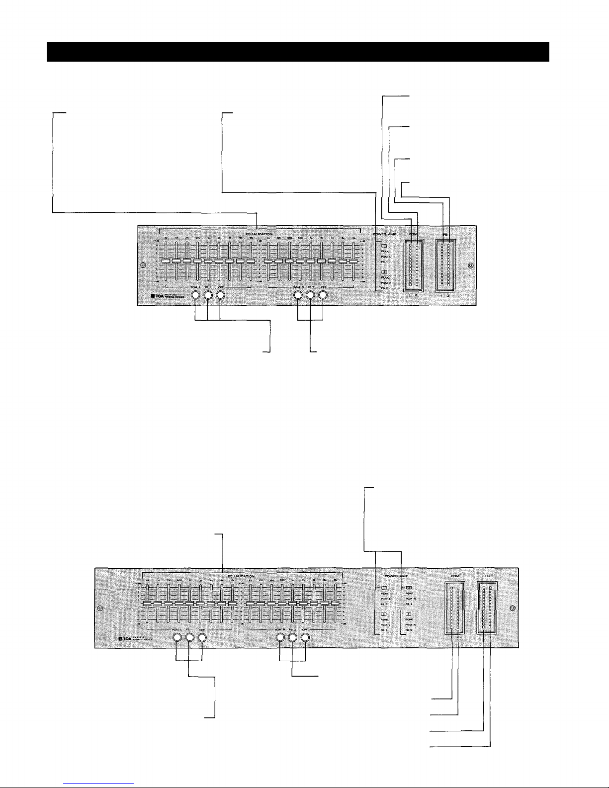
- 4 -
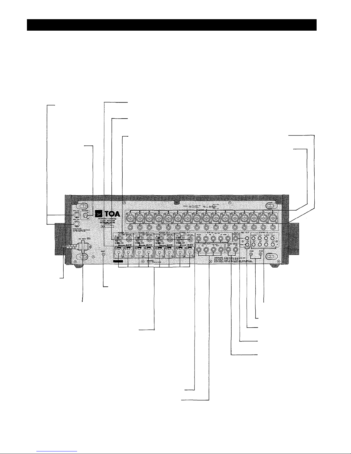
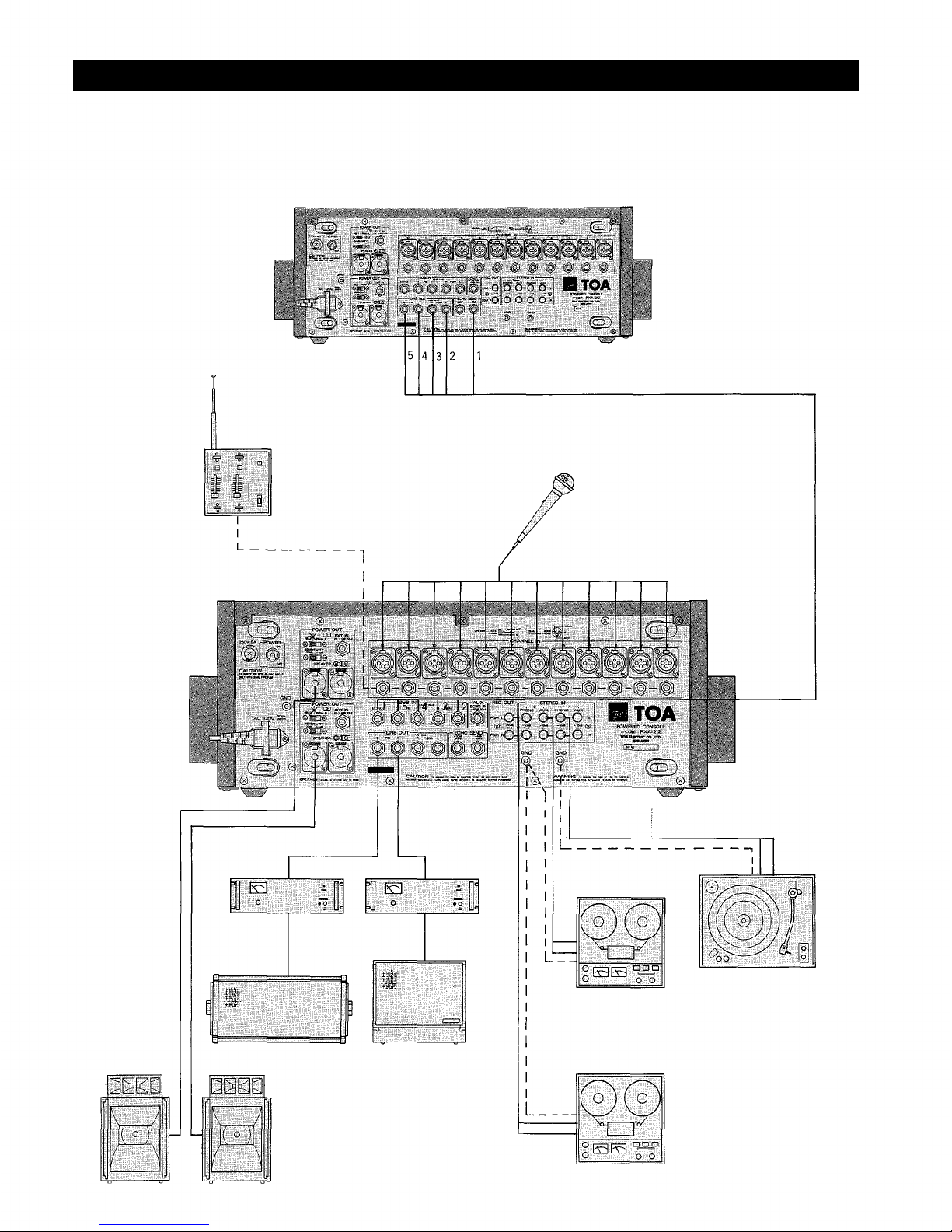
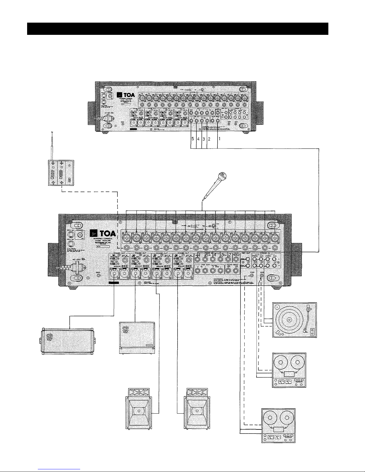
Front Panel, Out ut Section (RXA-212, RXA-216)