S82K
3
Note: 1. When a load is connected that has a built-in DC-DC converter, the overload protection may operate at startup and the power supply may not start.
Refer to Overload Protection on page 8 for details.
2. Use with DC voltage input is beyond the conditions of approval or conformance to applicable safety standards.
Do not use the Inverter output for the Power supply. Inverters with an output frequency of 50/60 Hz are available, but the rise in the internal temperature of
the Power Supply may result in ignition or burning. There is no polarity.
3. Defined with a 100% load and the rated input voltage (100 or 200 VAC.)
4. The output specification is defined at the power output terminals.
5. If the output voltage adjuster (V. ADJ) is turned, the voltage will increase by more than +10% of the voltage adjustment range. (+15% for S82K-03012/-03024)
When adjusting the output voltage, confirm the actual output voltage from the Power Supply and be sure that the load is not damaged.
6. Refer to Overload Protection on page 8 for details.
7. When using the 90-W model at an ambient temperature of 25°C or less, the overload protection function will operate at 101% to 111% of the rated output
current. When using the 90-W model at an ambient temperature exceeding 25°C, the overload protection function will operate at 92% to 111% of the rated
output current.
8. Parallel operation is set with the Parallel/Single Operation Selector.
9. To meet Class-2 requirements with the 100-W, either a fuse or circuit breaker that is UL listed or CSA certified, and rated at 4.2 A max. should be wired in
series with the load to be connected to the Power Supply. Only then can the Power Supply output be considered as meeting Class 2.
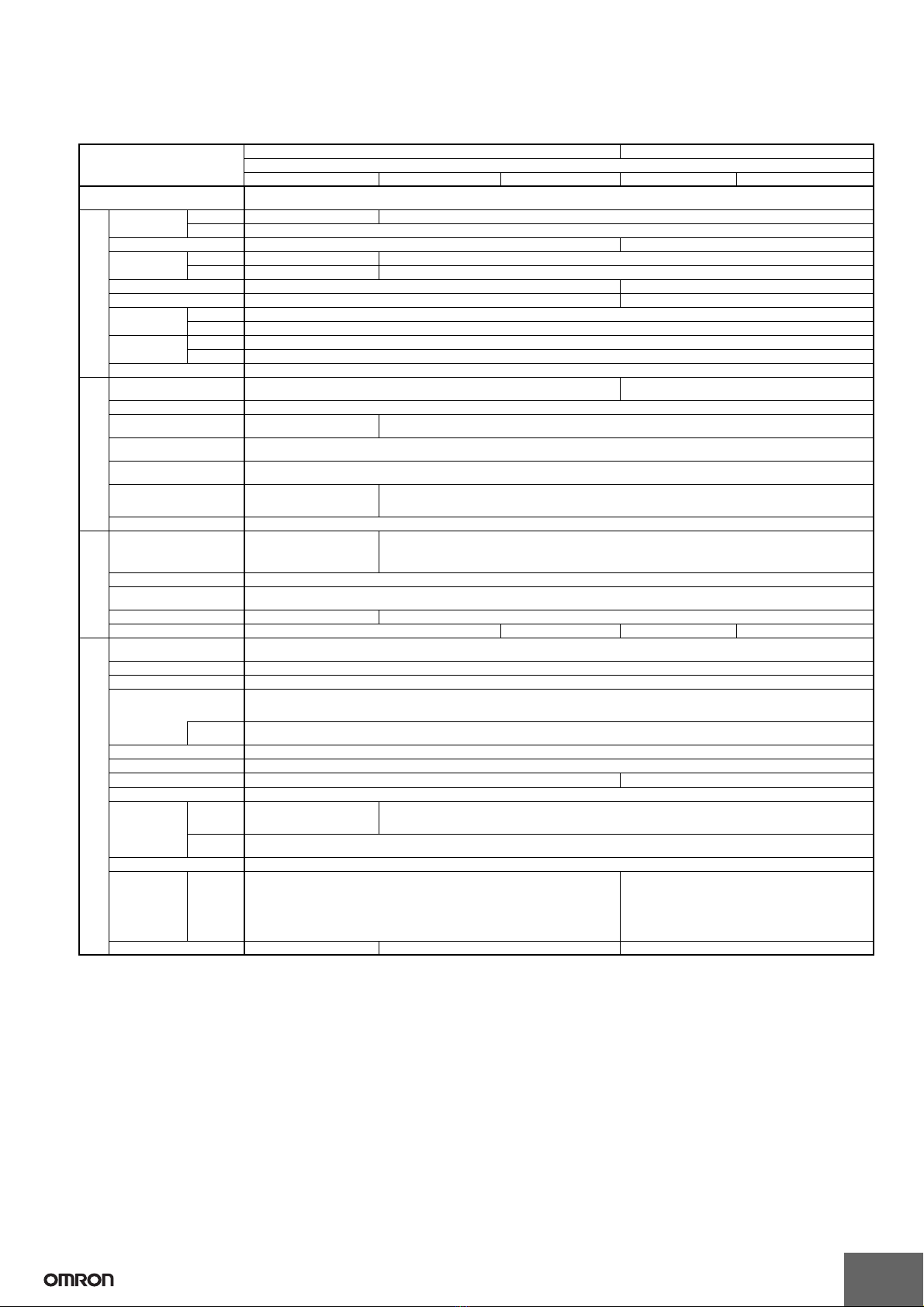
Power ratings
(See note 1.)
S82K S82K-P
Single output
Item 50 W 90 W 100 W 90 W 100 W
Efficiency (typical) 80% min. (Varies depending on specifications)
Input Voltage
(See note 2.)
AC 100 to 240 VAC (85 to 264 VAC) 100 V (85 to 132 VAC)/200 V (170 to 264 VAC) Selectable
DC Not possible
Frequency 50/60 Hz (47 to 450 Hz) 50/60 Hz (47 to 63 Hz)
Current
(See note 3.)
100-V input 1.3 A max. 2.5 A max.
200-V input 0.8 A max. 1.5 A max.
Power Factor --- 0.7 min. (at 200 VAC input, at rated output), 100 V: unlimited
Harmonic current emissions --- Conforms to EN6100-3-2 (200-V only)
Leakage current
(See note 3.)
100-V input 0.5 mA max.
200-V input 1 mA max.
Inrush current
(See note 3.)
100-V input 25 A max. (for cold start at 25°C)
200-V input 50 A max. (for cold start at 25°C)
Noise filter Ye s
Out-
put
(See
note
4.)
Voltage Adjustment Range ±10% (with V. ADJ) (−10% to 15% for S82K-05024) (See note 5.) ±10% (with V. ADJ) (See note 5.)
Ripple (See note 3.) 2% (p-p) max.
Input variation influence 0.5% max. (at 85 to 264 VAC in-
put, 100% load)
0.5% max. (at 85 to 132 VAC input /170 to 264 VAC input, 100% load)
Load variation influence
(rated input voltage)
1.5% max. (0 to 100% load)
Temperature variation influ-
ence (See note 3.)
0.05%/°C max.
Startup time 100 ms max. (up to 90% of out-
put voltage at rated input and
output)
200 ms max.
Hold time (See note 3.) 20 ms min.
Addi-
tion-
al
func-
tions
Overload protection
(See note 6.)
105% to 160% of rated load
current, gradual current in-
crease, voltage drop intermit-
tent operation, automatic reset
105% to 160% of rated load current, inverted L drop, automatic reset (See note 7.)
Overvoltage protection No
Undervoltage alarm indica-
tion
Yes (color: red)
Undervoltage alarm output No Yes
Parallel operation No Yes (up to 2 units.) No Yes (up to 2 units.) (See note 8.)
Oth-
er
Operating ambient tempera-
ture
Refer to the derating curve in Engineering Data. (with no icing or condensation)
Storage temperature −25 to 65°C (with no icing or condensation)
Operating ambient humidity 25% to 85% (Storage humidity: 25% to 90%)
Dielectric strength 3.0 kVAC for 1 min. (between all inputs and all outputs)
2.0 kVAC for 1 min. (between all inputs and PE terminals)
1.0 kVAC for 1 min. (between all outputs and PE terminals)
Detection
current
20 mA
Insulation resistance 100 MΩmin. (between all outputs and all inputs, PE terminals) at 500 VDC
Vibration resistance 10 to 55 Hz, 0.375-mm single amplitude for 2 h each in X, Y, and Z directions
Shock resistance 300 m/s2, 3 times each in ±X, ±Y, ±Z directions 150 m/s2, 3 times each in ±X, ±Y, ±Z directions
Output indicator Yes (color: green)
EMI Conducted
Emissions
Conforms to EN61204-3
EN55011 Class B and based
on FCC Class B
Conforms to EN61204-3 EN55011 Class B and based on FCC Class A
Radiated
Emissions
Conforms to EN61204-3 EN55011 Class B
EMS Conforms to EN61204-3 High severity levels
Approved stan-
dards
UL
cUL
cUR
EN/VDE
UL508 (Listing; Class 2: Per UL1310), Class 2 (excluding dual output models) (See note
9.), UL60950-1
CSA C22.2 No.14 (Class 2: Per No. 223, excluding dual output models) (See note 9.)
CSA No. 60950-1
EN50178 (= VDE0160), EN60950-1 (= VDE0805 Teil 1)
Based on VDE0106/P100
UL508 (Listing; Class 2: Per UL1310), Class 2 (excluding
dual output models) (See note 9.), UL60950-1
CSA C22.2 No.14 (Class 2: Per No. 223, excluding dual out-
put models) (See note 9.)
CSA No. 60950-1
EN50178 (= VDE0160), EN60950-1 (= VDE0805 Teil 1)
Based on VDE0106/P100
Weight 400 g max. 600 g max. 1000g max.