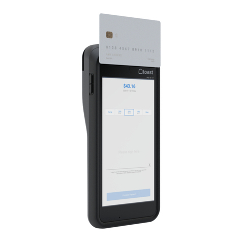
Toast Flex User manual

1
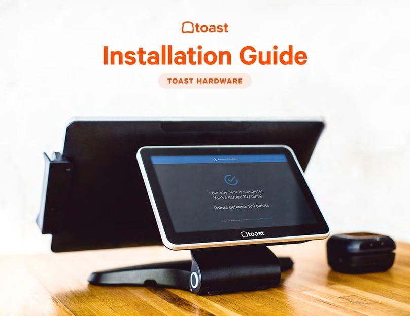
Installation Guide
TOAST HARDWARE

2
Welcome to the Toast family.
We’re so excited you’re here! Toast Hardware was developed to withstand the most
demanding restaurant conditions - spills, grease, and heat - so your restaurant is always
running at full speed. With a restaurant-grade structure, best-in-class processing speeds,
intuitive layout and sleek design, Toast Hardware makes it easier for you to run your
restaurant, delight guests and generate revenue.
Use this booklet to install your new Toast Hardware. We designed setup to be completed
within 30 minutes with intuitive, simple packaging, color-coded wiring and easy-to-follow
instructions. Have questions along the way? Contact Toast Customer Care.
Before Getting Started
Starting with a fresh surface
makes it easier to install!
Clean your counter,
make sure your counter space
is cleared and wiped down.
Unplug your current POS
hardware and remove it from
the counter so your counter
space is completely clear.
Wipe down the countertop
with the alcohol wipe
provided in your box.
Choose Your Bundle
You’ll follow the installation instructions for the hardware bundle you purchased.
TOAST FLEX + TOAST PRINTER TOAST FLEX + TOAST HUB TOAST FLEX TOAST FLEX FOR KITCHEN
Purchased a Toast Flex
terminal andToast Printer?
TURN TO PAGE 3
Purchased a Toast Flex
terminal andToast Hub?
TURN TO PAGE 8
Purchased just a
Toast Flex terminal?
TURN TO PAGE 13
Purchased a Toast Flex for Kitchen?
TURN TO PAGE 16 (On-Stand)
TURN TO PAGE 18 (Mounted)

3
Cabling Diagram
Toast Flex + Toast Printer
Use the cabling diagram as a guide for how
your system will be wired when it’s all set up.
Internet Cable
Toast Flex for Guest
Toast Flex
MSR Card Reader
(Only if user has a
Toast Flex for Guest)
Internet
Wall Outlet
Ethernet Cable
Power Brick
Toast Printer
USB-C
(Only if user has a
Toast Flex for Guest)
Toast Tap
(On-Counter)
Cash Drawer
Cash Drawer Kick
(CD-101)
USB-A to
Micro USB
Toast Printer
Connector Bay
If you are using direct attachment for Toast Flex for
Guest, this is already in place on the Toast Flex terminal.
For a full service restaurant, you will have the Toast Tap (Direct Attach
to Toast Flex) already in place instead of a Toast Tap (On-Counter).
! !
NOTE
If you have an additional
terminal, connect the
second power brick from the
base of the terminal stand
to the wall. Connect the
second ethernet cable from
the Toast Printer to the base
of the terminal stand.

4
Unpack your hardware:
Toast Flex + Toast Printer
1
Step 2
Step 4
Step 5
Step 3
Place near
wall outlet
2
3
4
5
Next, remove the orange box labeled “Power.”
This box contains the power adapter. Plug it into the
orange port labeled “Power In” on the Toast Printer.
Use the thumb screw to secure it.
Then, place the other end near the wall outlet, but don’t
plug it into the outlet yet. Placing it near the outlet now
will help you know where you want to coil or hide your
cables at the end of installation.
Next, remove the yellow box labeled “Connect.” This
box contains two yellow ethernet cables. One is 3 ft and
one is 7 ft. Choose the cord length that best suits your
restaurant and connect it from the wall to the yellow port
labeled “Internet IN” on the Toast Printer.
Take the red end of the USB-C cable and plug it into the
red “To Stand” port on the Toast Printer. Take the other
end and connect it to the orange port on the base of the
terminal stand.Use the thumb screw to secure it. Ensure
the thumbscrew is tight to avoid connectivity issues.
Unpack the Toast Printer first. It will contain a USB-C
to USB-C cable with a red end and an orange end.
It will also contain a wall mounting bracket, paper,
and a Toast TP200 Printer Quick Start Guide.
Unpack the Toast Flex terminal box next. This box has
two smaller boxes inside: an orange box and a yellow box.
Power
Adapter
Printer
Step 4
Step 5
Step 2

5
Plug the orange cord into the wall outlet. (From Step 3)
Then, hold the power button until the LED is blue. This
puts the printer into Sleep mode so you can configure it.
Hold the Feed button and the Power button at the same
time, then release the Power button. Your Toast Printer
will print out the printer’s test form and the blue LED will
turn green.
On the test form there will be an IP Address
(ex.192.168.192.169). The IP Address number will be used
to configure your Toast Printer in the Toast back-end.
B
A
C
B
A
Toast Flex + Toast Printer CONTINUED
Next, it’s time to load the printer paper! To do this:
6
7Configure your Toast Printer to start working! To do this:
Pull the latch on the front of the Toast Printer
and open the cover.
Insert the full size roll of 80 mm thermal
paper. The paper should exit on the opposite
side of the cover. See the images to the left
on how to position the paper correctly.
Close the Toast Printer cover.
NOTE This step must be completed.
After configuring your Toast Printer, the LED will be blue if the printer
is in Sleep mode. This happens if the printer is turned o or unplugged.
To power it back on, hold the Power button until the LED turns green.
For more information on this process, check out the
Creating a New Printer article in Toast Central.
Configure Toast Printer
Step 7b
Feed Button
Power Button
Step 7a
Green = Ready to print
Blue = Sleep Mode
Step 6b
Load Paper
C
Step 6B
Step 7B
Step 7C
! !

6
If you have a cash drawer, plug in the cash drawer
cable, which is grey with blue dots, from your
cash drawer to your Toast Printer.
If you have a wedge mount Toast Flex for Guest,
plug the green USB-C cable into the green
port labeled “GFD” on the terminal stand.
Toast Flex + Toast Printer
8
9
10
CONTINUED
NOTE
If you are using the direct
attachment for Toast Flex for
Guest, this is already in place
on the Toast Flex terminal.
(See image on the right)
Set up payment using one of the options below:
Direct Attach
B
AIf you are attaching your Toast Tap (On-Counter)
to the Toast Flex, open the purple box labeled
“Payments.” This box contains your Toast Tap
(On-Counter). Follow the instructions in the printed
guide for Micro USB to Micro USB.
If you have Toast Tap (Direct Attach to Toast Flex),
this will already be adhered to your Toast Flex
terminal.
Step 8
Step 9
Connector Bay
Wedge Mount
Step 8
Step 9
Wedge Mount
TIP
You can coil extra cable under the
Toast Flex for Guest connector bay.
!

7
Toast Flex + Toast Printer FINAL STEPS
Power on the Toast Flex terminal and follow
the Toast setup instructions that appear.
(See images on the left)
Log into your restaurant in the Toast App
and complete basic setup.
11
12
13
NOTE
You may need to update the Toast App
when you open it for the first time.
The last step is to turn on EMV. EMV must be turned
on to accept payment on your new Toast system.
See page 13 for EMV set up instructions.
TIP
Your new Toast Flex stand
can be raised higher or lower!
Power on your Toast Flex
Follow Toast setup instructions
Step 11
!
Step 12 Your Toast Flex + Toast Printer are set up!

8
Cabling Diagram
Toast Flex + Toast Hub
Use the cabling diagram as a guide for how
your system will be wired when it’s all set up.
NOTE
If you have a second
terminal, connect the second
power brick from the base of
the terminal stand to the wall.
Connect the second ethernet
cable from the Toast Hub
to the base of the terminal
stand.
If you are using direct attachment for Toast Flex for Guest,
this is already in place on the Toast Flex terminal.
For a full service restaurant, you will have the Toast Tap (Direct Attach
to Toast Flex) already in place instead of a Toast Tap (On-Counter).
Internet Cable
Internet Cable
Toast Flex
Toast Flex for Guest
USB-C
(Only if user has a
Toast Flex for Guest)
USB-A to Micro USB
Toast Tap
(On-Counter)
Wall Outlet
Internet
MSR Card Reader
(Only if user has a
Toast Flex for Guest)
Toast Hub
Power Brick
Ethernet Cable
Printer Power Cable
Epson Printer
!!

9
Unpack your hardware:
Toast Flex + Toast Hub
1
2
3
4
Next, remove the orange box labeled “Power.”
This box contains the power adapter. Plug it
into the orange port labeled “Power In” on the
Toast Hub. Use the thumb screw to secure it.
Ensure the thumbscrew is tight to avoid
connectivity issues.
Then, place the other end near the wall outlet,
but don’t plug it into the outlet yet. Placing it
near the outlet now will help you know where
you want to coil or hide your cables at the end
of installation.
Next, plug the yellow ethernet cable that was
packed in the Toast Hub box and connect
it from the Epson printer to the yellow port
labeled “Printer” on the Toast Hub.
Unpack the Epson Printer box first.
Unpack the Toast Hub box. This box contains three cables:
• Ethernet Cable (Yellow)
• USB-C - USB-C Cable (One end is red and one end is orange)
• Epson Power Cable (Pink with black stripes)
Unpack your Toast Flex terminal and place it on the counter.
This box has two smaller boxes inside:
An orange box and a yellow box.
Step 3
Place near
wall outlet
Step 4
Step 2
Hub
Step 4
Step 2

10
Remove the yellow box labeled “Connect.”
This box contains two ethernet cables.
One is 3 ft and one is 7 ft. Choose the cord
length that best suits your restaurant and
connect it from the wall to the yellow port
labeled “Printer” on the Toast Hub.
Plug the striped pink Epson power cable from
the Epson printer to the striped pink port
labeled “Printer In” on the Toast Hub.
Take the orange end of the USB-C cable and
plug it into the orange port in the base of the
Toast Flex terminal. Use the thumb screw to
secure it.
Take the red end of the USB-C cable and plug
it into the red port labeled “To Stand” on the
Toast Hub. Use the thumb screw to secure it.
This cable sends both data and power to your
Toast Flex terminal.
Step 5
Step 7
Step 8
Step 6
Toast Flex + Toast Hub
5
6
7
8
CONTINUED
Step 5
Step 7
Step 6
Step 8

11
If you have a cash drawer, plug in the cash drawer cable,
which is grey with blue dots, from your cash drawer to
the printer.
If you have a wedge mount Toast Flex for Guest, plug the
green USB-C cable into the green port labeled “GFD” on
the Toast Flex terminal stand.
Toast Flex + Toast Hub
9
10
11
CONTINUED
Set up payment using one of the options below:
B
AIf you are attaching your Toast Tap (On-Counter)
to the Toast Flex, open the purple box labeled
“Payments.” This box contains your Toast Tap
(On-Counter). Follow the instructions in the printed
guide for Micro USB to Micro USB.
If you have Toast Tap (Direct Attach to Toast Flex),
this will already be adhered to your Toast Flex
terminal.
TIP
You can coil extra cable under the
Toast Flex for Guest connector bay.
Step 9
Step 10
Connector Bay
Wedge Mount
!
NOTE
If you are using the direct
attachment for Toast Flex for
Guest, this is already in place
on the Toast Flex terminal.
(See image on the right)
Direct Attach

12
Toast Flex + Toast Hub FINAL STEPS
Now, plug in the orange power cord into the wall outlet.
(From Step 3)
Power on the Toast Flex terminal and follow the Toast
setup instructions that appear. (See images on the right.)
Log into your restaurant in the Toast App and complete
basic setup.
The last step is to turn on EMV. EMV must be turned
on to accept payment on your new Toast system.
See page 13 for EMV set up instructions.
12
13
14
TIP
Your new Toast Flex stand
can be raised higher or lower!
Power on your Toast Flex
Follow Toast setup instructions
Step 13
15
!
Step 14
Your Toast Flex + Toast Hub are set up!

13
Configuring EMV for your Toast System in the Toast App
Your Toast system is EMV capable.
EMV is a credit card payment process
that checks cards embedded with a
computer chip for their legitimacy. Enabling
EMV will allow for dipping and tapping of
credit cards on the Toast Tap.
Using the Toast icon in the upper left corner
of the screen on your Toast Flex, navigate to
the Setup menu and select Device Setup.
Scroll to the Payment Processing section
and select EMV Enabled.
Select Check for Updates to look for
updates to your card reader. If you do not
see an update, skip to the last step.
1 2
You’ll see the screen below as the update
processes. If you get an error message,
please try again in a few minutes.
Make sure to not let your session log out.
4
If the update was successful, you’ll see this
next screen. Toggle the switch to Yes, and
you’re all set!
5
Select Install Updates. The update normally
takes a few minutes to complete. If you
decline the update, you will not be able to use
EMV until this update is installed.
3

14
Unpack the Toast Flex terminal and place the terminal
on your counter.
Remove the yellow box labeled “Connect.” This box
contains two yellow ethernet cables. One cord is 3 ft and
one is 7 ft. Choose the cord length that best suits your
restaurant and connect it from the wall to the yellow port
labeled “Internet IN” on the base of the Toast Flex
terminal stand.
Remove the orange power box labeled “Power.” Plug in
the power cord from the wall into the orange port located
at the base of the Toast Flex terminal stand. Use the
thumb screw to secure it. Ensure the thumbscrew is
tight to avoid connectivity issues.
Set up payment using one of the options below:
Toast Flex
1
2
3
4
B
AIf you are attaching your Toast Tap (On-Counter)
to the Toast Flex, open the purple box labeled
“Payments.” This box contains your Toast Tap
(On-Counter). Follow the instructions in the
printed guide for Micro USB to Micro USB.
If you have Toast Tap (Direct Attach to Toast
Flex), this will already be adhered to your Toast
Flex terminal.
Step 3 Step 2
Thumb
Screw
Step 3 Step 2

15
Power on the Toast Flex and follow the Toast setup
instructions that appear on the screen.
Log into your restaurant in the Toast App and complete
basic setup. Note: You may need to update the Toast
App when you open it for the first time.
Toast Flex
5
6
CONTINUED
TIP
Your new Toast Flex stand
can be raised higher or lower!
Power on your Toast Flex
Follow Toast setup instructions
Step 5
!
NOTE
You may need to update the Toast App
when you open it for the first time.
Step 6
Your Toast Flex terminal is set up!

16
Toast Flex for Kitchen
Unpack your Toast Flex for Kitchen terminal
and place it on your counter.
Remove the yellow box labeled “Connect.” This box
contains two yellow ethernet cables. One cord is 3 ft
and one is 7 ft. Choose the cord length that best suits
your restaurant and connect it from the wall to the
yellow port labeled “Internet IN” on the base of the
terminal stand.
Remove the orange power box labeled “Power.” Plug
in the power adapter from the wall into the orange port
located at the base of the Toast Flex terminal stand.
Use the thumb screw to secure it.
1
2
3
ON-STAND
Step 3 Step 2
Thumb
Screw
Follow these instructions if the
Toast Flex for Kitchen will be on-stand
Before you get started, identify where you want
your Toast Flex for Kitchen to be located. Make
sure there is a power outlet and wall port in reach.
If you are using a wall mount for your
Toast Flex for Kitchen, go to the next page!
Step 3 Step 2

17
Step 4
Step 3
Toast Flex for Kitchen MOUNTED
Follow these instructions if the Toast Flex
for Kitchen will be mounted on the wall
Before you get started, identify where you want
your Toast Flex for Kitchen to be located. Make
sure there is a power outlet and wall port in reach.
Unpack your Toast Flex for Kitchen and Wall Mount:
1
2
It will have the swing arm for the wall mount
already attached.
It will also have the power cable and internet cable
pre-plugged into your Toast Flex for Kitchen.
Plug the other end of the internet cable into the wall port.
Attach your wall mount to the wall. (See note below.)
Plug the other end of the power cable into the wall outlet.
3
4
Toast does not drill holes. You will need
to drill your own holes or have holes
pre-drilled in the desired location.
!
Step 3
Step 2
Step 4

18
User Manual
• 14” Toast Flex->Model Name: TT200/TT200W
• 14” Toast Flex + Toast Flex for Guest with an 8” Screen for Guest attached->
Model Name: TT201/TT201W
• 14” Toast Flex for Kitchen -> Model Name TK200 / TK200W
Product Name: Data Processing Machine
Operation System
Processor
LCD
Memory
WIFI
Bluetooth
Camera
Speaker
External Ports
Power Adapter
Android 7.1
Rockchip ROK3399
14-inch, 1920 x 1080 resolution
16GB ROM + 4GB RAM
Dual-band WIFI, 802.11 a/b/g/n (2.4GHz/5GHz) supported
Bluetooth 4.0 BLE supported
5M FF MIPI Camera
2W
1 x RJ45 LAN port, 2x USB TypeC port, 1x HDMI-D port,
1x customized TypeC port, 3x Micro-USB port
Input: AC 100 24OV/2.5A Output: DC 24 V/4, OA
Specifications: Toast Flex
Toast Flex for Guest
LCD
Camera
External Ports
8-inch, 1280 x 800 resolution
5M FF USB Camera
1x Customized USB TypeC port, 2 x Micro-USB Port
It only takes a few steps to turn on this Toast Flex. Press the power button and
the screen will light up. Follow the instructions shown on the start-up screen.
Two internet access modes are available for you to select.
Simplified Setting
1. Press the [Setting] button and start WLAN to enter the WLAN search interface.
2. Search for the available WLAN hotspots.
3. Press the WLAN to be connected. If an encrypted network is selected,
a password is required for connection.
Wi-Fi Setting
Warning:
• Please insert the AC plug into the AC outlet according to the identifying input on the power adapter.
• It is prohibited to use the device in any places with potential explosive gases.
• Nonprofessionals should not open the power adapter to avoid danger.
• Adapter should be installed near the equipment and be easily accessible.
• The operating temperature of the device is between -10°C to 40°C.
Precautions
Recommendation:
• Do not use the device near water or in a humid environment.
• Keep liquid from falling on the Toast Flex.
• Do not use the device in extremely cold or hot environments, e.g. around fire or a lighted cigarette.
• Do not smash, throw, or bend the device.
• Use the device in a clean and dust free environment as much as possible and keep small items from
falling into the Toast Flex.
• Avoid installing or using during thunder and lightning; lightning strike may occur.
• Cut o the power immediately if there is abnormal smell, overheating, or smog.
Important Safety Instructions
The company is not responsible for the following behaviors:
• Damage caused by using and maintaining the device without following the User Manual.
• Damage or problems caused by selection of objects of consumables
(products which are not the initial ones
provided or recognized by the company).
In this case, the company will not undertake any responsibility. No one is entitled to modify
or change the product unless permitted by the company.
Statement
Discrepancies between the product and the file concerning details may occur due to product updates.
The company reserves the right to interpret the file and the right to revise this manual without prior notice.
• Please make sure the temperature for adapter is between -10°C to 40°C.
• Please make sure the temperature for device is between -10°C to 40°C.
Statement

19
This device complies with part 15 of the FCC Rules. Operation is subject to the following two conditions:
(1) This device may not cause harmful interference, and (2) this device must accept any interference
received, including interference that may cause undesired operation.
This device has been tested and found to comply with the limits for a Class B digital device, pursuant
to Part 15 of the FCC Rules. These limits are designed to provide reasonable protection against harmful
interference in a residential installation. This equipment generates, uses, and can radiate radio frequency
energy and, if not installed and used in accordance with the instructions, may cause harmful interference
to radio communications. However, there is no guarantee that interference will not occur in a particular
installation. If this equipment does cause harmful interference to radio or television reception, which can
be determined by turning the equipment o and on, the user is encouraged to try to correct the interfer-
ence by one or more of the following measures:
• Reorient or relocate the receiving antenna.
• Increase the separation between the equipment and receiver.
• Connect the equipment into an outlet or a circuit dierent from that to which the receiver is connected.
• Consult the dealer or an experienced radio/TV technician for help.
To comply with RF exposure requirements, a minimum separation distance of 20cm must be maintained
between the user’s body and the POS machine, including the antenna. Caution: Changes or modifications
not expressly approved by the party responsible for compliance could void the user’s authority to operate
the equipment.
FCC ID: 2AMNG-TT200, 2AB7X-CHB25, 2AB7X-CHB26
FCC Regulations
This device complies with the applicable industry Canada License exempt radio apparatus, the operation is
authorized under the conditions as follows: (1) this device may not cause interference, and (2) the user of
this device must accept any interference caused, even if the interference is likely to aect its performance.
Le présent appareil est conforme aux CNR d’Industrie Canada applicables aux appareils radio exempts de li-
cence. L’exploitation est autorisée aux deux conditions suivantes : (1) I’appareil ne doit pas produire de brouil-
lage, et (2) I’utilisateur de I’appareil doit accepter tout brouillage radioélectriquie subi, même si le brouillage
est susceptible d’en compromettre le fonctionnement. This device may not cause interference. This device
must accept any interference, including interference that may cause undesired operation of the device.
IC: 23177-TT200
IC Regulations
The manufacturer hereby declares that this device is in compliance with the essential
requirements and other relevant provisions of Radio Equipment Directive 2014/53/
EU. The description of accessories and components, including software, which allow
the radio equipment to operate as intended, can be obtained in the full text of the EU
declaration of conformity at the following internet address: https://pos.toasttab.com.
The Oicial Journal of the European Union Commission Decision of 12 February 2007
states that in the frequency band 5.150 to 5.350 GHz, wireless access systems (WAS),
including radio local area networks (RLANs), shall be restricted to indoor use.
EU Regulatory Conformance
Observe the national local regulations in the location where the device is to be used.
This device may be restricted for use in some or all member states of the European
Union (EU). Adapter shall be installed near the equipment and shall be easily accessible.
The device complies with RF specifications when the device is used 20cm from your
body. The product can be used across EU member states.
Notice
BE BG CZ DK DE EE IE EL ES FR
HR IT CY LV LT LU HU MT NT AT
PL PT RO SI SK FI SE UK
Max, radio-frequency
power transmitted
BT 2402-2480 MHz: 6 dBm
BLE 2402-2480 MHz: 5 dBm
2.4G WIFI 2412-2472 MHz: 15 dBm
5G WIFI 5150-5250 MHz: 12 dBm
5G WIFI 5725-5850 MHz: 12 dBm

20
Need Help With Troubleshooting?
Meet Your Success Team
We have teams of experts to support
your restaurant and ensure you and
your sta can focus on delighting
your guests.
Customer Care
Customer Care is your first line of defense
for all Toast questions. Our Customer Care
team is available 24/7/365 and is trained
to either help or route your request to the
correct team at Toast.
Call (617) 682-0225
Chat with an agent online
on Toast Central
Submit a ticket on Toast Central
Contact Toast Customer Care for any issues that may arise.
Check Out Your Resources
Whether you’re looking to master
Toast or you’re just getting started,
we’ve got you covered!
The goal of Restaurant Success is to
make sure you see the value of your
new POS. Whether it’s making sure that
you’re using all that Toast has to oer,
to answering questions about new Toast
updates, to helping you optimize your
technology.
Toast University is a free virtual training
tool available to all customers and their
employees. The guided courses will help
you train and ensure you get the most
out of your Toast POS.
Toast Central is a simple, searchable
online portal to find all your resources.
Use our knowledge base to get answers
to your top questions and learn more
about how to use Toast POS.
Sign in through central.toasttab.com Visit central.toasttab.com
Restaurant Success will contact
you directly once you’re live
with Toast!
University
Restaurant Success
Central
“Toast University looks great! I’d love
to have all of my new hires take all of
the tests and then, upon successful
completion, give them a raise.”
MARTIN, TASTE OF PHILLY
This manual suits for next models
3
Table of contents
Other Toast Touch Terminal manuals
Popular Touch Terminal manuals by other brands
UNIONCOMMUNITY
UNIONCOMMUNITY UBio-X Face Premium user guide
Advanced Card Systems
Advanced Card Systems eH880 Setup manual

Pyramid
Pyramid TimeTrax Clock reference guide

Mitsubishi Electric
Mitsubishi Electric GOT 1000 Series Training manual
Beckhoff
Beckhoff KL4011 operating instructions
Siemens
Siemens SiPass Entro Configuration manual

