AURES Odysse II User manual

U
s
e
r
Manua
l
Feb
ruar
y 2011
Revision 1.0

Cop
y
ri
ght 2011.
A
ll
R
i
ghts Rese
r
ved
Manua
l
Ve
r
s
i
on 1.0
The
i
nfo
r
mat
i
on conta
i
ned
i
n th
i
s document
i
s sub
j
ect to change w
i
thout not
i
ce.
We make no wa
rr
anty of any k
i
nd w
i
th
r
ega
r
d to th
i
s mate
ri
a
l
,
i
nc
l
ud
i
ng, but not
li
m
i
ted to,
the
i
mp
li
ed wa
rr
ant
i
es of me
r
chantab
ili
ty and f
i
tness fo
r
a pa
r
t
i
cu
l
a
r
pu
r
pose. We sha
ll
not
be
li
ab
l
e fo
r
e
rr
o
r
s conta
i
ned he
r
e
i
n o
r
fo
r
i
nc
i
denta
l
o
r
consequent
i
a
l
damages
i
n
connect
i
on w
i
th the fu
r
n
i
sh
i
ng, pe
r
fo
r
mance, o
r
use of th
i
s mate
ri
a
l
.
Th
i
s document conta
i
ns p
r
op
ri
eta
r
y
i
nfo
r
mat
i
on that
i
s p
r
otected by copy
ri
ght. A
ll
ri
ghts a
r
e
r
ese
r
ved. No pa
r
t of th
i
s document may be photocop
i
ed,
r
ep
r
oduced o
r
t
r
ans
l
ated to
anothe
r
l
anguage w
i
thout the p
ri
o
r
w
ri
tten consent of the manufactu
r
e
r
.
T
RAD
E
MARK
Inte
l
®, Pent
i
um® and MMX a
r
e
r
eg
i
ste
r
ed t
r
adema
r
ks of Inte
l
® Co
r
po
r
at
i
on. M
i
c
r
osoft®
and
r
eg
i
ste
r
ed t
r
adema
r
k of EL
O Touch Systems.

3
S
a
f
e
t
y
I
MP
O
R
TANT SAFETY INSTRUCTIONS
1.
Rea
d
t
hese ins
t
ruc
t
ions care
f
ully.
Save
t
hese ins
t
ruc
t
ions
f
or
f
u
t
ure re
f
erence.
2. Follow all warnings and ins
t
ruc
t
ions
marked on
t
he produc
t
.
3. Do no
t
use
t
his produc
t
near wa
t
er.
4. Do no
t
place
t
his produc
t
on an uns
t
able car
t
,s
t
and,or
t
able.The produc
t
may
f
all,
causing serious damage
t
o
t
he produc
t
.
5. Slo
t
s and openings in
t
he cabine
t
and
t
he back or bo
tt
om are provided
f
or
ven
t
ila
t
ion
;t
o ensure reliable opera
t
ion o
f
t
he produc
t
and
t
o pro
t
ec
t
i
t
f
rom
overhea
t
ing. These openings mus
t
no
t
be blocked or covered.The openings
should never be blocked by placing
t
he produc
t
on a bed, so
f
a, rug, or o
t
her
similar sur
f
ace.This produc
t
should never be placed near or over a radia
t
or or
hea
t
regis
t
er,or in a buil
t-
in ins
t
alla
t
ion unless proper ven
t
ila
t
ion is provided.
6. This produc
t
should be opera
t
ed
f
rom
t
he
t
ype o
f
power indica
t
ed on
t
he marking
label.I
f
you are no
t
sure o
f
t
he
t
ype o
f
power available, consul
t
your dealer or
local power company.
7. Do no
t
allow any
t
hing
t
o res
t
on
t
he power cord. Do no
t
loca
t
e
t
his produc
t
where
persons will walk on
t
he cord.
8. Never push objec
t
s o
f
any kind in
t
o
t
his produc
t
t
hrough cabine
t
slo
t
s as
t
hey
may
t
ouch dangerous vol
t
age poin
t
s or shor
t
ou
t
par
t
s
t
ha
t
could resul
t
in a
f
ire
or elec
t
ric shock.Never spill liquid o
f
any kind on
t
he produc
t
.
FCC
Th
i
s dev
i
ce co
mp
li
es
w
i
th pa
r
t 15 of the FCC
r
u
l
es.
Ope
r
at
i
on
i
s sub
j
ect to the fo
ll
ow
i
ng
two cond
i
t
i
ons:
(
1
)
Th
i
s dev
i
ce may not cause ha
r
mfu
l
i
nte
r
fe
r
ence
(
2
)
Th
i
s dev
i
ce must accept any
i
nte
r
fe
r
ence
r
ece
i
ved,
i
nc
l
ud
i
ng
i
nte
r
fe
r
ence that may
cause undes
ir
ed ope
r
at
i
on.
CE Mark
Th
i
s dev
i
ce comp
li
es w
i
th the
r
equ
ir
ements of the
EEC d
ir
ect
i
ve
2004/108/EC with regard to
Ŗ
Electromagnetic compatibility
ŗ
and 2006/95/EC
Ŗ
Low Voltage Directive
ŗ
.

4
C
a
u
t
ion on Li
t
hiu
m Ba
tt
e
ries
Dange
r
of e
xp
l
os
i
on
i
f batte
r
y
i
s
i
nco
rr
ect
l
y
r
ep
l
aced. Rep
l
ace on
l
y w
i
th the sa
me o
r
equ
i
va
l
ent type
r
ecommended by the manufactu
r
e
r
. D
i
sca
r
d used batte
ri
es acco
r
d
i
ng to
the manufacturer
ř
s instructions.
L
EGISLATION AND
WEEE SY
MBOL
2002/96/
E
C
Was
t
e Elec
t
rical a
nd Elec
t
ronic Equip
men
t
Direc
t
ive on
t
he
t
rea
t
men
t
,
collec
t
ion, recycling and disposal o
f
elec
t
ric and elec
t
ronic devices and
t
heir
componen
t
s.
The c
r
ossed dustb
i
n symbo
l
on the dev
i
ce means that
i
t shou
l
d not be d
i
sposed of w
i
th
othe
r
househo
l
d wastes at the end of
i
ts wo
r
k
i
ng
li
fe. Instead, the dev
i
ce shou
l
d be taken to
the waste co
ll
ect
i
on cent
r
es fo
r
act
i
vat
i
on of the t
r
eatment, co
ll
ect
i
on,
r
ecyc
li
ng and
d
i
sposa
l
p
r
ocedu
r
e.
To p
r
event poss
i
b
l
e ha
r
m to the env
ir
onment o
r
human hea
l
th f
r
om uncont
r
o
ll
ed waste
d
i
sposa
l
, p
l
ease sepa
r
ate th
i
s f
r
om othe
r
types of wastes and
r
ecyc
l
e
i
t
r
espons
i
b
l
y to
p
r
omote the susta
i
nab
l
e
r
euse of mate
ri
a
l
r
esou
r
ces.
Househo
l
d use
r
s shou
l
d contact e
i
the
r
the
r
eta
il
e
r
whe
r
e they pu
r
chased th
i
s p
r
oduct, o
r
the
ir
l
oca
l
gove
r
nment off
i
ce, fo
r
deta
il
s of whe
r
e and how they can take th
i
s
i
tem fo
r
env
ir
onmenta
ll
y safe
r
ecyc
li
ng.
Bus
i
ness use
r
s shou
l
d contact the
ir
supp
li
e
r
and check the te
r
ms and cond
i
t
i
ons of the
pu
r
chase cont
r
act.
Th
i
s p
r
oduct shou
l
d not be m
i
xed w
i
th othe
r
comme
r
c
i
a
l
wastes fo
r
d
i
sposa
l
.

5
T
ab
l
e
o
f
Con
t
en
t
s
1.
I
t
e
m
C
hecklis
t
.............................................................................................. 7
1.1.
Standa
r
d Ite
m
s............................................................................................ 7
1.2.
Opt
i
ona
l
Items ............................................................................................. 7
2.
Sys
t
em Vie
w................................................................................................. 9
2.1.
F
r
ont & S
i
de v
i
e
w......................................................................................... 9
2.2.
Rea
r
v
i
ew .................................................................................................... 9
2.3.
I
/O v
i
ew................................................................................................... 10
3.
Peripherals Ins
t
alla
t
ion ............................................................................. 11
3.1.
MSR ...........................................................................................................11
3.2.
Cash D
r
awe
r
Insta
ll
at
i
on............................................................................ 12
3.3.
VFD Custome
r
D
i
sp
l
ay.............................................................................. 14
3.4.
Second D
i
sp
l
ay Insta
ll
at
i
on........................................................................ 16
4.
RAID............................................................................................................ 19
4.1.
Int
r
oduct
i
on................................................................................................ 19
4.2.
Jumpe
r
Sett
i
ngs......................................................................................... 20
4.3.
Sett
i
ng RAID 1 Mode................................................................................. 20
4.4.
C
l
ea
ri
ng RAID 1 Mode............................................................................... 21
4.5.
Updat
i
ng f
r
om non RAID to RAID 1 ........................................................... 21
5.
Sys
t
em Disassembly................................................................................. 22
5.1.
Rep
l
ace HDD............................................................................................. 22
5.2.
Insta
ll
second HDD.................................................................................... 23
5.3.
Rep
l
ace I/O Boa
r
d..................................................................................... 24
5.4.
Rep
l
ace CD
-
ROM...................................................................................... 25
5.5.
Rep
l
ace Powe
r
Supp
l
y .............................................................................. 26
5.6.
Rep
l
ace Memo
r
y & CPU............................................................................ 27
5.7.
Remove Mothe
r
boa
r
d................................................................................ 28
5.8.
Remove the Inve
r
te
r
Boa
r
d........................................................................ 30
5.9.
Remove the Touch Pane
l
........................................................................... 31
6.
Jumper Se
tt
ings......................................................................................... 32
6.1.
Ma
i
n Boa
r
d Layout..................................................................................... 32
6.2.
Jumpe
r
Sett
i
ngs fo
r
Ma
i
n Boa
r
d................................................................. 33
6.3.
Connecto
r
s Locat
i
on.................................................................................. 36
6.4.
Connecto
r
s Def
i
n
i
t
i
on ................................................................................ 37

6
7.
De
f
a
ul
t
BI
O
S Se
tt
ings................................................................................ 38
7.1.
BI
OS Setup
Ut
ili
t
y...................................................................................... 38
7.2. Sta
r
t
i
ng the BIOS Setup............................................................................. 38
7.3.
When a P
r
ob
l
e
m Occu
r
s............................................................................ 38
7.4.
BIOS Ma
i
n Menu ....................................................................................... 39
8.
BIOS Upda
t
ing Procedure......................................................................... 41
Appendix A
:
Speci
f
ica
t
ion................................................................................ 42
Appendix B
:
Di
mensional Drawings ............................................................... 44
Appendix C
:
Drivers Ins
t
alla
t
ion ..................................................................... 46
Appendix D
:
Cus
t
omer Display Command Se
tt
ings...................................... 47

7
1
. I
t
e
m
C
heck
li
s
t
Ta
ke the syste
m un
i
t out of the ca
r
ton.
Remove the un
i
t f
r
om the ca
r
ton by ho
l
d
i
ng
i
t by the
foam
i
nse
r
ts. The fo
ll
ow
i
ng contents shou
l
d be found
i
n the ca
r
ton:
1.1.
Standa
r
d Ite
m
s
a.
Powe
r
Co
r
d
1.2.
Opt
i
ona
l
Items
a. Magnet
i
c Ca
r
d Reade
r
b.
i
Button Da
ll
as Key Reade
r
c. Magnet
i
c Ca
r
d
+
i
Button Da
ll
as Key Reade
r
d. RFID Reade
r

8
e.
B
i
o
met
ri
c
Reade
r
(
f
i
nge
r
p
ri
nt
)
f. Custome
r
D
i
sp
l
ay
(
V
FD
)
g. 2nd D
i
sp
l
ay

9
2
.
Sys
t
e
m
V
i
e
w
2.1.
F
r
ont
& S
i
de
v
i
e
w
2.2.Rea
r
v
i
ew

10
2.3.
I
/
O
v
i
e
w

11
3
.
Pe
ri
phe
r
a
l
s
I
ns
t
a
ll
a
ti
on
Opt
i
ona
l
pe
ri
phe
r
a
l
s
(r
efe
r
to page 7
-
8
)
a
r
e tested and can be supp
li
ed at you
r
r
equest.
The
M
S
R and VFD custome
r
d
i
sp
l
ay a
r
e packed sepa
r
ate
l
y fo
r
t
r
anspo
r
tat
i
on and can be
i
nsta
ll
ed by the use
r
.
3.1.
M
S
R
a. Remove the sc
r
ews
(
2
)
of the MSR
dummy doo
r
. b. S
li
de the MSR dummy doo
r
out as
shown
i
n the p
i
ctu
r
e.
c. S
li
de the MSR
i
nto pos
i
t
i
on. d. Fasten
i
t to the d
i
sp
l
ay hous
i
ng by
t
i
ghten
i
ng the sc
r
ews
(
2
)
.

12
3.2.
Ca
sh D
r
awe
r
Insta
ll
at
i
on
You
can
i
nsta
ll
a cash d
r
a
we
r
th
r
ough the cash d
r
awe
r
po
r
t. P
l
ease ve
ri
fy the p
i
n
ass
i
gn
ment befo
r
e
i
nsta
ll
at
i
on.
3.2.1.
Cas
h D
rawer
Pin Assign
men
t
3.2.2. Cash Drawer Con
t
roller Regis
t
er
The Cash D
r
awe
r
Cont
r
o
ll
e
r
use one I/
O add
r
esses to cont
r
o
l
the Cash D
r
awe
r
.
Regis
t
er Loca
t
ion
:
48Ch
A
tt
ribu
t
e
:
Read /
W
ri
te
Si
ze
:
8b
i
t
B
I
T
B
I
T
7
B
I
T
6
B
I
T
5
B
I
T
4
B
I
T
3
B
I
T
2
B
I
T
1
B
I
T
0
A
t
t
r
i
b
u
t
e
R
e
s
e
r
v
e
d
R
e
a
d
R
e
s
e
r
v
e
d
W
r
i
t
e
R
e
s
e
r
v
e
d
7 6 5 4 3 2 1 0
X X X X X
Re
se
r
ved
Cash Drawer ŖDOUT bit0ŗpin output control
Cash Drawer ŖDOUT bit1ŗpin output cont
r
o
l
Rese
r
ved
Cash Drawer ŖDIN bit0ŗpin
i
nput status
Rese
r
ved

13
B
i
t 7:
Re
se
r
ved
Bit 6: Cash Drawer ŖDIN bit0ŗpin input status.
= 1: the Cash D
r
awe
r
c
l
osed o
r
no Cash D
r
awe
r
= 0: the Cash D
r
awe
r
opened
B
i
t 5: Rese
r
ved
B
i
t 4: Rese
r
ved
Bit 3: Cash Drawer
Ŗ
DOUT bit1
ŗ
pin output control.
= 1:
Open
i
ng the Cash D
r
awe
r
= 0: A
ll
ow c
l
ose the Cash D
r
awe
r
Bit 2: Cash Drawer
Ŗ
DOUT bit0
ŗ
pin output control.
= 1: Open
i
ng the Cash D
r
awe
r
= 0: A
ll
ow c
l
ose the Cash D
r
awe
r
B
i
t 1: Rese
r
ved
B
i
t 0: Rese
r
ved
Note: P
l
ease fo
ll
ow the Cash D
r
awe
r
cont
r
o
l
s
i
gna
l
des
i
gn to cont
r
o
l
the Cash
D
r
awe
r
.
3.2.3.
Cas
h D
rawer Con
t
rol Co
mmand
Example
Use Debug.EXE p
r
og
r
a
m unde
r
DOS o
r
W
i
ndows98
Command Cash Drawer
O 48C 04 Open
i
ng
O 48C 00 A
ll
ow to c
l
ose
�
Set the I/O address 48Ch bit2 =1 for opening Cash Drawer by
Ŗ
DOUT
bit0
ŗ
pin control.
�
Set the I/O add
r
ess 48Ch b
i
t2 = 0 fo
r
a
ll
ow c
l
ose Cash D
r
awe
r
.
Command Cash Drawer
I 48C Check status
�
The I/O add
r
ess 48Ch b
i
t6 =1 mean the Cash D
r
awe
r
i
s opened o
r
not
ex
i
st.
�
The I/O add
r
ess 48Ch b
i
t6 =0 mean the Cash D
r
awe
r
i
s c
l
osed.

14
3.3.
V
F
D Cu
sto
me
r
D
i
sp
l
ay
a.
Re
mo
ve the sc
r
ews
(
2
)
of the
V
FD
dummy doo
r
. b. S
li
de the VFD dummy doo
r
out.
c. Remove the sc
r
ews
(
2
)
of the CPU
RAM doo
r
. d. S
li
de the CPU RAM doo
r
out.
e. Pass the VFD cab
l
e th
r
ough the ho
l
e as
shown
i
n the p
i
ctu
r
e. f. C
li
ck both s
i
des of the VFD assemb
l
y
i
nto the pos
i
t
i
on as shown
i
n the p
i
ctu
r
e.

15
g.
Tu
r
n the a
sse
mb
l
y ove
r
and f
i
x the M
S
R
to the CPU RAM doo
r
w
i
th the fou
r
sc
r
ews
(
4
)
supp
li
ed w
i
th the MSR.
h. Connect the VFD cab
l
e to the connecto
r
as shown.
i
. S
li
de the CPU
r
am doo
r
i
nto pos
i
t
i
on.
j
. Fasten the CPU
r
am doo
r
to the LCD
hous
i
ng by t
i
ghten
i
ng the sc
r
ews
(
2
)
.

16
3.4.
Se
cond
D
i
sp
l
ay Insta
ll
at
i
on
To In
sta
ll
the
Second
D
i
sp
l
ay, f
ir
st
r
e
move the back cove
r
of the system
(
see chapte
r
3.3
steps a, b, c, and d
)
. Remove the base cove
r
and the ha
r
d d
i
sk/aux
ili
a
r
y fan t
r
ay
(
see
chapte
r
4.1 steps a
-
b, and chapte
r
4.3 step a.
)
a.
�
2
nd
D
i
sp
l
ay,
�
V
GA Cab
l
e,
�
fe
rri
te co
r
e
and
�
powe
r
extende
r
cab
l
e. Fo
r
eas
i
e
r
assemb
l
y, connect
�
VGA Cab
l
e to
�
powe
r
extende
r
cab
l
e by the fou
r-
p
i
n
connecto
r(
ma
r
ked by ye
ll
ow c
ir
c
l
es
)
.
b.Rea
r
V
i
ew of 2
nd
D
i
sp
l
ay and the g
r
oove
fo
r
cab
l
e management.
c.P
r
ess the VGA cab
l
e f
ir
m
l
y a
l
ong the g
r
oove
and beh
i
nd the cab
l
e hook. Connect the
VGA cab
l
e as shown
i
n the p
i
ctu
r
e.
d.Route the cab
l
e th
r
ough the ho
l
e of the
back cove
r
.

17
e.In
sta
ll
the fe
rri
te co
r
e a
r
ound the
V
GA
cab
l
e and c
l
ose
i
t.
f.
F
i
nd the spa
r
e
Ma
l
e connecto
r
of the
po
we
r
cab
l
e
r
out
i
ng f
r
om the system.
Connect
i
t to the fema
l
e connecto
r
of
cab
l
e
�
.
g.The p
i
ctu
r
e shows the
l
ocat
i
on of the
mothe
r
boa
r
d VGA connecto
r
. See be
l
ow
fo
r
the co
rr
ect way to connect the cab
l
e.

18
N
O
T
E
:
Conne
ct the b
l
ack 10 p
i
n connecto
r
to the
mothe
r
boa
r
d
V
GA connecto
r
, tak
i
ng ca
r
e that the
b
l
ack a
rr
ow
(
h
i
gh
li
ghted
i
n b
l
ue
)
on the connecto
r
i
s
i
n the co
r
ne
r
ma
r
k
i
ng w
i
th ye
ll
ow c
ir
c
l
e
and a
rr
ow.
The
r
ea
r
LCD assemb
l
y w
ill
be ava
il
ab
l
e
i
n
W
i
ndows as a seconda
r
y d
i
sp
l
ay & the desktop
can then be e
i
the
r
m
irr
o
r
ed o
r
extended onto
i
t. Th
i
s sett
i
ng can be cont
r
o
ll
ed v
i
a e
i
the
r
the
W
i
ndows d
i
sp
l
ay sett
i
ngs o
r
the Inte
l
g
r
aph
i
cs p
r
ope
r
t
i
es, both of wh
i
ch can be accessed v
i
a
Cont
r
o
l
Pane
l
.

19
4
.
RA
I
D
4.1.Int
r
odu
ct
i
on
The
Od
yssé II
i
s equ
i
pped
w
i
th a ha
r
dwa
r
e R
AID 1 ca
r
d that hand
l
es a
ll
RAID ope
r
at
i
ons
auto
mat
i
ca
ll
y.
No d
ri
ve
r
s a
r
e
r
equ
ir
ed to use RAID, but the HDDs
i
n the system need to be
i
n
i
t
i
a
li
zed to
set RAID 1 mode
(
see chapte
r
4.3
)
.
The RAID boa
r
d
i
s
l
ocated at the back of the HDD enc
l
osu
r
e.

20
4.2.
Ju
mpe
r
Sett
i
ngs
Mode
J
P1 JP2
Comment
RAID 1
RAID 1
(
m
irr
o
ri
ng
)
Th
i
s
i
s the defau
l
t sett
i
ng
See chapte
r
4.3
C
l
ea
r
RAID C
l
ea
r
RAID sett
i
ng f
r
om HDD.
See chapte
r
4.4
4.3.Sett
i
ng
RAID 1 Mode
In o
r
de
r
to wo
r
k
i
n RAID 1 mode, the HDDs must f
ir
st be
i
n
i
t
i
a
li
zed by w
ri
t
i
ng spec
i
a
l
RAID
i
nfo
r
mat
i
on
i
n a
r
ese
r
ved a
r
ea of the HDDs.
In
i
t
i
a
li
zat
i
on to RAID 1 Mode can on
l
y be set w
i
th
t
w
oHDDs
i
nsta
ll
ed
i
nto the system. You
can not set RAID 1 mode w
i
th on
l
y one HDD. Howeve
r
, afte
r
you have
i
n
i
t
i
a
li
zed the HDDs,
you can,
i
f you w
i
sh,
r
emove one HDD, but you w
ill
l
ose the benef
i
t of hav
i
ng a m
irr
o
r
i
mage of the data on the second HDD.
To set RAID 1 mode, p
r
oceed as fo
ll
ows:
a. Check the RAID boa
r
d
j
umpe
r
s JP1 and JP2 and ensu
r
e that they a
r
e set to RAID 1
mode
(
see chapte
r
4.2
)
b. Inse
r
t two new HDDs, o
r
two used HDDs that have not been
i
n
i
t
i
a
li
zed to RAID 1
befo
r
e.
Note
:
i
f one o
r
both of
you
r
HDDs have a
lr
eady been
i
n
i
t
i
a
li
zed, you need to c
l
ea
r
the R
AID 1
mode f
r
om the HDDs f
ir
st. See chapte
r
4.4 fo
r
deta
il
s.
c. P
r
ess the
i
n
i
t
i
a
li
zat
i
on button and tu
r
n on the system powe
r
.
Wa
i
t 3 seconds then
r
e
l
ease the button
d. Check the sc
r
een as the system sta
r
ts. It w
ill
i
dent
i
fy the HDDs as
H
ardware RAID1 0957
Table of contents
Other AURES Touch Terminal manuals
AURES
AURES YUNO-K170-BLACK User manual

AURES
AURES TEOS WIDE User manual
AURES
AURES TRX 3000 User manual

AURES
AURES TWIST-MB-1900 User manual

AURES
AURES NINO II User manual
AURES
AURES TMC 7000 Troubleshooting guide

AURES
AURES TMC 7200 User manual
AURES
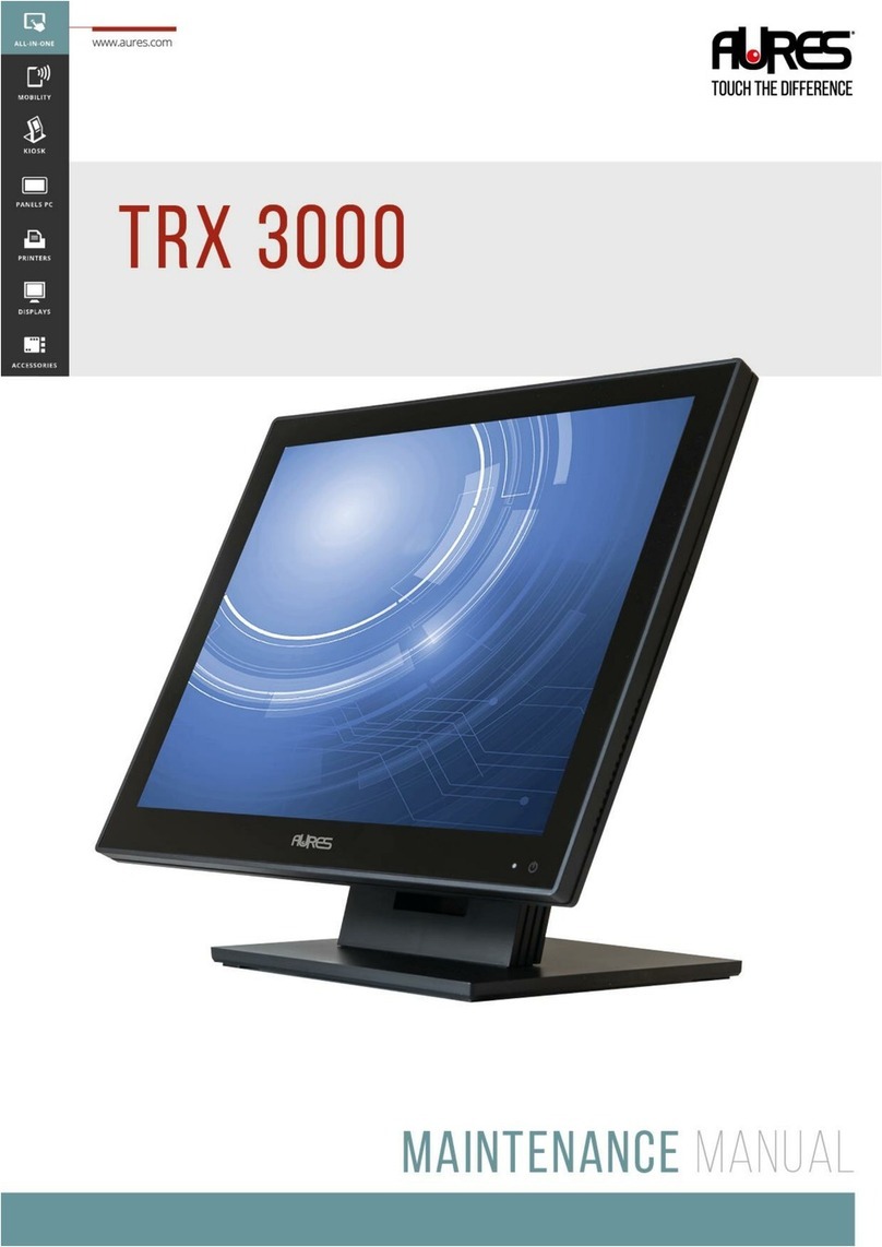
AURES TRX 3000 User manual
AURES
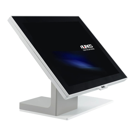
AURES YUNO-151 User manual

AURES
AURES YUNO II User manual
