TOBIAS GRAU CX42-0 User manual

XT-A FLOOR / TABLE LED OSA CX42-0
CX42-1
CX42-2
CX42-3
CX42-4
CX42-5
CX42-6
CX42-7
CX42-8
CX42-9
CC42-0
CC42-1
CC42-2
CC42-3
CC42-4
CC42-5
CC42-6
CC42-7
CC42-8
CC42-9
GX42-0
GX42-1
GX42-2
GX42-3
GX42-4
GX42-5
GX42-6
GX42-7
GX42-8
GX42-9
GX43-0
GX43-1
GX43-2
GX43-3
GX43-4
GX43-5
GX43-7
GX43-8
GX43-9
GX20-5
CH20-5
CH42-0
CH42-1
CH42-2
CH42-3
CH42-4
CH42-5
CH42-6
CH42-7
CH42-8
CH42-9
CH43-0
CH43-1
CH43-2
CH43-3
CH43-4
CH43-5
CH43-7
CH43-8
CH43-9

Leuchtenzusammenstellung
Nr. Leuchte Kopf Schaft Fuß
GX42-0 XT-A FLOOR LED OSA satin/black BR 06 989 BR 06 935 BR 06 610
GX42-1 XT-A FLOOR LED OSA black BR 06 990 BR 06 936 BR 06 640
GX42-2 XT-A FLOOR LED OSA white/black BR 06 579 BR 06 973 BR 06 630
GX42-3 XT-A FLOOR LED OSA satin/white BR 06 578 BR 06 1290 BR 06 620
GX42-4 XT-A FLOOR LED OSA white BR 06 991 BR 06 1291 BR 06 630
GX42-5 XT-A FLOOR LED OSA chrome/black BR 06 990 BR 06 1062 BR 06 640
GX42-6 XT-A FLOOR LED OSA chrome/satin BR 06 989 BR 06 1062 BR 06 640
GX42-7 XT-A FLOOR LED OSA chrome/white BR 06 991 BR 06 1333 BR 06 630
GX42-8 XT-A FLOOR LED OSA raw/black BR 06 1427 BR 06 1429 BR 06 640
GX42-7 XT-A FLOOR LED OSA titan/black BR 06 1428 BR 06 1511 BR 06 640
GX43-0 XT-A TABLE LED OSA satin/black BR 06 989 BR 06 937
GX43-1 XT-A TABLE LED OSA black BR 06 990 BR 06 938
GX43-2 XT-A TABLE LED OSA white/black BR 06 579 BR 06 912
GX43-3 XT-A TABLE LED OSA satin/white BR 06 578 BR 06 1292
GX43-4 XT-A TABLE LED OSA white BR 06 991 BR 06 1293
GX43-5 XT-A TABLE LED OSA chrome/black BR 06 990 BR 06 1060
GX43-7 XT-A TABLE LED OSA chrome/white BR 06 991 BR 06 1335
GX43-8 XT-A TABLE LED OSA raw/black BR 06 1427 BR 06 1431
GX43-9 XT-A TABLE LED OSA titan/black BR 06 1428 BR 06 1512
GX20-5 XT-A TABLE LED OSA USM BR 06 990 BR 06 1061
CH20-5 XT-A TABLE LES OSA USM BR 06 990 BR 06 1337
CH42-0 XT-A FLOOR LED OSA satin/black BR 06 989 BR 06 1063 BR 06 610
CH42-1 XT-A FLOOR LED OSA black BR 06 990 BR 06 1064 BR 06 640
CH42-2 XT-A FLOOR LED OSA white/black BR 06 579 BR 06 1065 BR 06 630
CH42-3 XT-A FLOOR LED OSA satin/white BR 06 578 BR 06 1294 BR 06 620
CH42-4 XT-A FLOOR LED OSA white BR 06 991 BR 06 1295 BR 06 630
CH42-5 XT-A FLOOR LED OSA chrome/black BR 06 990 BR 06 1066 BR 06 640
CH42-6 XT-A FLOOR LED OSA chrome/satin BR 06 989 BR 06 1066 BR 06 640
CH42-7 XT-A FLOOR LED OSA chrome/white BR 06 991 BR 06 1332 BR 06 630
CH42-8 XT-A FLOOR LED OSA raw/black BR 06 1427 BR 06 11435 BR 06 640
CH42-9 XT-A FLOOR LED OSA titan/black BR 06 1428 BR 06 1538 BR 06 640
* CH mit schweizer Stecker
2

Leuchtenzusammenstellung
Nr. Leuchte Kopf Schaft Fuß
CH43-0 XT-A TABLE LED OSA satin/black BR 06 989 BR 06 1269
CH43-1 XT-A TABLE LED OSA black BR 06 990 BR 06 1270
CH43-2 XT-A TABLE LED OSA white/black BR 06 579 BR 06 1271
CH43-3 XT-A TABLE LED OSA satin/white BR 06 578 BR 06 1296
CH43-4 XT-A TABLE LED OSA white BR 06 991 BR 06 1297
CH43-5 XT-A TABLE LED OSA chrome/black BR 06 990 BR 06 1272
CH43-7 XT-A TABLE LED OSA chrome/white BR 06 991 BR 06 1336
CH43-8 XT-A TABLE LED OSA raw/black BR 06 1427 BR 06 1439
CH43-9 XT-A TABLE LED OSA titan/black BR 06 1428 BR 06 1540
* CH mit schweizer Stecker
CX42-0 XT-A FLOOR LED OSA satin/black BR 06 989 BR 06 1229 BR 14 1004
CX42-1 XT-A FLOOR LED OSA black BR 06 990 BR 06 1230 BR 14 1012
CX42-2 XT-A FLOOR LED OSA white/black BR 06 579 BR 06 1231 BR 14 1011
CX42-3 XT-A FLOOR LED OSA satin/white BR 06 578 BR 06 1228 BR 14 1004
CX42-4 XT-A FLOOR LED OSA white BR 06 991 BR 06 1227 BR 14 1011
CX42-5 XT-A FLOOR LED OSA chrome/black BR 06 990 BR 06 1232 BR 14 1012
CX42-6 XT-A FLOOR LED OSA chrome/satin BR 06 989 BR 06 1232 BR 14 1012
CX42-7 XT-A FLOOR LED OSA chrome/white BR 06 991 BR 06 1233 BR 14 1011
CX42-8 XT-A FLOOR LED OSA raw/black BR 06 1427 BR 06 1513 BR 14 1012
CX42-9 XT-A FLOOR LED OSA titan/black BR 06 1428 BR 06 1510 BR 14 1012
CC42-0 XT-A FLOOR LED OSA satin/black BR 06 989 BR 06 1306 BR 14 1004
CC42-1 XT-A FLOOR LED OSA black BR 06 990 BR 06 1307 BR 14 1012
CC42-2 XT-A FLOOR LED OSA white/black BR 06 579 BR 06 1308 BR 14 1011
CC42-3 XT-A FLOOR LED OSA satin/white BR 06 578 BR 06 1305 BR 14 1004
CC42-4 XT-A FLOOR LED OSA white BR 06 991 BR 06 1304 BR 14 1011
CC42-5 XT-A FLOOR LED OSA chrome/black BR 06 990 BR 06 1309 BR 14 1012
CC42-6 XT-A FLOOR LED OSA chrome/satin BR 06 989 BR 06 1309 BR 14 1012
CC42-7 XT-A FLOOR LED OSA chrome/white BR 06 991 BR 06 1310 BR 14 1011
CC42-8 XT-A FLOOR LED OSA raw/black BR 06 1427 BR 06 1437 BR 14 1012
CC42-9 XT-A FLOOR LED OSA titan/black BR 06 1428 BR 06 1539 BR 14 1012
* CC mit schweizer Stecker
3

x
y
2.
3.
5.
Nut
4.
Scharnier
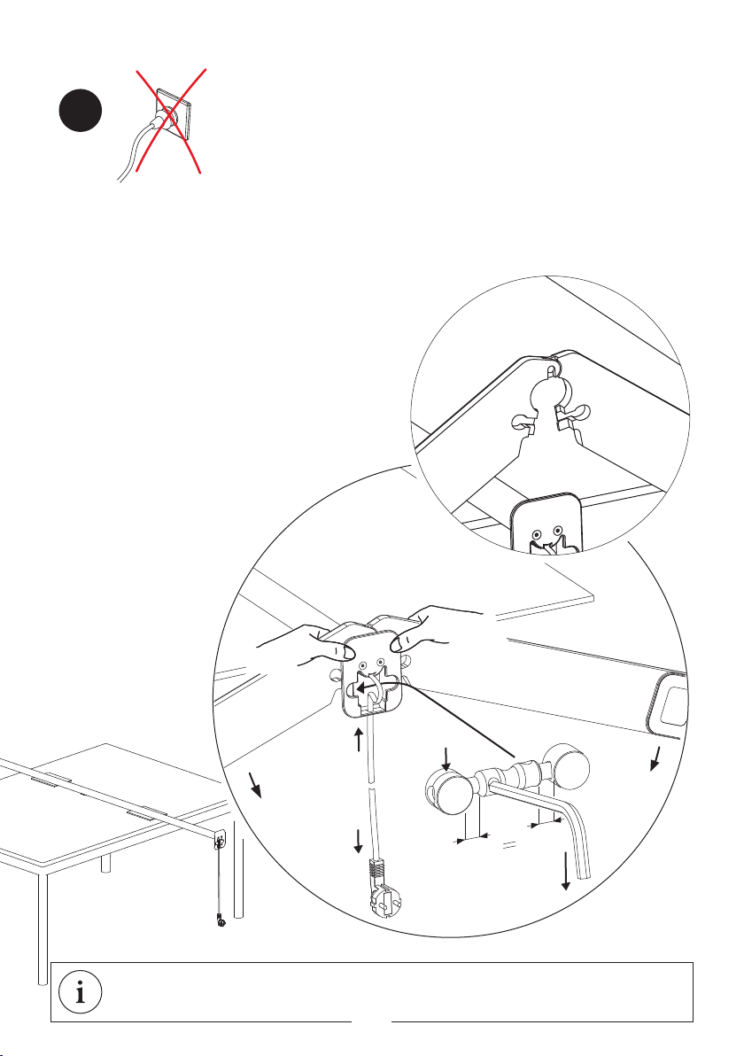
Montage Leuchtenfuss
Legen Sie den Schaft - geschützt gegen Verkratzen - auf eine Tischplatte und montieren Sie in dieser Position
den Fuß und den Leuchtenkopf.
1. Verbinden Sie die beiden Fußteile im Scharnier miteinander.
2. Drücken Sie nun die Fußteile mittels der Daumen direkt an die Kunst-
stoffplatte des Schaftendes (siehe Zeichnung). Die Fußteile bewegen
sich dadurch automatisch in die richtige Position und umschließen
den Leuchtenschaft, ohne ihn zu verkratzen.
3. Das Anschlusskabel in Pfeilrichtung drücken (siehe Zeich-
nung), bis sich eine Schlaufe gebildet hat.
4. Bevor Sie den Spanner einsetzen, muss auf beiden Sei-
ten die gleiche Länge des Gewindes zu sehen sein (x=y), da
sonst das Verspannen von Fuß und Schaft nicht möglich
ist. Spanner richtig herum einsetzen: Drehteil mit Nut nach
links!
5. Nach dem Einsetzen des Spanners das Kabel
nach unten ziehen, damit der Spanner beim
Drehen nicht herausrutscht. Den Span-
ner festziehen. Der Imbusschlüssel
dient dabei als Hebel zum Drehen
der Spannachse. Den Schlüssel
in eines der beiden Löcher ste-
cken und nach unten drücken,
anschließend in das zweite
Loch umsetzen und eben-
falls nach unten drücken.
Dieses Vorgehen solange
wiederholen, bis die Fuß-
teile mit dem Schaft fest
verbunden sind.
01
Der Netzstecker dient der Leuchte als Trennvorrichtung und die
Steckdose muss frei zugänglich sein.
Montage des C-Fußes auf Seite 12
4

Ø 50mm
10-60 mm
Montage Tischadapter
01
Zur Montage des XT-A TABLE Einbauadapters wird ein 50 mm Loch in
einer ausreichend festen Tischplatte benötigt.
Der Netzstecker dient der Leuchte als Trennvorrichtung und die
Steckdose muss frei zugänglich sein.
CH42-6
CH42-7
5

A
1.
2.
3.
4.
Montage Leuchtenkopf
02
1. Ziehen Sie die Stoffhülle nur soweit vom Leuch-
tenkopf ab, wie dies für die Montage des Leuchten-
kopfes an dem Schaft notwendig ist.
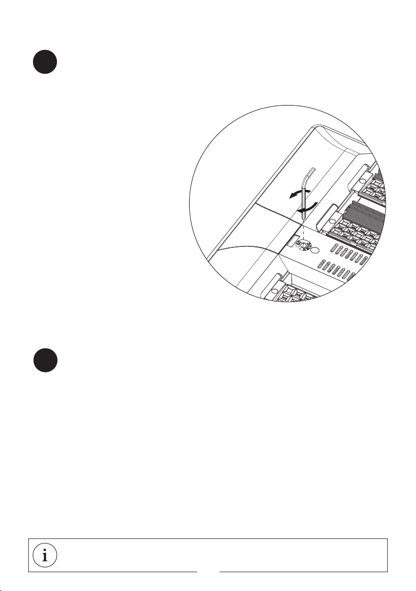
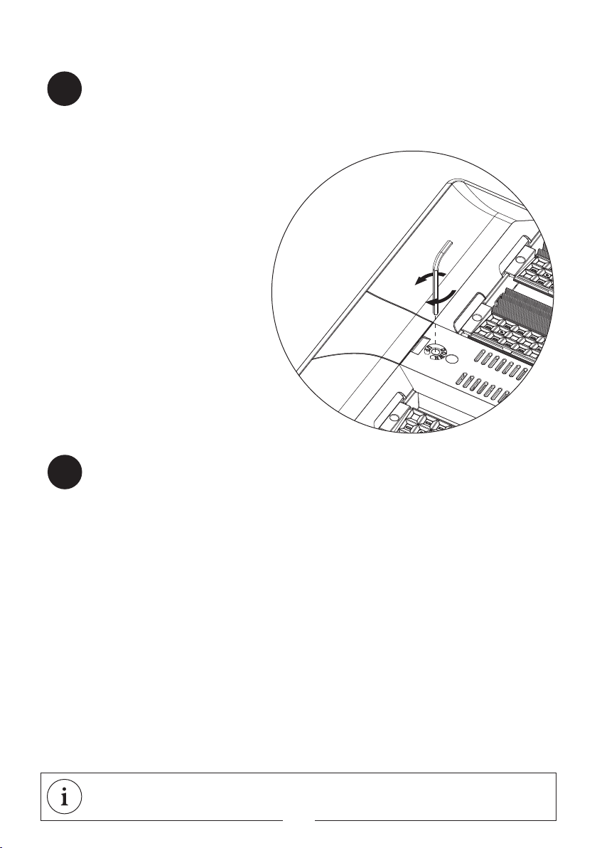
2. Drehen Sie den Stecker vor der Montage des
Leuchtenkopfes in die skizzierte Position (siehe
Zeichnung).
3. Jetzt befestigen Sie den Leuchtenkopf mit
den beiden Schrauben auf dem Schaft. Hierbei
sollten beide Schrauben gleichmäßig fest an-
gezogen werden. Während des Anziehens der
Schrauben sollte der Leuchtenkopf am vorderen
Ende leicht in Pfeilrichtung A gedrückt werden,
damit eine waagerechte Stellung des Leuchten-
kopfes gewährleistet ist. Nun verbinden Sie die
Stecker miteinander.
4. Klappen Sie den Deckel zu.
Der Netzstecker dient der Leuchte als Trennvorrichtung und die
Steckdose muss frei zugänglich sein.
6
Feinjustierung / Inbetriebnahme / Pflegehinweise
Pflegehinweise
Sollte der Leuchtenkopf nach dem Aufstellen der Leuchte nicht
waagerecht stehen, können Sie durch Drehung der Nivellier-
schraube des Leuchtenkopfes seine waagerechte Position
feinjustieren. Bei Drehung in Pfeilrichtung DOWN senkt
sich der Leuchtenkopf, bei Drehung in Pfeilrichtung
UP hebt sich der Leuchtenkopf.
Um den Leuchtenkopf vor Verschmutzung wäh-
rend möglicher Baumaßnahmen oder der End-
reinigung des Gebäudes zu schützen, empfehlen
wir, die Stoffhülle nach der Montage des Leuch-
tenkopfes wieder über den Leuchtenkopf zu
ziehen und zu schließen. Die Leuchte kann trotz
der Stoffhülle bereits betrieben werden.
Stecken Sie den Netzstecker in die Steckdose
(100V-240V; 50-60Hz). Bitte beachten Sie, dass
aufgrund der speziellen Ausführung der Anschluß-
leitung diese im Falle einer Beschädigung nur durch
die Firma Tobias Grau ausgetauscht werden darf.
03
Bitte die Leuchte mit einem trockenen Tuch reinigen, z.B. Microfasertücher für empfindliche Oberflächen.
Bitte keine chemischen Zusätze verwenden. Das Reinigen sollte in abgekühltem Zustand erfolgen. Sollte der
Leuchtenkopf verschmutzt sein (Staub, Fliegen), kann dieser mit einer weichen Staubsaugerbürste gereinigt
werden.
04
7

Funktionsbeschreibung
SENSOR - KONSTANTLICHTREGLER + BEWEGUNGSMELDER
Funktionsbeschreibung:
Der integrierte Konstantlichtregler sorgt dafür, dass die Leuchte sich automatisch der Umgebungshelligkeit
anpasst, d.h. nur soviel Licht liefert, wie tatsächlich benötigt wird. Der ebenfalls integrierte Bewegungs-
melder schaltet die Leuchte anwesenheitsbezogen ein oder aus. Die Helligkeit kann jederzeit individuell
verändert werden, ohne in die Programmierung eingreifen zu müssen. Hierzu bedienen Sie die Leuchte wie
unter DIMMTASTER beschrieben. Die dann „neu“ eingestellte Helligkeit ist temporär und wird nur so lange
gehalten, wie die Leuchte eingeschaltet ist (zur festen Abspeicherung dieses Lichtwertes siehe Anleitung
Fernbedienung)
Weitere Funktionsmerkmale
• Bei genügend Umgebungslicht bleibt die Leuchte trotz Bewegungserkennung ausgeschaltet.
• Bei genügend Umgebungslicht schaltet sich die Leuchte solange aus, bis das eingestellte Beleuchtungsni-
veau unterschritten wird.
• Bei manueller Abschaltung der Leuchte am Taster, bleibt die Leuchte so lange abgeschaltet, bis über einen
Zeitraum von 5 bis 30min. (je nach Einstellung - Werkseinstellung 15min.) keine Bewegung im Erfassungbe-
reich wahrgenommen wird. Erst nach diesem Zeitraum schaltet sich die Leuchte bei erneuter Bewegungser-
kennung automatisch wieder ein.
• Nach Spannungsunterbrechnung bzw. bei geschalteten Steckdosen geht die Leuchte bei erneuter Span-
nungszufuhr auch dann an, wenn sich niemand im Erfassungbereich aufhält und die Leuchte zuvor ausge-
schaltet gewesen ist.
• Beim Einschalten der Leuchte geht diese immer auf den eingestellten Helligkeitswert an.
DIMMTASTER
1 x Taster kurz drücken - Leuchte geht an
Taster gedrückt halten - Leuchte wird heller
Taster nochmal gedrückt halten - Leuchte wird dunkler
1 x Taster kurz drücken - Leuchte geht aus
01
02
8

Funktionsbeschreibung
ca. 4m
ca. 6m
04
Erfassungsbereich des Bewegungsmelders:
9

PRI: AC 120-240V / 50-60 Hz / SEC: max. 58V max. 0,88A / 98W LED
Diese Leuchte enthält eingebaute LEDs. Die LEDs in dieser Leuchte können nur vom Hersteller
ausgetauscht werden. A-A++
A-A++
Montage C-FUß
2x
10

GARANTIE:
Sie haben ein hochwertiges Produkt erworben, welches mit Sorgfalt produziert und verpackt worden ist. Sollten
Sie dennoch einmal Grund zur Beanstandung haben, wenden Sie sich bitte ausschließlich an Ihren Händler.
Geben Sie bitte die auf der letzten Seite genannte Endkontrollnummer bei Ihrer Reklamation an. Ihre
Reklamation wird bei uns im Hause umgehend bearbeitet. Bitte haben Sie Verständnis, dass eine Garantie
unsererseits nur bei sachgemäßer Montage übernommen werden kann - wir empfehlen daher Fachbetriebe.
DEUTSCH
Geprüft und zertifiziert nach europäischer Leuchtennorm EN 60598
Die lichttechnischen Daten sind im Hersteller-neutralen Lichtlabor von DIAL vermessen worden.
EN 12464 Die Leuchte ist nach EN 12464 bildschirmarbeitsplatztauglich
PRI: AC 120-240V / 50-60 Hz / SEC: max. 58V max. 0,88A / 98W LED
Diese Leuchte enthält eingebaute LEDs. Die LEDs in dieser Leuchte können nur vom Hersteller
ausgetauscht werden. A-A++
A-A++
11
2006/95/EG | 2004/108/EG
XT-A FLOOR / XT-A TABLE LED OSA
Die Ware muss vor Montage auf optische Fehler bzw. Kratzer überprüft werden. Mit der Montage
erlischt der Reklamationsanspruch auf optische Mängel der Ware.
x
y
2.
3.
5.
Nut
4.
Scharnier
Mounting the Base
01
Place the shaft of the lumianire on a flat surface - protecting against scratches - and assemble the foot and
the head of the luminaire.
1. Connect both foot sections together by the hinge.
2. With your thumb, press the plastic plate directly onto foot sections
at the bottom of the shaft (see diagram). The foot sections will
automatically move into the correct position, enclosing the shaft
of the lumiaire without scratching it.
3. Push the connectiing cable in the direction of arrow (see
diagram) until a loop is formed.
4. Before inserting the clamps, see that both sides have the
same length of thread (x=y), otherwise it is not possible for
the foot to embrace the shaft. Apply the correct amount of
tension: turn part with groove to the left!
5. After employing the clamp, pull the cable
down so that the clamp does not slip while
rotating. The clamp will tighten. Use an
allen key to rotate the chuck axis.
Insert the key into one of the two
holes and push down. Move onto
the second hole and do the
same. Repeat this porocedu-
re until the foot sections are
securely connected to the
shaft.
The power plug is used as a circuit breaker and the plug socket
must be easily accessible.
Mounting the C-BASE on page 22
12

Ø 50mm
10-60 mm
Mounting the Table Adapter
01
To assemble the XT-A TABLE MONO installation adapters, a 50 mm hole
in a sufficiently solid tabletop is required.
The power plug is used as a circuit breaker and the plug socket
must be easily accessible.
13

A
1.
2.
3.
4.
Mounting th Lamp Head
02
1. Remove the cover.
2. Turn the multi-point connector before mounting
the lamp head as shown in the illustrated position
(see diagram).
3. Attach the lamp head to the shaft with the
two screws. Both screws should be evenly tigh-
tened. While tightening the screws of the lamp
head, the front end should be lightly pushed in
the direction of arrow A so that the lamp head
achieves a horizontal position. Now connect the
multi-point connectors together.
4. Assemble the cover.
The power plug is used as a circuit breaker and the plug socket
must be easily accessible.
14
Fine Adjustment / Setup / Care Instructions
Care Instructions
03
04
Please clean the luminaire with a dry cloth such as a microfiber cloth for sensitive surfaces. Please do not use
chemical additives. The cleaning should take place after the luminaire has cooled down. If the lamp head is
dirty (dust, flies), it can be cleaned with a soft brush vacuum cleaner.
Following set up of the lumianire, if the lamp head is not level, the
horizontal position of the lamp head can be finely adjusted
by turning the levelling screw of the lamp head. Rotating
the levelling screw in the direction of the arrow DOWN
lowers the lamp head, rotating it in the direction of
arrow UP, raises the lamp head.
To protect the lamp head from possible conta-
mination during construction or cleaning of the
building, we recommend that after assembling
the lamp head, pulling the cloth cover over the
lamp head and closing it. The lamp can still be
operated despite the cloth cover.
Plug the power plug into the wall outlet (100V-
240V; 50-60Hz). Please note that due to its
special design, if damaged, the power supply
cable should only be replaced by the company To-
bias Grau.
15

Functional Description
SENSOR – CONSTANT LIGHT CONTROLLER + MOTION SENSOR
Function Description:
The integrated constant light controller ensures that the luminaire adapts automatically to the ambient
brightness, i.e. it only provides as much light as is actually required. The integrated motion sensor switches
the luminaire on or off depending on whether it detects a presence. The brightness can be individually
adjusted
at any time without having to intervene with the programming. In this case, the luminaire is operated
as described under DIMMER SWITCH. The “new” brightness setting is thus temporary and is only maintained
for as long as the luminaire is switched on (to save this light level permanently, see instruction remote
control)
Other Functional Features
• If there is sufficient ambient light, the luminaire remains switched off even if motion is detected.
• If there is sufficient ambient light, the luminaire switches itself off and remains switched off until the light
level drops below the preset intensity.
• If the luminaire is switched off manually using the switch, the luminaire remains switched off as long as no
motion is registered within its detection range for a period from 5 to 30 minutes (depending on setting –
factory setting: 15 minutes). No motion will be detected within the detectable range. Only after this period
has elapsed does the luminaire automatically switches itself on again if motion is detected.
• If the power supply is interrupted, such as in the case of changing power sockets, the luminaire will switch
back on when the power supply is resumed even if nobody is within the detection range and the luminaire
was previously switched off.
• When the luminaire is switched on, it always comes back on at the set brightness level
DIMMER SWITCH
1 x quick press of switch – light goes on
hold switch down – light gets brighter
hold switch down again – light gets darker
1 x quick press of switch – light goes off
01
02
16

Functional Description
03
ca. 4m
ca. 6m
Detection range of the motion sensor
17

PRI: AC 120-240V / 50-60 Hz / SEC: max. 58V max. 0,88A / 98W LED
This luminaire contains built-in LEDs. The LEDs can be replaced by the producer only. A-A++
A-A++
Mounting C-BASE
2x
18

GUARANTEE:
You have purchased a high-quality product that was produced and packaged with the utmost care. Should you
nevertheless have grounds for complaint, please contact your retailer quoting the final inspection number as
stated on the last page of this document. We will deal with your complaint immediately. This warranty applies
only to products that have been fitted appropriately – we therefore recommend fitting by qualified personnel.
ENGLISH
The photometric specifications were measuered by multivendor lighting-laboratory DIAL.
EN 12464 Based on EN 12464 the lamp is suitable for workstations.
PRI: AC 120-240V / 50-60 Hz / SEC: max. 58V max. 0,88A / 98W LED
This luminaire contains built-in LEDs. The LEDs can be replaced by the producer only. A-A++
A-A++
Inspected and certified to european lighting norm EN60598
19
2006/95/EG | 2004/108/EG
XT-A FLOOR / XT-A TABLE LED OSA
The products must be checked for visual defects, and/or scratches, prior to assembly. Once the
product has been assembled, the right for a customer to make a complaint due to visual defects
expires.

BR 16 1500 G/Stand 03/17
Endkontrollnummer 2 Jahre Garantie
5 Jahre Garantie auf die LED
Final inspection number 2 years guarantee
5 years guarantee of LED
Numéro de contrôle final 2 ans de garantie
5 ans de garantie sur les LED
Numero di controllo finale 2 anni di garanzia
5 anni di garanzia per i LED
This manual suits for next models
59
Table of contents
Languages:
Other TOBIAS GRAU Home Lighting manuals

TOBIAS GRAU
TOBIAS GRAU JOSEPHA TABLE User manual

TOBIAS GRAU
TOBIAS GRAU SIXTEEN table LX00-0 User manual

TOBIAS GRAU
TOBIAS GRAU XT-A TABLE PLUS 70/90 USM LED OSA User manual

TOBIAS GRAU
TOBIAS GRAU XT-A FLOOR PLUS 120 User manual

TOBIAS GRAU
TOBIAS GRAU TEAM HOME Clamp TM00-0 User manual

TOBIAS GRAU
TOBIAS GRAU XT-A FLOOR PLUS 70 User manual

TOBIAS GRAU
TOBIAS GRAU FALLING IN LOVE User manual


