manuals.online logo
Brands
  1. Home
  2. •
  3. Brands
  4. •
  5. TOHATSU
  6. •
  7. Outboard Motor
  8. •
  9. TOHATSU MFS 40 User manual

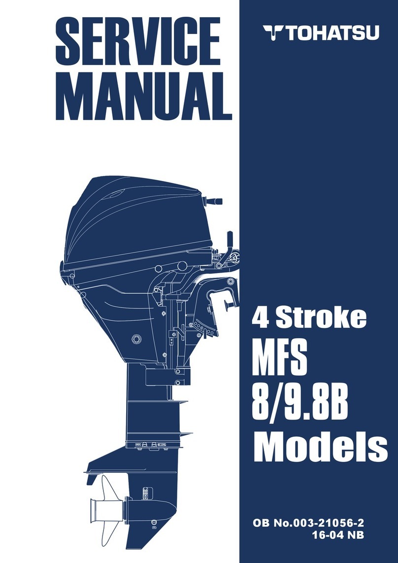
TOHATSU MFS 40 User manual

MFS
40/50A
OB No.003-21067-0
14-09 NB
4st 40/50 2014
ÌÀ`ÕVÌ
ivÀi Ài>`} ÌÃ >Õ>
This service manual provides information that is needed for inspection, service and repair of
applicable outboard motors. For information about operation of the products that are not described
in this document, refer to the owners manual. For our customers' safe and dependable use of the
product for long term, it is essential to maintain the performance and quality of the outboard. To
ensure this, the maintenance and service have to be done properly by service technicians with
fundamental knowledge and skills. This manual is utilized so that our customers can always use their
outboard motor with full satisfaction.
Safety Information
Safety Statements
The following safety statements are found throughout this manual and indicate
information which, if ignored, could result in fatal safety hazards or property damage:
7,  
`V>Ìià Ìi «ÀiÃiVi v > >â>À` À >
ÕÃ>vi >VÌÛÌÞ ÜV] v }Ài`] VÕ`
ÀiÃÕÌ  ÃiÛiÀi ÕÀÞ À `i>Ì°
 ,
`V>Ìià Ìi «ÀiÃiVi v > >â>À` ÜV]
v }Ài`] Ü ÀiÃÕÌ  ÃiÛiÀi ÕÀÞ À
`i>Ì°
1/"
`V>Ìià Ìi «ÀiÃiVi v > >â>À` À >
ÕÃ>vi >VÌÛÌÞ ÜV] v }Ài`] VÕ`
ÀiÃÕÌ  À «iÀÃ> ÕÀÞ À `>>}i Ì
Ìi «À`ÕVÌà À v>VÌið
Attention:
i
4st 40/50 2014

 
"#   

   " ! &!  !
   ""!'
   
 
 $  $# ! ! "# ""' 
 % !%!"  ! ' $"  "!& ! %!"




 !' #  

!- *+)*!&&!+ ,$"-$).,%(# 2 *.--%(# %-
%( -$! $)- 0-!+ )"**+)1%'-!&2   3
  3 ( +!')/! !+%(# 

!+!".& ()- -) .+(
%  ! "#!" # $% !&$   $! 
 ) &$   % & !# % " #    

 
+2#- *'/
'(   
#- .# -+,#((#- &$/



 













 





 




 
 
-,#' +('-!
 )' 

  


 


-.
7 -:+9 8 176  ;@ -5)93:
-=-4 -)9::@  
 
!015    ;  
 
!015     ;  

!015      ;  
")8-9-, 7 4-9 -) 16/  
-=-4 -)9
$):0-9     
978-44-9 !0).; 
 4< +0
 16 
!6)8 
!8916/ 
 !8916/ -;)16-9 
 <:0 7,
 )44  
 :89.55.: "1*/< 8=;270 ;;A 
 !855.: .*:270 
*55 .*:270  
!./
8.;, 2< 87 A!.6*4;
270 
 5 ".*5    
85< 

 89. 5.: ;;A  #@ @ 

 89. 5.: ;;A  #@ @ 
 
 89. 5.: ;;A  #@  @ 

 89. 5.: ;;A  #@  @

 89. 5.: ;;A  9; "#  @  @
 
 89. 5.: ;;A  9; "#  @  @
 
 89. 5.: ;;A  #@  @
 
 89. 5.: ;;A  #@  @ 
 
 89. 5.: ;;A  #@ @
  89. 5.: *:-?*:. 2<
 #1 =;< 85-.: 
"9 2< 27 
 " 899.: 
 %*;1.:  
 89. 5.: =< 9 

-4%/ ,)1
;< 
 .%#)!*1--*0
"5 -. *66.:
;;BA
   
!.68>270 /8 ?*:-  0.*:
+.* 270 8=<.: :*,.
!8 5.: .*:270 <<*,16.7<
 '
!.68>270 8: 7;<*5 70 9:89. 5.:
;1*< 18=; 70 :8 5.: +.* 270
ø28 6xø22xø17xH75 5
-3=;<270 9 7 87  0.*:
1. 01<
"1 66270 *=0.
 &  
$;.- <8 *<<*,1 - *5 0*=0.
?1.7 6.*;=:270 +*,45*;1
2*5*=0. 5*<.
   
!.68>270 8: *<*,1270 927287
 0.*: 7=<
.>.5 .*: =< %.7,1
  
!.68>70 8: *<<*,1 70 927287
 0.*: 7=<
.>.5 .*:=< "8,4.<
  
.>.5 .*:.*: 70 7;<*55 #885
   
7;<*5 70 /8:?*:-  0.*:
+.*:270
.*;=:270 +*,45*;1 +.<?..7 /8 ?*:-
 0.*:*7- 927 87  0.*:
*,45*;1 .*;= 270 #885 <
   
.*;=:270 0*9;
#1 ,47.;; *=0.
   
:>.: !8-
  
!.68>270 8: 7;<*5 70 9:89. 5.:
;1*< 18=; 70 +.* 270
!.68>270 :.>.:;.  0.*:
+.*:270
$7 >.:;*5 = 5.: 5*<.
   
!.68>70 9:89.55.: ;1*/<
18=; 70
:89. 5.: "1*< 8=;270 = 5.: ;;BA
   
.>.5 .*:.*: 70 =55.: ;;BA
   
!.68>270 /8:?*:-  0.*:+.*:70
8=<.: *,.
ø100xø79 5xø51 5xø61 5
.7<.: 5*<.
  
!.68>70 8: 27;<*55270 9:89.55.
;1*/< 18=;270 +.*: 70

 

.*: 70 =<.: :.;; 2<
   
<*,1270 /8:?*:-  0.*:
+.* 270 8=<.: :*,.
.*;= 270 +*,45*;1
*,45*;1 .*;= 270 #885 5*69
   






LÕÌ ÌÃ >Õ>
«ÃÌ >` ÕÃi v ÌÃ >Õ>
This service manual is designed so that service persons are able to perform repairs correctly.
Understand the following matters well for efficient service and repair.
Each chapter begins with the introduction of special tools that are used for the work described.
Parts that are serviced in each chapter and their details are presented by using a component composition
diagram.
Fastening torques are described in the component composition diagram. In the body text are critical
points of the applicable work.
Pictograms indicate that there is an important work instruction for the relevant parts. It also shows the type
of lubricant and its application point(s).
The component composition diagrams describe the names of the parts, the number of pieces of the parts
used, size of fasteners and special notes.
Specific works are described in detail by using illustrations and adding advice on the work.
ii
4st 40/50 2014
%XAMPLE 0RESSURE
#ONVENTIONAL SYSTEM KILOGRAM METER UNIT
#ONVENTIONAL SYSTEM 53 POUND INCH UNIT
3) UNIT  KGFCM  -0A
 -EASUREMENTS ARE SHOWN USING 3) UNIT FOLLOWED BY CONVENTIONAL UNITS 53 UNIT AND ;*APANESE DOMESTIC UNIT=
 -0A( PSI); KGFCM

=
%XAMPLE  4ORQUE

 4HE CONVENTIONAL UNIT FOR MEASUREMENT OF FORCE USES KGF KILOGRAM FORCE TO DISCRIMINATE IT FROM
KG MASS KILOGRAMOF3) UNIT SYSTEM
 .qM(LBqFT); KGFqM=
%XAMPLE  6OLUME
 CM

( FLOZ)
%XAMPLE  ,ENGTH
 MM( IN)
This manual uses SI unit system (International System of Units) for pressure, force (load), torque and
stress. This manual newly adopts the international unit construction system (SI unit system) followed by the
conventional imperial and metric systems enclosed by ( ) and [ ] as described below.
<Reference>
What is the SI unit system?
Although the measurement unit is standardized mostly with metric system in the world, the metric system
includes different kinds of unit systems.
Though the metric system was established expecting that a single unit system would be used in the world,
various physical units were established later, resulting in branching the metric system in different unit
systems.
The new unit system is called "International System of Units" because it was established for the purpose of
unifying the different unit systems.
Since the metric system was initially established in France, and International Bureau of Weights and
Measures (IBWM) is located in Paris, General Conference of Weights and Measures (GCWM) passed a
resolution of the international unit system as "Systéme International d'Unités (French)" that is abbreviated as
"SI unit".
For example, conventional metric system uses the unit of mass (kg) and unit of force (kg or kgf) without
discriminating them, but the SI unit system uses, for example, "kg" as the unit of mass, and "N" as the unit of
force, aiming to apply a kind of unit for a kind of physical quantity.
iii
4st 40/50 2014
iÃVÀ«Ì v *VÌ}À>«
3PECIFIED
%LECTRICAL
6ALUE
,UBRICATION
/IL
3PECIAL 4OOL
3PECIFIED
-EASUREMENT
6ALUE
4IGHTENING
4ORQUE
3PECIFIED 0ART
4EST 2UN
!DJUSTMENT
%NGINE 20-
5SE ,IMIT
"
,*
"

4HE FOLLOWING SYMBOLS REPRESENT THE CONTENTS OF INDIVIDUAL CHAPTERS
4HE FOLLOWING SYMBOLS INDICATE ITEMS NEEDED FOR THE SERVICE
4HE FOLLOWING SYMBOLS INDICATE A POINT TO WHICH LUBRICATION OIL SEALING AGENT OR SCREWLOCKING AGENT IS TO BE APPLIED
{ÃÌ
"
ÀÉ
"
'%!2
'%!2
/
/
"
,-
"
/
,-
/
,-
""*°
-"
-"£Ç
£Ç
" 


 

/


/
/
 

/


/
"
"
/


)NSPECTIONS AND
!DJUSTMENTS
3ERVICE
)NFORMATION 3ERVICE $ATA
&UEL 3YSTEM
&UEL )NJECTION
,OWER 5NIT %LECTRICAL
3YSTEM
0OWER 5NIT
4ROUBLESHOOTING
2IGGING 7IRING
$IAGRAMS
"RACKET
 STROKE
ENGINE OIL 'EAR OIL
!4& $%82/. III
/"- 'REASE
4EFLON¤ 'REASE
4%&,/.
,OW
4EMPERATURE
,ITHIUM 'REASE
,)4()5-
/IL #OMPOUND
;
3HIETSU 3ILICON
=
3/#
;+ONISHI "OND=
s
'
)NSTANT !DHESIVE
;4HREE "OND¤=
s  
3CREW ,OCKING
!GENT
;,OCTITE¤=
s
 
3EALANT
;,OCTITE¤=
s

3CREW ,OCKING
!GENT
;,OCTITE¤=
s

3CREW ,OCKING
!GENT
;4HREE "OND¤=
s

3CREW ,OCKING
!GENT
;4HREE "OND¤=
s
"
3CREW ,OCKING
!GENT
;4HREE "OND¤=
s

iv
4st 40/50 2014
£°-iÀÛVi vÀ>Ì
£
`iÌvV>Ì
}i -iÀ> ÕLiÀ®
……………… 1-2
Ó-iVÕÀ} v ÜÀ Ã>viÌÞ …… 1-2
1) Fire Prevention …………………… 1-2
2) Ventilation ………………………… 1-2
3) Protection ………………………… 1-2
4) Genuine Parts……………………… 1-2
5) Tools………………………………… 1-3
6) Recommendations on service …… 1-3
7) Cautions in disassembling and
assembling components ………… 1-4
ΰ /à >` ÃÌÀÕiÌà ……… 1-5
1) Test Propeller ……………………… 1-5
2) Measuring instruments …………… 1-5
3) Special Tools ……………………… 1-6
{° *Ài`iÛiÀÞ ëiVÌ ……… 1-9
1) Steering Handle …………………… 1-9
2) Gear Shift ………………………… 1-9
3) Engine Oil ………………………… 1-9
4) Gear Oil …………………………… 1-9
5) Fuel Line …………………………… 1-10
6) Rigging……………………………… 1-10
7) Inspection of PTT unit …………… 1-10
8) Inspection of gas shock absorber 1-10
9) Inspection of starting switch and
stop switch ………………………… 1-11
10) Cooling water check port ………… 1-12
11) Idling………………………………… 1-12
12) Propeller Selection………………… 1-12
13) Trim Tab …………………………… 1-13
x° Ài> "«iÀ>Ì …………… 1-13
Ȱ /iÃÌ ,Õ …………………………… 1-14
ǰ iVà vÌiÀ /iÃÌ ,Õ ……… 1-14
Ó°-iÀÛVi >Ì>
£ "ÕÌi iÃÃ …………… 2-2
1) Engine Dimensions ……………… 2-2
2) Transom Bolts …………………… 2-4
ÓÕi iVÌ -ÞÃÌi ……… 2-5
1) ECU Fuel Feed System ………… 2-5
Î
}i ÕLÀV>Ì -ÞÃÌi >}À>
2-6
{
} 7>ÌiÀ -ÞÃÌi >}À>
2-7
x-«iVvV>ÌÃ …………………… 2-8
È>Ìi>Vi >Ì> ……………… 2-12
Ç /}Ìi} /ÀµÕi >Ì> …… 2-20
n
-i>>Ì ««V>Ì V>ÌÃ
2-22
ΰ>Ìi>Vi
£° -«iV> /Ã ……………………… 3-2
Ó° ëiVÌ -Vi`Õi ………… 3-3
ΰ ëiVÌ Ìià ……………… 3-4
1) Inspection of Top Cowl …………… 3-4
2) Inspection of Fuel System Piping 3-4
3) Inspection of Fuel Tank…………… 3-5
4) Inspection of Fuel Filter…………… 3-5
5) Replacement of Engine Oil ……… 3-6
6) Engine oil replacement indicator function
reset method ……………………… 3-7
7) Replacement of Oil Filter ………… 3-8
8) Inspection of Gear Oil Quantity … 3-9
9) Inspection of Water Pump ……… 3-9
10) Replacement of Gear Oil ………… 3-11
11)
Inspection of Gear Case
(for leakage) …………………………
3-
12
12) Inspection of timing belt ………… 3-13
13) Replacement of timing belt ……… 3-13
14) Inspection of Spark Plugs………… 3-17
15) Inspection of Compression Pressure
……………………………………… 3-18
16) Inspection and Adjustment of
Valve Clearance
……………………………
3-
19
17) Adjustment of shift • throttle cable
……………………………………… 3-20
18)
Inspection of Shift Lever Gear Operations
………………………………………………
3-
22
19) Inspection of PTT Unit Operation
……………………………………… 3-23
20)
Inspection of Gas Assistant Unit Operations
…………………………………………………
3-
24
21) Inspection of PTT Fluid Quantity… 3-24
22)
Inspection of Idle Speed………………
3-
25
23) Inspection of Ignition Timing …… 3-25
24) Inspection of Anodes……………… 3-26
25) Replacement of Anodes ………… 3-27
26) Inspection of Propeller …………… 3-27
27) Inspection of Thermostat ………… 3-27
28)
Inspection of Cooling Water Passage
…………………………………………
3-
28
29)
Inspection of Cooling Water Pressure
…………………………………………
3 -
28
30) Flushing with Water ……………… 3-29
31) Inspection of Battery ……………… 3-30
32) Greasing points …………………… 3-31
{°
Õi -ÞÃÌi Õi iVÌ®
£° -«iV> /Ã ……………………… 4-2
Ó° *«} ÀÀ>}iiÌ >}À> 4-3
Fuel Hose, Vent Hose, Breather Hose,
Cooling Water Hose…………………………
4-3
ΰ *>ÀÌà >ÞÕÌ ……………………… 4-4
Intake Manufold ………………………… 4-4
Fuel System …………………………… 4-6
Electric Parts …………………………… 4-8
Separate Fuel Tank …………………… 4-10
{° 1 -ÞÃÌi………………………… 4-11
£® v}ÕÀ>Ì v 1 -ÞÃÌi
……………………………………… 4-12
1) Sensors …………………………… 4-12
2) Actuators…………………………… 4-14
3) Control System (ECU) …………… 4-15
Ó® ÌÀ -ÞÃÌi ……………… 4-16
ή Õi iVÌ ÌÀ …… 4-17
1) Fuel Injection Timing ……………… 4-16
2) Starting Fuel Increase Correction
……………………………………… 4-17
3) Acceleration Fuel Increase Correction
……………………………………… 4-17
4) Deceleration Fuel Decrease Correction
……………………………………… 4-17
5) Correction Based On
Intake Air Temperature …………… 4-17
6) Correction Based On
Cylinder Cooling Water Temperature
……………………………………… 4-17
{®
ÌÀ v Õi ii` *Õ« *®
……………………………………… 4-18
x® ÌÀ v />ViÌiÀ …… 4-18
È®
7>À} ÕââiÀ >` >« ®] >`
ÌÀ v }i ,iÛÕÌ -«ii`
……………………………………… 4-19
v
4st 40/50 2014
1) Locations of warning buzzer
and lamp (LED) …………………… 4-17
2) Warning notification, abnormality
and action to be taken …………… 4-18
x° }Ì -ÞÃÌi ………………… 4-19
1) Ignition Timing Controls ………… 4-20
2) Ignition and Combustion Orders … 4-20
3) Ignition Timing …………………… 4-20
4) Operations ………………………… 4-20
Ȱ
«iÌÃ v Õi ii` -ÞÃÌi
4-22
1) Fuel Pump (Low Pressure
Mechanical Pump) ………………… 4-22
2) Vapor Separator…………………… 4-22
3) Fuel Regulator …………………… 4-23
4) Fuel Cooler ………………………… 4-23
ǰ
"ÕÌi v Õi iVÌ -ÞÃÌi
……………………………………… 4-24
1) Air Intake System ………………… 4-24
n° ëiVÌ Ìià ……………… 4-25
1)
Inspection of Fuel Supply System Piping …
4-25
2) Inspection of Filter ………………… 4-25
3) Inspection of Fuel Pump ………… 4-27
4) Inspection of Fuel Connector …… 4-27
5) Measuring fuel pressure ………… 4-28
6) Inspection of Fuel Regulator …… 4-29
7) Draining Fuel ……………………… 4-30
8) Disassembly of Vapor Separator… 4-30
9) Inspection of Vapor Separator…… 4-31
10) Reassembly of Vapor Separator … 4-32
11)
Inspection of ISC (Idle Speed Control) 4-33
12)
Inspection of Idle Speed……………… 4-33
x°*ÜiÀ 1Ì
£° -«iV> /Ã ……………………… 5-2
Ó° *>ÀÌÃ >ÞÕÌ ……………………… 5-3
Engine …………………………………… 5-3
Magneto ………………………………… 5-4
Electric Parts …………………………… 5-5
Fuel system …………………………… 5-7
Vapor Separator………………………… 5-9
Intake Manifold ………………………… 5-10
Pulley • Timing Belt …………………… 5-12
Cylinder Head & Oil Pump …………… 5-13
Cylinder • Crankcase ………………… 5-15
Piston & Crankshaft …………………… 5-16
Top Cowl ………………………………… 5-17
ΰ ëiVÌ Ìià ……………… 5-18
1) Inspection of Compression Pressure
……………………………………… 5-18
2) Inspection of Oil Pressure ……… 5-18
3) Inspection of Valve Clearance…… 5-18
4) Removing Power Unit …………… 5-18
5) Removing Timing Belt and Pulley
……………………………………… 5-22
6) Inspection of Timing Belt ………… 5-22
7) Installation of Pulley and Timing Belt
……………………………………… 5-23
8) Removing Cylinder Head ………… 5-24
9) Inspection of Valve Spring ……… 5-27
10) Inspection of Valve………………… 5-28
11) Inspection of Valve Guide………… 5-28
12) Inspection of Valve Seat ………… 5-29
13) Correction of Valve Seat ………… 5-30
14) Inspection of RockerArm and
Rocker Arm Shaft ………………… 5-32
15) Inspection of Cam Shaft ………… 5-33
16) Inspection of Cylinder Head……… 5-34
17) Inspection of Oil Pump …………… 5-35
18) Installation of Valves ……………… 5-36
19) Installation of Cam Shaft ………… 5-37
20) Installation of Rocker Arm Shaft … 5-38
21) Installation of Oil Pump…………… 5-38
22) Installation of Cylinder Head …… 5-39
23) Disassembly of Cylinder Block … 5-40
24) Removing of Drive Pulley………… 5-41
25) Installing of Drive Pulley ………… 5-41
26) Inspection of Piston Outer Diameter
……………………………………… 5-42
27) Inspection of Cylinder Inner Diameter
……………………………………… 5-42
28) Inspection of Piston Clearance … 5-42
29) Inspection of Piston Ring
Side Clearance …………………… 5-43
30) Inspection of Piston Rings ……… 5-43
31) Inspection of Piston Pins ………… 5-44
32) Inspection of Connecting Rod
Small End Inner Diameter ……… 5-44
33) Inspection of Connecting Rod
Big End Side Clearance ……………… 5-44
34) Inspection of Crankshaft ………… 5-45
35) Inspection of Crank Pin (rod journal)
Oil Clearance ……………………… 5-46
36) Inspection of Crank Shaft Main Journal
Oil Clearance ……………………… 5-47
37) Selecting of Cylinder/Crankcase
Metal Bearing ……………………… 5-48
38) Selecting of Connecting Rod
Metal Bearing ……………………… 5-49
39) Assembling Piston and Connecting Rod
……………………………………… 5-50
40) Installation of Power Unit ………… 5 -54
ȰÜiÀ 1Ì
£° -«iV> ÌÃ ……………………… 6-2
Ó° *>ÀÌÃ >ÞÕÌ ……………………… 6-4
Gear Case (Drive Shaft) ……………… 6-4
Gear Case (Propeller Shaft) ………… 6-6
ΰ ëiVÌ Ìià ……………… 6-7
1) Draining Gear Oil ………………… 6-7
2) Removing Propeller ……………… 6-7
3) Removing Lower Unit …………… 6-8
4) Disassembly of Cam Rod………… 6-9
5) Inspection of Clutch Cam ………… 6-9
6) Assembly of Clutch Cam Parts … 6-10
7) Removing Water Pump…………… 6-11
8) Inspection of Water Pump ……… 6-12
9) Inspection of Water Pipe ………… 6-12
10)
Disassembly of Water Pump Case (Lower)
……………………………………… 6-13
11) Assembly of Water Pump Case (Lower)
……………………………………… 6-13
12)
Removing Propeller Shaft Housing Ass’y
… 6-14
13)
Disassembly of Propeller Shaft Housing Ass’y
……………………………………… 6-15
14) Inspection of Propeller Shaft Housing
……………………………………… 6-16
15) Assembly of Propeller Shaft Housing
……………………………………… 6-17
16) Disassembly of Propeller ShaftAss’y
……………………………………… 6-19
17) Inspection of Propeller Shaft Ass’y
……………………………………… 6-20
18) Assembly of Propeller Shaft Ass’y
……………………………………… 6-21
vi
4st 40/50 2014
19) Removing Drive Shaft Ass’y……… 6-22
20)
Disassembly of Drive Shaft Ass’y
…… 6-23
21) Inspection of Drive Shaft ………… 6-23
22) Inspection of Pinion (B) Gear …… 6-23
23) Assembly of Drive Shaft Parts…… 6-24
24) Removing Forward (A) Gear Ass’y
……………………………………… 6-25
25) Disassembly of Forward Gear (A) Gear
……………………………………… 6-25
26) Inspection of Forward (A) Gear … 6-26
27) Assembly of Forward (A) Gear Parts
……………………………………… 6-26
28) Disassembly of Gear Case ……… 6-27
29) Inspection of Gear Case ………… 6-28
30)
Inspection of Gear Case (for leakage)
…………………………………………
6-
28
31) Assembly of Gear Case Parts …… 6-29
32)
Measurement of Pinion (B) Gear Height and
Shim Selection
……………………… 6-31
32)
Measurement of Back Lash between Forward (A)
and Pinion (B) Gears and Shim Selection
… 6-32
34) Assembly of Lower Unit Parts …… 6-35
35) Assembly of Pump Case ………… 6-36
36) Attaching Clutch Cam Ass’y……… 6-37
37)
Installing Propeller Shaft Housing Ass'y
…………………………………………
6-
38
38) Measurement of Propeller Shaft Play and
Selection of Washer Thickness … 6-38
39) Installation of Lower Unit ………… 6-39
ǰÀ>ViÌ
£°
*// 7À} >` >ÞÕÌ >}À>
……………………………………… 7-2
Ó° "«iÀ>Ì v *ÜiÀ /Ì……… 7-3
ΰ
"«iÀ>ÌÃ v Þ`À>ÕV ÀVÕÌ
……………………………………… 7-3
Manual Tilt Operation ………………… 7-3
Tilt up Operation ……………………… 7-4
Tilt down/Trim in………………………… 7-5
Shock Absorber Valve ………………… 7-6
Thermal Valve ………………………… 7-7
{° *>ÀÌÃ >ÞÕÌ ……………………… 7-8
Drive Shaft Housing …………………… 7-8
Bracket ………………………………… 7-10
Power Trim & Tilt ……………………… 7-13
Tiller Handle …………………………… 7-14
Bottom Cowl …………………………… 7-16
Shift • Throttle…………………………… 7-18
x° ëiVÌ Ìià ……………… 7-20
1) Inspection of Throttle Cable……… 7-20
2) Friction Lever adjustment and operation
……………………………………… 7-20
3) Removing Drive Shaft Housing … 7-20
4) Pulling Out Upper Mount ………… 7-22
5) Disassembly of Drive Shaft Housing
……………………………………… 7-22
6) Inspection of Oil Strainer ………… 7-23
7) Assembly of Drive Shaft Housing
……………………………………… 7-23
8) Installation of Drive Shaft Housing Ass'y
……………………………………… 7-24
9) Removing Steering Shaft ………… 7-25
10) Installing Steering Shaft ………… 7-25
11) Removing Clamp Bracket
(PTT or GasAssistant Model) …… 7-26
12) Installation of Clamp Bracket
(PTT or GasAssistant Model) …… 7-27
13)
Removing PTT Unit/Gas ShockAbsorber
……………………………………… 7-27
14) Removing PTT Motor …………… 7-28
15) Disassembling PTT Motor ……… 7-29
16) Inspection of PTT Motor ………… 7-30
17) Assembling PTT Motor Parts …… 7-31
18) Removing PTT Pump and Valves 7-31
19) Inspection of PTT Pump and Valves
……………………………………… 7-32
20) Removing Oil Reservoir Tank …… 7-32
21) Inspection of Tilt Cylinder and
Oil Reservoir Tank ………………… 7-33
22) Installation of Reserve Tank……… 7-33
23) Installation of PTT Pump and Motor
……………………………………… 7-34
24) Air-Purging PTT Unit
(separated from outboard motor)
…… 7-35
25) Installation of PTT Unit/
Gas Shock Absorber ……………… 7-36
26) Air-Purging PTT Unit
(installed on the outboard motor)
……………………………………… 7-37
27) Inspection of PTT Solenoid ……… 7-38
28) Inspection of PTT Switch ………… 7-39
n°iVÌÀV> -ÞÃÌi
£° -«iV> /Ã ……………………… 8-2
Ó° iVÌÀV> «iÌ >ÞÕÌ
……………………………………… 8-3
Port Side View ………………………… 8-3
Bow Side View ………………………… 8-4
Starboard Side View …………………… 8-5
Top View ………………………………… 8-6
Bottom Cowl …………………………… 8-7
ΰ *>ÀÌà >ÞÕÌ ……………………… 8-8
Magneto ………………………………… 8-8
Electric Parts …………………………… 8-10
Electric Parts (Starter Motor) ………… 8-12
Intake Manifold ………………………… 8-14
Fuel system …………………………… 8-16
{° }Ì -ÞÃÌi]
}Ì ÌÀ -ÞÃÌi ……… 8-18
1) Inspection of Ignition Sparks …… 8-18
2) Inspection of Plug Cap …………… 8-18
3) Inspection of Ignition Coils ……… 8-19
4) Inspection of Alternator …………… 8-19
5) Inspection of Crank Position
Sensor (CPS) ……………………… 8-20
6) Adjustment of Crank Position
Sensor (CPS) Air Gap …………… 8-20
7) Inspection of Oil Pressure Switch
……………………………………… 8-21
8) Inspection of engine Temperature Sensor
……………………………………… 8-22
9) Inspection of Neutral Switch …… 8-22
10) Inspection of Main (key) Switch … 8-23
11) Inspection of Stop Switch………… 8-23
x° Õi ÌÀ -ÞÃÌi ………… 8-24
1) Inspection of Injectors …………… 8-24
2) Inspection of ISC Valve…………… 8-24
3) Inspection of T-MAT Sensor……… 8-24
Inspection of MAT Sensor ……… 8-24
Inspection of MAP Sensor ……… 8-25
4) Inspection of Fuel Feed Pump (FFP)
.……………………………………… 8-25
5)Inspection of Throttle Position
Sensor (TPS).…………………………… 8-25 vii
4st 40/50 2014
Ȱ -Ì>ÀÌ} -ÞÃÌi ………………… 8-26
1) Inspection of Fuse ………………… 8-26
2) Inspection of Starter Solenoid …… 8-26
3) Disassembly of Starter Motor …… 8-27
2) Inspection of Armature …………… 8-30
5) Inspection of Brushes …………… 8-31
6) Inspection of Starter Motor Pinion
……………………………………… 8-31
7) Inspection of Magneto Switch …… 8-31
8) Assembly of Starter Motor ……… 8-32
ǰ >ÌÌiÀÞ >À}} -ÞÃÌi … 8-34
1) Inspection of Rectifier …………… 8-34
n° 1 Õ«iÀ ……………………… 8-35
°/ÀÕLiÃÌ}
£° /ÀÕLiÃÌ} ÃÌ ………… 9-2
*ÜiÀ 1Ì ………………………… 9-13
State 1 : Engine will not start or
is a little hard to start. ………………… 9-13
Starting System ………………………… 9-13
Ignition System ………………………… 9-15
Fuel System …………………………… 9-17
State 2 : Full throttle engine revolution speed is low.
Engine revolution speed fall off.Engine stalls
………………………………………
9-19
Ignition System ………………………… 9-20
Fuel System …………………………… 9-21
Lubrication System …………………… 9-22
Cooling System ………………………… 9-23
State 3 : Engine rotation is unstable or
hunting occurs in low speed range.
……………………………………… 9-24
Ignition System ………………………… 9-25
Fuel System …………………………… 9-26
*// 1Ì …………………………… 9-27
State 1 : PTT will not operate.
…………
9-27
State 2 : PTT is not capable of sustaining outboard motor.
………………………………………
9-28
>}ÃÃ …………………………… 9-29
£°-iÌ 1«……………………………… 9-29
1) Diagnosis Software Install ……… 9-30
2) Installing USB to serial converter driver
(If there is no RS232 port) ……… 9 -31
Ó° >}ÃÞÃ -vÌÜ>Ài
iVÌ …………………… 9-32
1) Preparation ………………………… 9-32
ΰ "«iÀ>Ì} *ÀVi`ÕÀi ……… 9-33
1) Start Up …………………………… 9-33
2) Models and Menu Selection……… 9-33
3) Preface and Introduction ………… 9-33
4) Setting Communication (COM) Port
……………………………………… 9-34
5) Engine Monitor …………………… 9-36
6) Diagnostic History ………………… 9-37
7) At Engine Shut-down Test ……… 9-38
8) At Engine Running Test ………… 9-39
9) Explanation of Error code………… 9-40
Ó° -iv>}ÃÃ ÕVÌ …… 9-41
1) Terms related to self-diagnosis function
……………………………………… 9-41
2) Operation Procedure of
Self-Diagnosis Function ………… 9-42
3) Warning Indication List ••••
Display for abnormalities
during operation…………………… 9-46
4) Operating Hour Indication List
(Self Diagnosis • Mode 2)………… 9-48
5) Trouble Indication List
(Self Diagnosis • Mode 3)………… 9-50
£ä°,}}}
£° -iÀÛVi vÀ>Ì …………… 10-2
Ó° -iÀÛVi >Ì> ……………………… 10-2
1) Load Limit of Boat ………………… 10-2
2) Installation Dimensions…………… 10-2
3) Clamp Dimensions………………… 10-3
4) Hanging Outboard Motor ………… 10-5
5) Installation of Outboard Motor …… 10-5
ΰ Õi -ÞÃÌi ……………………… 10-6
1) Fuel ………………………………… 10-6
2) Oil…………………………………… 10-6
3) Electric Fuel Pump………………… 10-6
4) Installation of Fuel Filter ………… 10-6
5) Filling Fuel System ……………… 10-7
6) Engine Oil ………………………… 10-7
{°
iVÌÃ Ì "ÕÌL>À` ÌÀ
……………………………………… 10-8
1) Steering Cable …………………… 10-8
2) Drag Link…………………………… 10-9
3) Installation of Remote Control Cable
(Engine Side) ………………………
10-10
x° ÜiÀ 1Ì …………………………
10-13
1) Installation of Propeller ……………
10-13
Ȱ iVÌÀV -ÞÃÌi …………………
10-14
1) Battery Capacity……………………
10-14
2) Connection of Battery Cables ……
10-14
3) Installation of Battery (ies) ………
10-14
ǰ VViÃÃÀià >` iÌiÀà ……
10-15
1) Accessories. ………………………
10-15
2) Installation of Meters………………
10-15
n° "«iÀ>Ì ……………………………
10-17
1) Warning Indication…………………
10-17
££°7À} >}À>
7À} >ÀÌ …………………………… 11-2
-{äÉxä / ÜÌ ÕÌ /iÀ >`i®
iVÌV> ÀVÕÌ ………………………… 11-3
-{äÉxä / ÜÌ ,iÌi ÌÀ®
iVÌV> ÀVÕÌ ………………………… 11-5
-{äÉxä  ÜÌ ÕÌ /iÀ >`i®
iVÌV> ÀVÕÌ ………………………… 11-7
-{äÉxä  ÜÌ ,iÌi ÌÀ®
iVÌV> ÀVÕÌ ………………………… 11-9
 8 ……………………… end of a volume
viii
4st 40/50 2014
£-iÀÛVi vÀ>Ì
Ó-iÀÛVi >Ì>
Î>Ìi>Vi
{
Õi -ÞÃÌi Õi iVÌ®
x*ÜiÀ 1Ì
ÈÜiÀ 1Ì
ÇÀ>ViÌ
niVÌÀV> -ÞÃÌi
/ÀÕLiÃÌ}
£ä VViÃÃÀiÃ
££ 7À} >}À>
 8
"

ÀÉ
ix
4st 40/50 2014
x
£
-iÀÛVi vÀ>Ì

£
`iÌvV>Ì }i -iÀ> ÕLiÀ®
oo 1-2
Ó-iVÕÀ} v ÜÀ Ã>viÌÞ oooo 1-2
1) Fire Prevention …………………………… 1-2
2) Ventilation…………………………………… 1-2
3) Protection …………………………………… 1-2
4) Genuine Parts ……………………………… 1-2
5) Tools ………………………………………… 1-3
6) Recommendations on service …………… 1-3
7) Cautions in disassembling and
assembling components ………………… 1-4
ΰ /à >` ÃÌÀÕiÌà oooo 1-5
1) Test Propeller ……………………………… 1-5
2) Measuring instruments …………………… 1-5
3) Special Tools ……………………………… 1-6
{° *Ài`iÛiÀÞ ëiVÌ oooo 1-9
1) Steering Handle …………………………… 1-9
2) Gear Shift ………………………………… 1-9
3) Engine Oil ………………………………… 1-9
4) Gear Oil …………………………………… 1-9
5) Fuel Line ………………………………… 1-10
6) Rigging …………………………………… 1-10
7) Inspection of PTT unit …………………… 1-10
8) Inspection of gas shock absorber ……… 1-10
9) Inspection of starting switch and
stop switch ……………………………… 1-11
10) Cooling water check port ……………… 1-12
11) Idling ……………………………………… 1-12
12) Propeller Selection ……………………… 1-12
13) Trim Tab…………………………………… 1-13
x° Ài> "«iÀ>Ì oooooo 1-13
Ȱ /iÃÌ ,Õoooooooooooo 1-14
ǰ iVà vÌiÀ /iÃÌ ,Õ oooo 1-14
1-2
-iÀÛVi vÀ>Ì
4st 40/50 2014
£°
`iÌvV>Ì }i -iÀ> ÕLiÀ®
Engine serial number is stamped on the bottom cowl of
outboard motor body.
Ó° -iVÕÀ} v ÜÀ Ã>viÌÞ
£® Ài *ÀiÛiÌ
Gasoline is hazardous material and very flammable. Do not
handle gasoline near ignition source such as spark or static
electricity.
Ó® 6iÌ>Ì
Exhaust gas or gasoline vapor is hazardous for human
health. Be sure to ventilate well when working indoors.
ή *ÀÌiVÌ
Wear a pair of goggles, working gloves and safety shoes to
protect human body from chemicals and oils and eyes from
particles generated by grinding or polishing works. Avoid
adhesion of matters such as oil, grease or sealing agent to
the skin. In case of exposure to such matters, wash away
with soap or warm water immediately.
{® iÕi *>ÀÌÃ
Use parts and/or chemicals that are genuine items or
recommended.
Model Name
Model Type
Serial Number


1-3

4st 40/50 2014
x® /Ã
Use specified special tools to prevent damaging to parts
and to perform work safely and surely. Be sure to follow
installation procedures described in this manual and use
tightening torque specified.
È® ,iVi`>ÌÃ  ÃiÀÛVi
Remove foreign substances and dirt from outboard motor
body and individual parts by cleaning. Apply recommended
oil or grease to rotating areas and sliding surfaces. After
individual works, always perform verifications such as
ensuring smooth movement and sealing.
2 
!#  
1-4
-iÀÛVi vÀ>Ì
4st 40/50 2014
/
,-
/
Ç® >ÕÌÃ  `Ã>ÃÃiL} >`
>ÃÃiL} V«iÌÃ
(1) Secure outboard motor to dedicated stand firmly.
(2) Take special care not to scratch painted surface or mating
surfaces of cylinder and crankcase.
(3) Replace unreusable parts such as packings, gaskets, O
rings, oil seals, spring pins or split pins with new ones after
they were removed . Replace deformed snap rings with new
ones.
(4) When replacing parts, be sure to use genuine parts. For
fluids such as gear oil, use genuine product.
(5) Be sure to use special tools that are specified, and perform
the works properly.
(6) When reassembling parts, use their mating marks. For parts
without mating marks, simple marking makes reassembling
easier. Use applicable parts list for reference.
(7) Clean individual parts that have been removed, and check
their conditions.
(8) When reassembling parts, take sufficient care also for
details such as fits, repair limits, air tight, clogging of oil
holes for lubrication and greasing, packings, wirings and
piping. For components using many bolts and nuts for
assembling, such as cylinder head and crankcase, tighten
all the fasteners evenly to their specified torques clockwise
in two or three stages, inner ones first and then outer ones.
(Reverse the order when disassembling.)
(9) When installing bearings, face the flat (numbered) side to
the special assembling tool.
(10) When installing oil seals, be careful not to scratch the
surface of the lip that contacts with the shaft, and install
them in correct orientation. Apply recommended grease to
the lip before installation.
(11) When applying liquid packing, take sufficient care for the
thickness and quantity. Excessive application may be oozed
out, adversely affecting interior of the crankcase. Use
adhesive after thoroughly reading the instructions.
(12) When servicing power unit, use of wooden work board
makes the work easier.
48 52
52
43
43
41
42
38 37
39
49
539
35
3433
16
89
10
13
4
7
8109
12
12
12
44
45
ig 5-12
43
5
{ÃÌ "
{ÃÌ
"
/
,
/
/

ÓÈÎ
ÓÇ£®


      
   
1-5

4st 40/50 2014
Ó® i>ÃÕÀ} ÃÌÀÕiÌÃ
For the following measuring instruments, use commercially available ones.
Circuit tester ( Resistance : 1Ω, 10Ω, 10 kΩ,AC voltage : 30 to 300V, DC voltage : 30V )
Vernier calipers ( M1 type, 300 mm )
Micrometer ( minimum graduation of 0.01, outer, 0 to 25 mm, 25 to 50 mm, 50 to 75 mm )
Cylinder gauge ( 4 to 6 mm, 10 to 25 mm, 25 to 30 mm, 50 to 75 mm )
Ring gauge ( ø5.5, ø17, ø42, ø70 )
Dial gauge ( minimum graduation of 0.01 )
Thickness gauge ( 0.03 to 0.3 mm )
V block
Surface plate ( 500 mm x 500 mm )
Dial gauge magnet base or dial gauge stand
ΰ /à >` ÃÌÀÕiÌÃ
£® /iÃÌ *À«iiÀ
P/N. 3KY-64110-0
Outer diameter : 236 mm
With : 21 mm
Outboard motor model Rotational speed at WOT
(Wide Open Throttle) (r/min)
MFS40A 4500-5500
MFS50A 5000-6000
1-6
-iÀÛVi vÀ>Ì
4st 40/50 2014
ή -«iV> /Ã
Measuring gaps
Thickness Gauge
P/N. 353-72251-0
Removing/installing Pinion Nut (B Gear Nut)
Bevel Gear B Nut Wrench
P/N. 346-72231-0 Bevel Gear B Nut Socket
P/N. 346-72232-0

Installing forward gear
(A gear) bearing
Bevel Gear Bearing Installation Tool
P/N. 3AC-72719-0
Bevel Gear Bearing Puller Ass'y
P/N. 3A3-72755-0
Removing forward gear
(Agear) bearing outer race
Adjusting valve clearance
Torque Wrench
P/N. 3AC-99070-0
Piston Slider
P/N. 3KY-72871-0
Installing piston
Adjusting valve clearance
Valve Clearance Driver
P/N. 3AC-99071-0
Slide Hammer Kit
P/N. 3AC-99080-0
Removing forward gear
(A gear) bearing outer race
Inspecting pressure
Vacuum/Pressure Gauge
P/N. 3AC-99020-1
Oil Filter Wrench
P/N. 3AC-99090-0
Removing/installing oil filter
Measuring pinion gear
(B gear) height
Shimming Gauge
P/N. 3KY-72250-0 Universal Puller Plate
P/N. 3AC-99750-0
Removing reverse gear/
bearing
Crank Shaft Holder
P/N. 3KY-72815-0
Holding crank shaft
Compression Gauge
P/N. 3AC-99030-0
Measuring compression
pressure
Inspecting sparks
Spark Tester
P/N. 3F3-72540-0
1-7

4st 40/50 2014
Measuring gap between forward and
pinion gears (A and B gears)
Backlash Measuring Tool Clamp
P/N. 3B7-72720-0 Installing forward gear (A
gear) bearing outer race
Bearing Outer Press Kit
P/N. 3B7-72739-1
"
"
Measuring fuel pressure
Pressure Gauge Ass'y
P/N. 3T5-72880-0
Removing propeller shaft
housing
Propeller Shaft Housing Puller Ass'y
P/N. 3A3-72259-0
Used to attach dial gauge
when measuring backlash
Dial Gauge Plate
P/N. 3B7-72729-0
Measuring gap between forward
and pinion gears (A and B gears)
Backlash Measuring Tool Kit
P/N. 3B7-72234-1
Removing or instaing gear case
roller bearing
Driver Rod
P/N. 3AB-99702-0
Removing or instaing gear case
roller bearing
Roller Bearing Attachment
P/N. 3KY-99710-0
Removing or instaing gear case
roller bearing
Bearing attachment
P/N. 3KY-99905-0
Center Plate
P/N. 3AC-99701-0
Removing or installing propeller
shaft housing bearing
ø28.3xø22.15xø20xH128
Installing spring pin
Spring Pin Tool B
P/N. 345-72228-0 (ø3.0)
Removing spring pin
Spring Pin Tool A
P/N. 345-72227-0 (ø3.0)
Used to engine diagnosis
Diagnosis Tool Kit
P/N. 3KY-72920-0
Driver Rod
P/N. 3AC-99702-0
Removing or installing propeller
shaft housing bearing
Roller Bearing Attachment
P/N. 3KZ-99710-2
Removing or installing propeller
shaft housing roller bearing
Installing clutch pin
Clutch Pin Snap Tool
P/N. 3KY-72229-0
ø28.6xø22xø17xH75.5
ø100xø79.5xø51.5xø61.5
1-8
-iÀÛVi vÀ>Ì
4st 40/50 2014
Removing/installing flywheel
Flywheel Puller Kit
P/N. 3T1-72211-0

This manual suits for next models

1

Other TOHATSU Outboard Motor manuals

TOHATSU BFT 200D User manual

TOHATSU

TOHATSU BFT 200D User manual

TOHATSU MFS 20C User manual

TOHATSU

TOHATSU MFS 20C User manual

TOHATSU BFT 75A User manual

TOHATSU

TOHATSU BFT 75A User manual

TOHATSU BFT 250A User manual

TOHATSU

TOHATSU BFT 250A User manual

TOHATSU MFS 30B User manual

TOHATSU

TOHATSU MFS 30B User manual

TOHATSU mfs 15D User manual

TOHATSU

TOHATSU mfs 15D User manual

TOHATSU 8 User manual

TOHATSU

TOHATSU 8 User manual

TOHATSU BFT 80A User manual

TOHATSU

TOHATSU BFT 80A User manual

TOHATSU MFS 9.9E Series User manual

TOHATSU

TOHATSU MFS 9.9E Series User manual

TOHATSU MFS 25C User manual

TOHATSU

TOHATSU MFS 25C User manual

TOHATSU M 115A2 User manual

TOHATSU

TOHATSU M 115A2 User manual

TOHATSU M 6B User manual

TOHATSU

TOHATSU M 6B User manual

TOHATSU MFS 4C User manual

TOHATSU

TOHATSU MFS 4C User manual

TOHATSU MFS 9.9 User manual

TOHATSU

TOHATSU MFS 9.9 User manual

TOHATSU MFS 40A User manual

TOHATSU

TOHATSU MFS 40A User manual

TOHATSU 2 Stroke 9.9D2 User manual

TOHATSU

TOHATSU 2 Stroke 9.9D2 User manual

TOHATSU M 4C User manual

TOHATSU

TOHATSU M 4C User manual

TOHATSU 2.5 User manual

TOHATSU

TOHATSU 2.5 User manual

TOHATSU MES 4C User manual

TOHATSU

TOHATSU MES 4C User manual

TOHATSU MD 40B2 User manual

TOHATSU

TOHATSU MD 40B2 User manual

TOHATSU M 60C User manual

TOHATSU

TOHATSU M 60C User manual

TOHATSU BFT200A User manual

TOHATSU

TOHATSU BFT200A User manual

TOHATSU MFS 4C User manual

TOHATSU

TOHATSU MFS 4C User manual

TOHATSU MFS 4B User manual

TOHATSU

TOHATSU MFS 4B User manual

Popular Outboard Motor manuals by other brands

Mercury Optimax 115 Operation and maintenance manual

Mercury

Mercury Optimax 115 Operation and maintenance manual

Yamaha F6A owner's manual

Yamaha

Yamaha F6A owner's manual

MotorGuide X3-40 Operation and maintenance manual

MotorGuide

MotorGuide X3-40 Operation and maintenance manual

Newport L Series user manual

Newport

Newport L Series user manual

MotorGuide Freshwater Owner's instruction manual

MotorGuide

MotorGuide Freshwater Owner's instruction manual

MINN KOTA ENDURA C2 owner's manual

MINN KOTA

MINN KOTA ENDURA C2 owner's manual

ePropulsion VAQUITA quick start

ePropulsion

ePropulsion VAQUITA quick start

Vetus BOW PRO B Series installation instructions

Vetus

Vetus BOW PRO B Series installation instructions

Yamaha F4A owner's manual

Yamaha

Yamaha F4A owner's manual

MINN KOTA TERROVA owner's manual

MINN KOTA

MINN KOTA TERROVA owner's manual

Vetus BOW PRO Series installation instructions

Vetus

Vetus BOW PRO Series installation instructions

THRUSTME CRUISER instruction manual

THRUSTME

THRUSTME CRUISER instruction manual

Sleipner SAC240/250-C user manual

Sleipner

Sleipner SAC240/250-C user manual

Mercury FourStroke 2.5 manual

Mercury

Mercury FourStroke 2.5 manual

Side-Power SE 30/125S2 IP Installation and user manual

Side-Power

Side-Power SE 30/125S2 IP Installation and user manual

Sleipner SEP50 installation guide

Sleipner

Sleipner SEP50 installation guide

Yamaha F90D Service manual

Yamaha

Yamaha F90D Service manual

Yamaha LZ300 owner's manual

Yamaha

Yamaha LZ300 owner's manual

manuals.online logo
manuals.online logoBrands
  • About & Mission
  • Contact us
  • Privacy Policy
  • Terms and Conditions

Copyright 2025 Manuals.Online. All Rights Reserved.