Tokyo Keiki MRF-10 User manual

Doc No. KF09-003B
Flat Radar Level Sensor
MRF-10
Installation & Operation Manual
Safety Cautions
The caution message shown in the User’s Guide is defined as follows:
The following safety precautions contain important information pertaining to the safe use of
the Radar Level Gauge. Read this text carefully and make sure to fully understand its
contents before installing and operating this equipment. Follow directions given herein at all
times when operation. TOKYO KEIKI INC. is not at all liable for an injury and/or a damage
resulting from misuse of this equipment by the user that is contrary to these cautionary
notes.
For quick reference, store this manual in a designated location with easy access (preferably
near the equipment).
In this manual and on the equipment, the following safety symbols are used to ensure the
equipment is used safety and to protect operators and property from possible hazards or
damage. Read the explanations below carefully and familiarize yourself with the symbols
before reading the manual.
Safety symbols
DANGER
Indicates that incorrect usage can result directly in death or
serious injury to the operator.
WARNING
Indicates that incorrect usage may result in loss of life or
serious injury to the operator.
CAUTION
Indicates that incorrect usage may result in injury to the
operator or damage to the equipment.
Indicates referring to information for usage of the function or
features. (Put on the equipment)
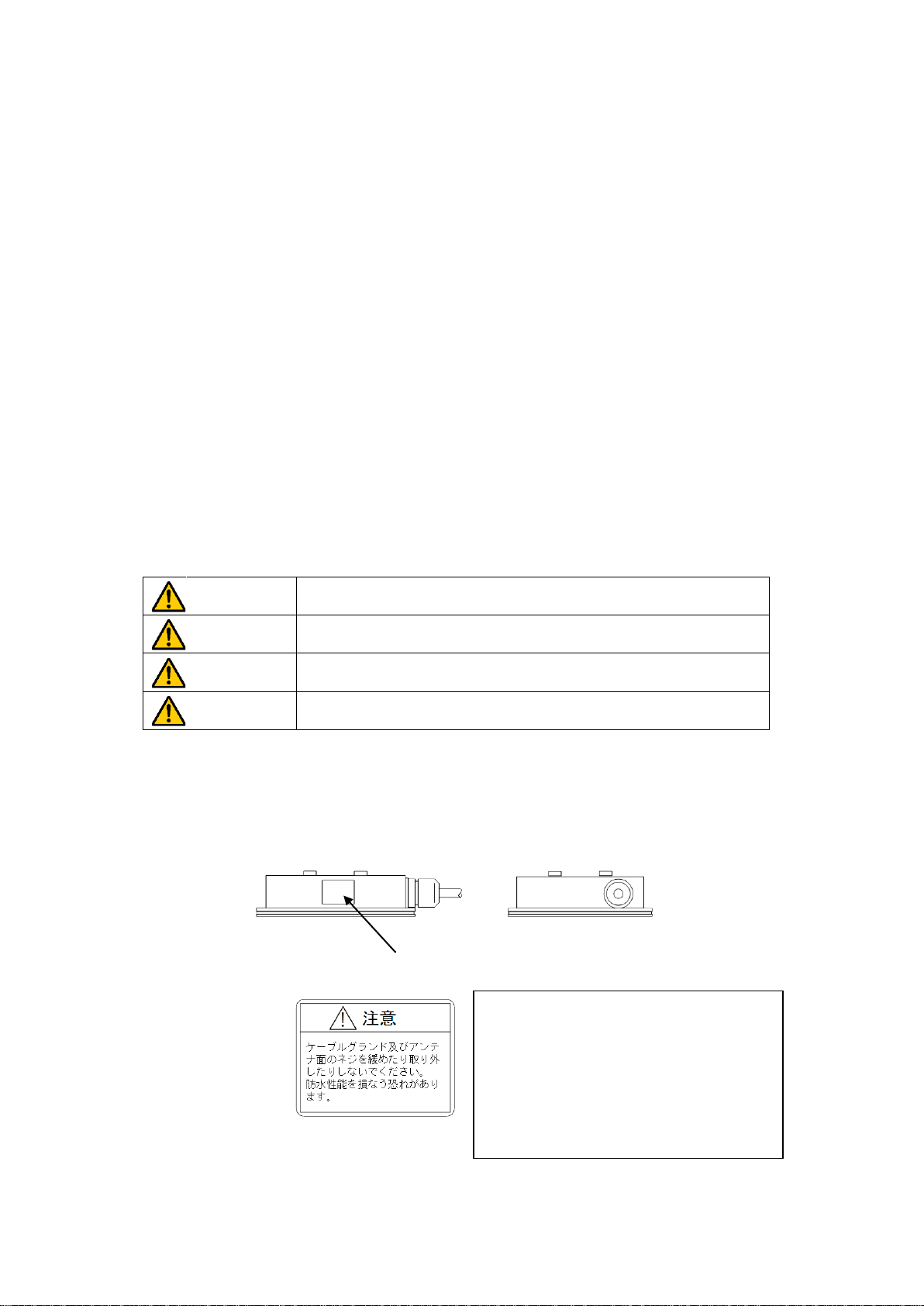
[Warning Label]
Indicates that incorrect usage may result in death or serious injury to the operator.
Warning Label
Left warning label means
Caution
Do not remove cable glands
or any
screws that attached with main unit. In
case of removal it, main unit can not
satisfy performance of protection
class.
( )1

Usage Precautions
This instrument is used to measure level height by means of microwave. For safe usage
and optimum performance of the radar level sensor, always operate the instrument
according to the usage precautions below.
CAUTION
1. Failure to comply with one or more of the following conditions may result in poor
measurement performance or incorrect measurement values.
・
Use an appropriate power supply rated for the voltage range designated in the
specifications.
・Do not subject the main unit to vibration or mechanical shock.
・Place the main unit, transducer and cable in a location without noise interference.
・Use the equi
pment within the predetermined ambient temperature and humidity
range.
2.
If the signal level is below the minimum detection requirement of the instrument, the
alarm will be reported through analog output in accordance with alarm setting.
3. Be sure to u
se the instructions in the Manual when changing settings on the main
unit. Incorrect settings will result in poor performance or incorrect measurement
values (output signals).
4. Do not modify or disassemble the unit. Such actions may result in electrical shock or
equipment damage.
5. If this Operation manual is lost, contact the nearest dealership.
( )2

Introduction
Thank you for your selecting our radar level sensor.
This Manual includes detailed explanations regarding safety cautions, structure, set up,
operation, troubleshooting, and maintenance of the radar level sensor.
Read this manual carefully before operation to ensure an adequate understanding of the
equipment.
Proper use of the Operation Manual
The following points must be observed:
CAUTION
1.
Carefully read the Manual. The contents of this Manual are very important and should
be read completely.
2.
Store the Manual in a safe location. The Manual is essential for appropriate operation
of the equipment. Store the manual in a safe and access
ible location. The storage
location and person in charge should be determined after careful consideration.
3.
Ensure that the Manual is supplied to the operator of the equipment. The
representative or dealer of this equipment must provide this Manual to the user who
will actually operate the equipment.
4.
The Manual must be replaced if lost or damaged. If the Manual is lost, contact the
representative. A new manual is available for purchase.
5. Ensure that the warning label is properly attached. If the warning label is illegible or
has come off, contact the manufacturer to purchase a new label.
Precautions regarding the Manual
This Manual was written in accordance with the standard specifications of the original
instrument.
In case of discrepancies between written specifications and approved drawings, the
drawings should be given precedence.
Restrictions and precautions necessary to maintain the equipment
The following items must be observed in order to maintain the equipment.
CAUTION
1. Do not drop or bump the unit and the transducer.
2.
Do not use the unit in environmental conditions (ambient temperature, ambient
humidity) other than those prescribed in this manual.
3. Do not use the unit with a power supply other than the one prescribed in this manual.
4. Do not use damaged or worn-
out cables (power cables, coaxial cables, signal
cables).
5.
Under no circumstances attempt to modify or disassemble the instrument. Contact
the manufacturer in the event of a malfunction.
6. Do not remove cable glands or any screws that
attached with main unit. In case of
removal it, main unit can not satisfy performance of protection class.
7. Do not modify or disassembl
e the unit. Such actions may result in electrical shock or
equipment damage.
8. Do not use the unit and/or accessories in restricted hazardous areas.
( )
3

Safety Precautions ……………………………………………………………………….. (1)
Usage Precautions ………………………………………………………………………..(2)
Introduction ………………………………………………………………………………...(3)
Proper use of the Operation Manual …………………………………………………… (3)
Precautions regarding to the Manual ………………………………………………….. (3)
Restrictions and precautions necessary to maintain the equipment ………………...(3)
INDEX
1. Product Description 1-1
1.1 Features 1-1
1.2 Measuring principle 1-1
1.3 MRF-10 measuring system 1-1
2. Mechanical Installation 2-1
2.1 Requirements 2-1
2.2 Beam area in the measuring range 2-2
2.3 Recommended installation example 2-3
(1) Installation for water channel 2-3
(2) Installation for storage tank 2-4
3. Electrical Installation 3-1
3.1 Wiring connection 3-1
(1) Transmitter side 3-1
(2) Connection fro commissioning software 3-2
3.2 Cables 3-2
3.3 Load 3-2
3.4 Power Supply 3-2
3.5 Grounding 3-3
(1) Connecting only with attached standard
cable or extended with 3-core shielded cable 3-3
(2) Extended 2-core cable with shield 3-3
(3) With lightening arrester 3-3
(4) When base of the mounting position made
by metal parts which connected
with the grounding line 3-4
4. Commissioning 4-1
4.1 Working conditions 4-1
4.2 Produced File 4-1
4.3 Connection 4-2
4.4 Initial Setup 4-2
(1) Startup Screen 4-2
(2) Reading HART ID 4-3
(3) Message after data communication 4-4
4.5 Basic Operation 4-5
(1) Read parameter 4-5
(2) Rewrite of parameters 4-6
4.6 Measuring Value 4-7
( )
4

(1) Monitoring of measuring value 4-7
(2) Logging the measured data 4-8
4.7 Tank Spectrum 4-9
(1) Plotting Tank Spectrum 4-9
(2) Zoom-in a part of spectrum 4-10
(3) Save spectrum data 4-11
4.8 Noise Table 4-12
(1) Plotting points 4-12
(2) Deleting data from noise table 4-14
4.9 Parameter instructions 4-15
5. Setup 5-1
5.1 Basic Parameters 5-1
5.2 Negative level measurement 5-1
5.3 Avoiding Disturbance Echoes 5-2
(1) Dead Band 5-2
(2) Noise table 5-2
5.4 Volume calculation 5-5
(1) Defined tanks 5-5
(2) User defined tank 5-6
5.5 Analog value compensation 5-7
(1) Analog check 5-7
(2) Analog calibration 5-7
5.6 Measuring value compensation 5-8
5.7 Bottom recognition 5-8
6. Technical Information 6-1
6.1 Main unit specification 6-1
(1) Main unit specification 6-1
(2) Power 6-1
(3) Output 6-1
(4) Accuracy 6-2
6.2 Environmental resistance 6-2
6.3 Construction 6-3
(1) Cable connection 6-3
(2) Material and Mass 6-3
6.4 Dimension 6-4
( )
5

(blank)
( )
6
1. Product Description
1.1 Features
The MRF-10 is a loop-powered radar level gauge, which can be installed easily in a
variety of applications. The MRF-10 employs a non-contact radar level gauging principle
based on pulsed microwave signals and is suitable for level measurement in applications
such as liquids, pastes and slurries.
MRF-10 uses 5.8GHz low power pulsed microwave. It provides good measurement
stability, because propagation of microwaves is less affected by change of temperature,
pressure or gas conditions in tank.
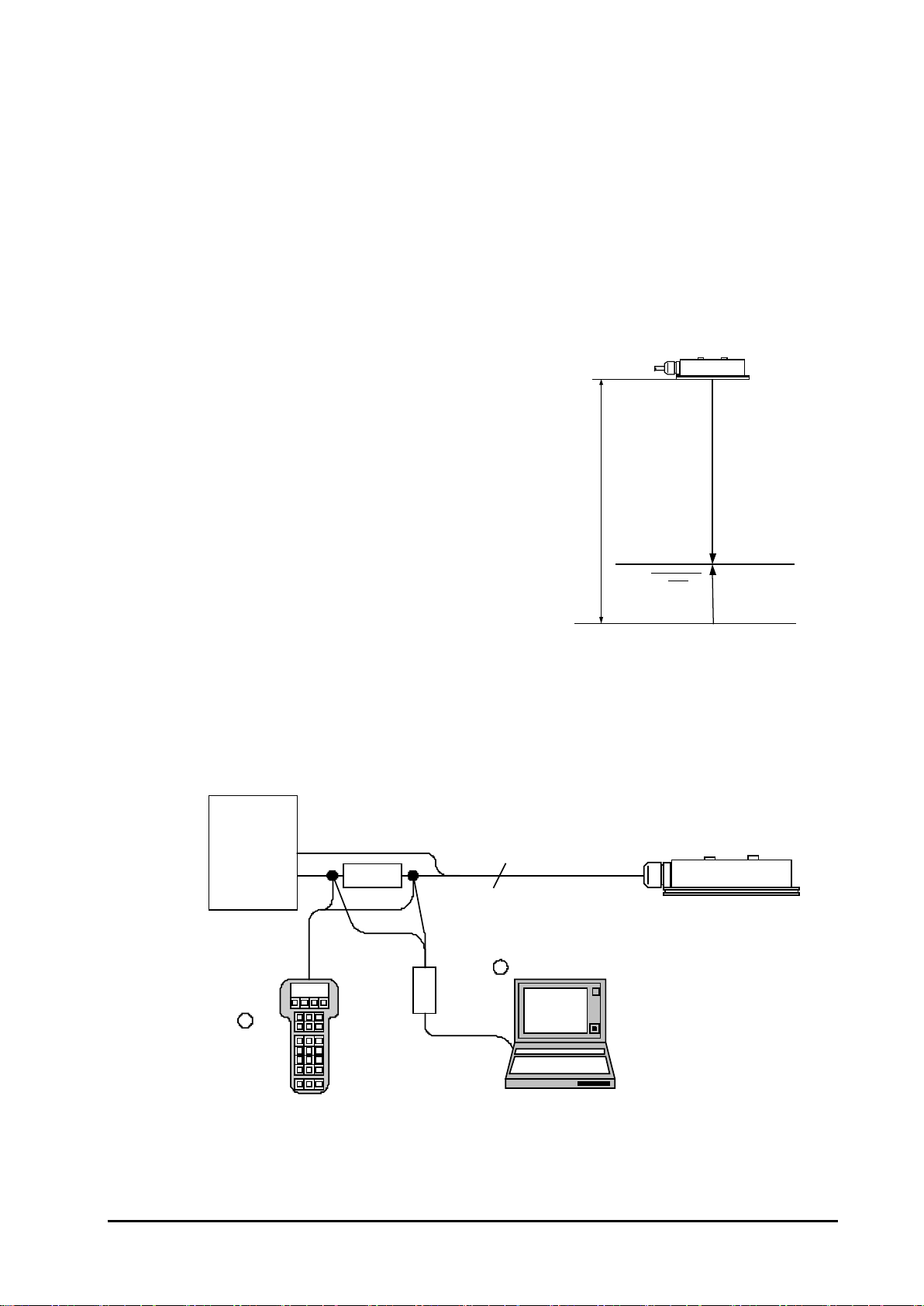
1.2 Measuring Principle
The MRF-10 level gauge utilizes the time-of-flight
measurement principle involving short microwave
pulses. Installed at the top of tanks or channels, it emits
short microwave pulses toward liquids or pastes.
Reflected microwave signals from the surface are
received by the antenna, and processed by electronics.
The time from transmission to reception is determined
by the microprocessor and converted as distance from
the transmitter to the liquid surface (ullage) with output
of the calculated level from the measured ullage (Level
= Tank Height – Ullage).
1.3 System configuration
MRF-10 can be configured with remotely from a personal computer via a modem or a
handheld terminal.
The MRF-10 is required to connect to a PLC or power supply unit.
Ullage
Level
Surface
TankHeight
MRF-10
HART
Modem
HART
Communicator
Power
Source Load
>250Ω
4...20mA
2
R
R
MRF-10
1-1

(blank)
1-2
2. Mechanical Installation
2.1 Requirements
Please regard to following points to install MRF-10 transmitter head.
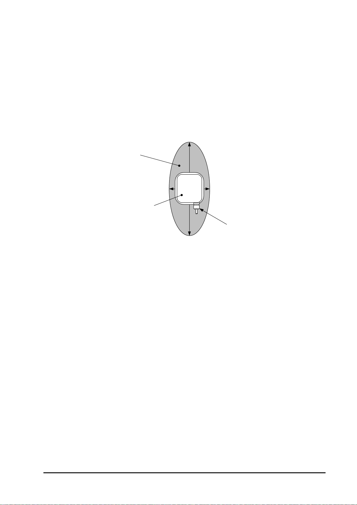
(1)Directivity angle of microwave
MRF-10 has elliptical (oval) directivity of microwave as below Fig. 2.1-1.
Please refer to chapter 2.3 example of recommended installation to install
transmitter head properly.
Fig. 2.1-1 Beam angle
(2)Free space requirement
The transmitter should be mounted so that no obstacles are present in the radar
beam. Obstacles in the radar beam may reduce the measuring range.
Please refer to list 2.2-1.
(3)Mounting allowance
Center of microwave radiation must be vertical against target fluid surface.
Allowance of the mounting angle should be +/- 1degree.
Beam angle23
°
(Crosswise direction)
Cable Entry
Beam angle 50
°
(Lengthwise direction)
Beam area
MRF-10
2-1
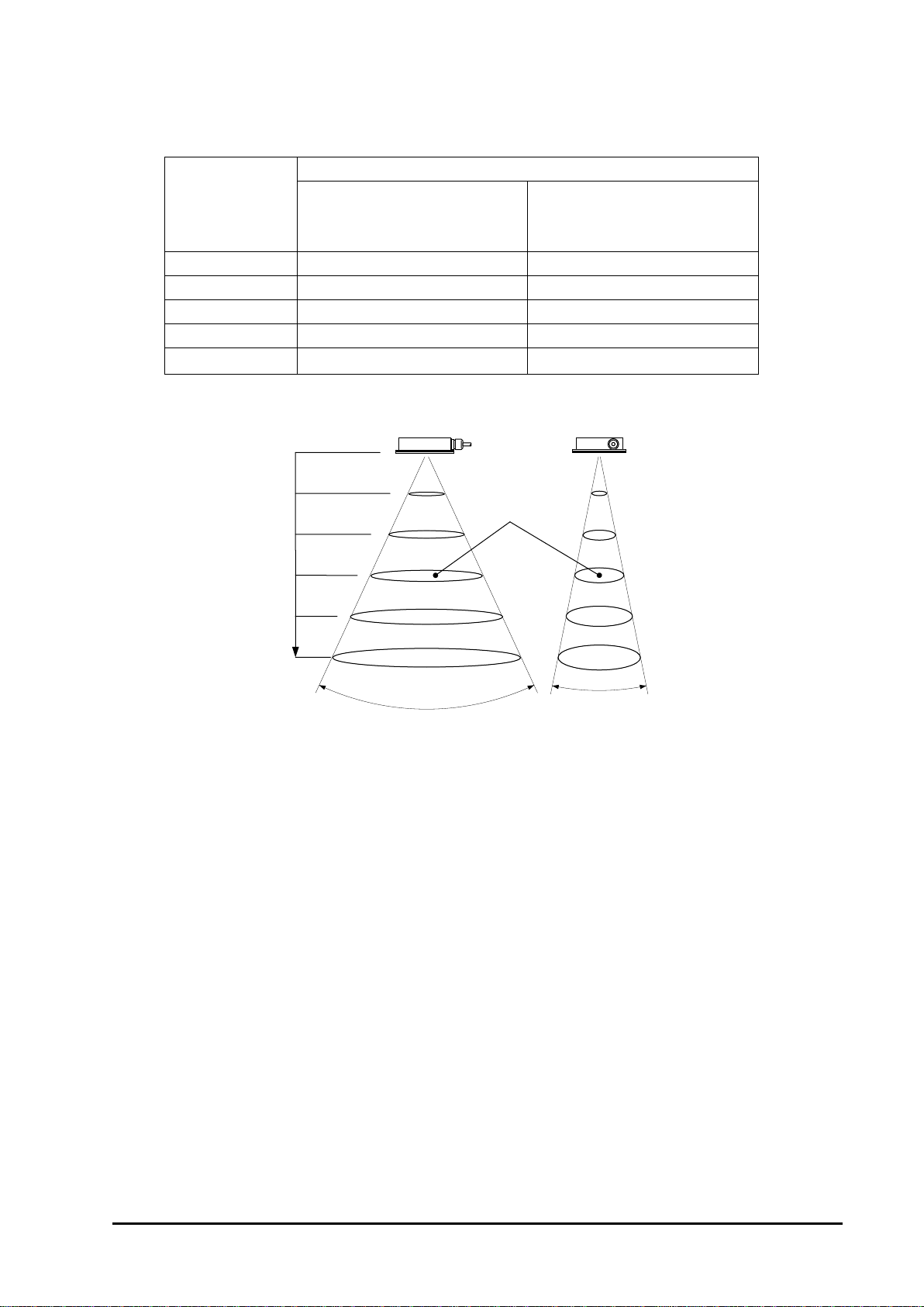
2.2 Beam area in the measuring range
List 2.2-1:Beam angle & Beam area (*-3dB Half-power beam angle)
Distance (m)
Beam area (m)
Lengthwise direction
(cable direction)
Beam angle
*
=50
°
Crosswise direction
Beam angle*=23°
2
1.9
0.8
4
3.7
1.6
6
5.5
2.4
8
7.5
3.3
10 9.3 4.1
[ Key factors for measurement ]
1. Compared to calm fluid surfaces, measuring ranges of turbulent surfaces are
reduced due to poorer reflection.
2. Deposit buildup on the antenna, foaming on liquid surfaces, powder granules in air
suspension and other interior tank conditions may affect measuring range and
performance.
3. Obstructions in the microwave radiating area or target fluid surface areas less than
the radiating area will reduce microwave reflection and decrease and narrow the
measurable range.
4. Measurable range may be varied when area of target fluid surface is smaller than
radiated beam area.
2m
4m
6m
8m
10m
Distance
23.0°
50.0°
Beam area
Long side
Short side
2-2

2.3 Recommended installation example
Following installation examples are recommended installations.
(1) Installation for water channel
Install MRF-10 lengthwise direction of transmitter head to be same direction of flow
direction as below.
Also please keep the required free space from the wall.
Fig. 2.3-1 example of wall sidemounting installation
Fig. 2.3-2 example of top roof mounting installation below grating cover
Wall
H
Required space =
H x 0.5
Water Channel
Flow Direction
Any obstructions must
not be on this wall.
H
Gratingcover
Concrete
slab
Gratingcover / Top roof mounting
Water Channel
Required space = H x 0.5
Flow Direction
2-3

Fig. 2.3-3 example of wall side mounting installation for Inlet water level measurement
(2) Installation for storage Tank
Please avoid installing MRF-10 at the very center of tank, because the reflection of
side beam will affect stable measurement.
Besides, please set the lengthwise direction of MRF-10 install to be parallel against
the nearest tank wall. In such case, required free space to the nearest tank wall will
be more than “measuring range x 0.2”.
Fig. 2.3-4 example of tank installation
Note
Any obstructions, which set as parallel to fluid surface in, the radiated beam area
may contain big disturbance noise.
In such case, reflection plate will be one of the solutions to reduce its reflection.
Tank Wall
H
Side of channel
mounting
Any obstructions must not be on this wall.
Water Channel
Flow Direction
Required space = H x 0.5
2-4
3. Electrical Installation
3.1 Wiring connection
(1) Transmitter side
!
Caution
Do not remove cable glands or any screws that attached with main unit. In case of
removal it, main unit can not satisfy performance of protection class.
Any cable work must be done at the end side of cable, not at the cable entry of the
main unit.
If cable extension is required, please use chemical binder at the end of cable to keep
water protection class.
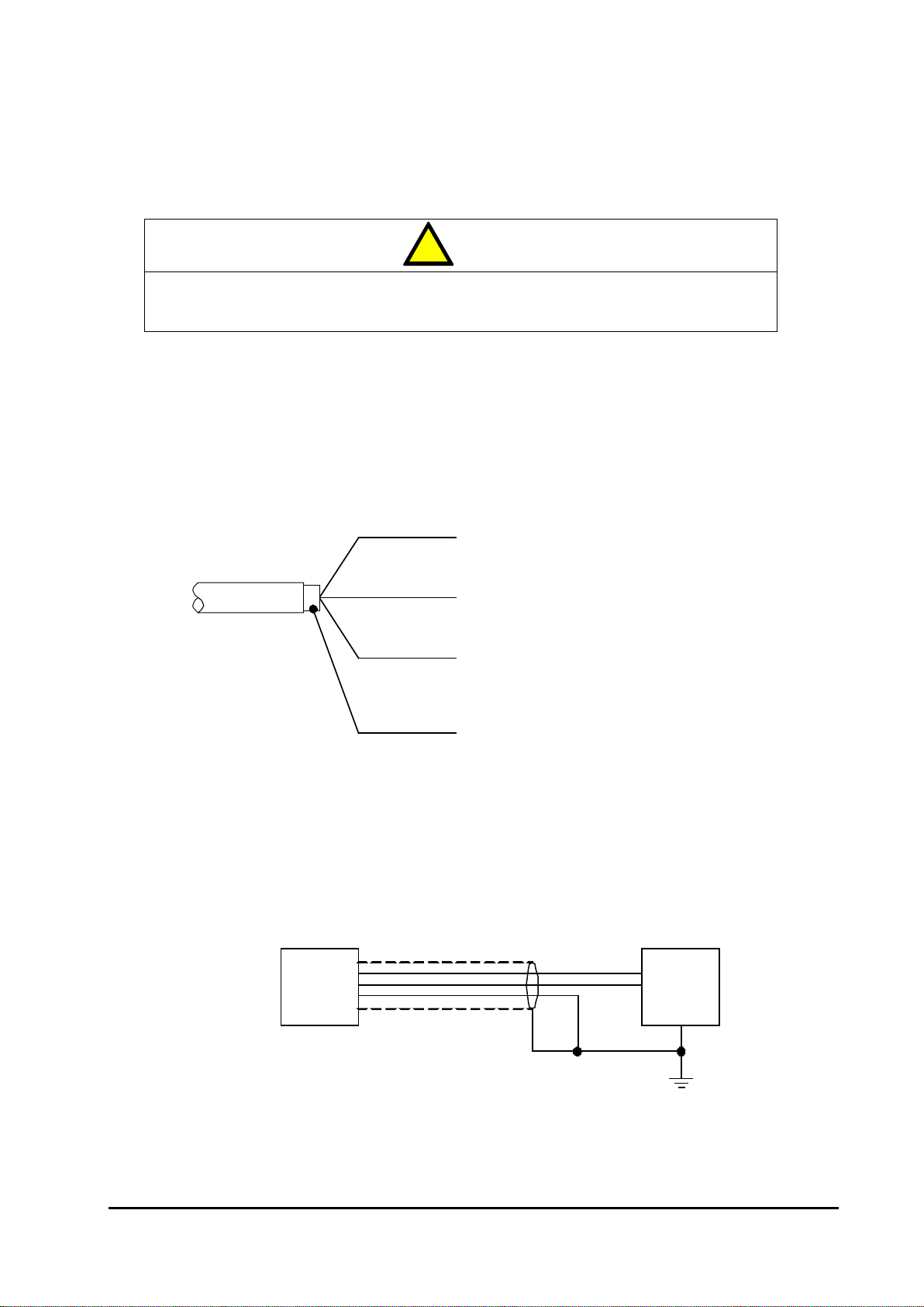
Fig. 3.1.1-1 wiring connection
・FG (frame ground) must be connected to ground line with cable shield as below.
Fig. 3.1.1-2 Standard wiring diagram
Connet to + side power line
Frame Ground
Connect to power line shield at cabinet side.
MRF-10 Cable
+ (blue)
- (white)
FG (yellow)
Shield
Connet to - side power line
Connect to the groung terminal of the cabinetwith cable shield line.
In case of grounding alreadyattransmitterhead side, do not
connectthis line to the ground line at the cabinet.
MRF-10 +
-
FG
Power
scource
+
-
Shield
MRF-10 standard cable
3-1
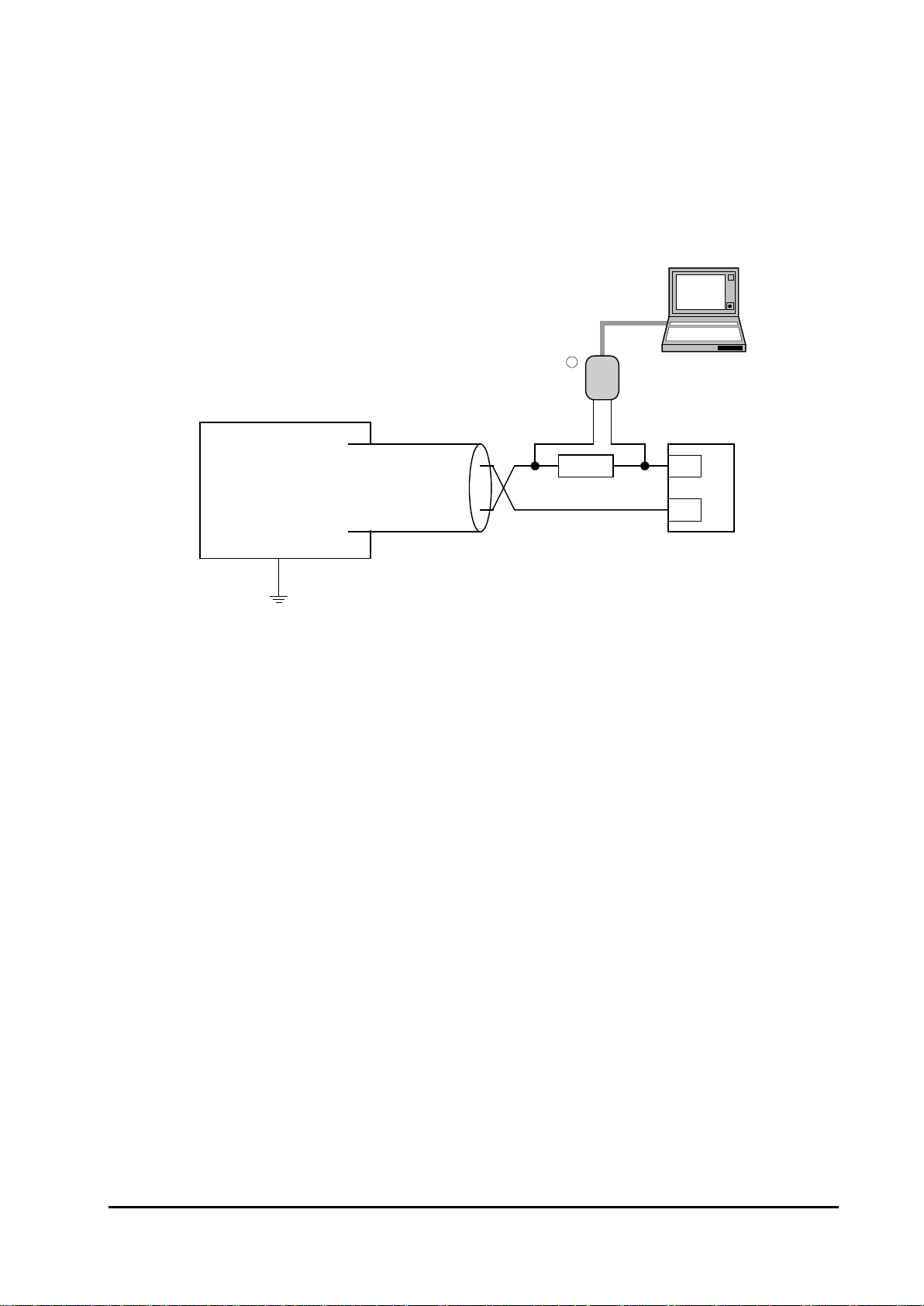
(2) Connection for commissioning software
Sample connection for commissioning software through PC is indicated as below
Fig.3.1.2-1.
Any analog recorder can be connected instead of Hart modem.
Fig. 3.1.2-1 Connection to commissioning software
3.2 Cables
Requirement Use shielded twisted cable 2-core or 3 core.
Cross-sectional area of conductor is 0.2 …2.5mm2.
(AWG24 …14)
Recommended cable; KNEE-SB (1.25sq x 3C, OD 9mm)
3.3 Load
Minimum load for HART®250Ω
Maximum load 340Ω(at DC24V)
3.4 Power supply
Requirement 16…36VCD
Current capacity 22mA
HART
modem
Power
Supply Unit
250Ω
-
+
R
MRF-10
3-2
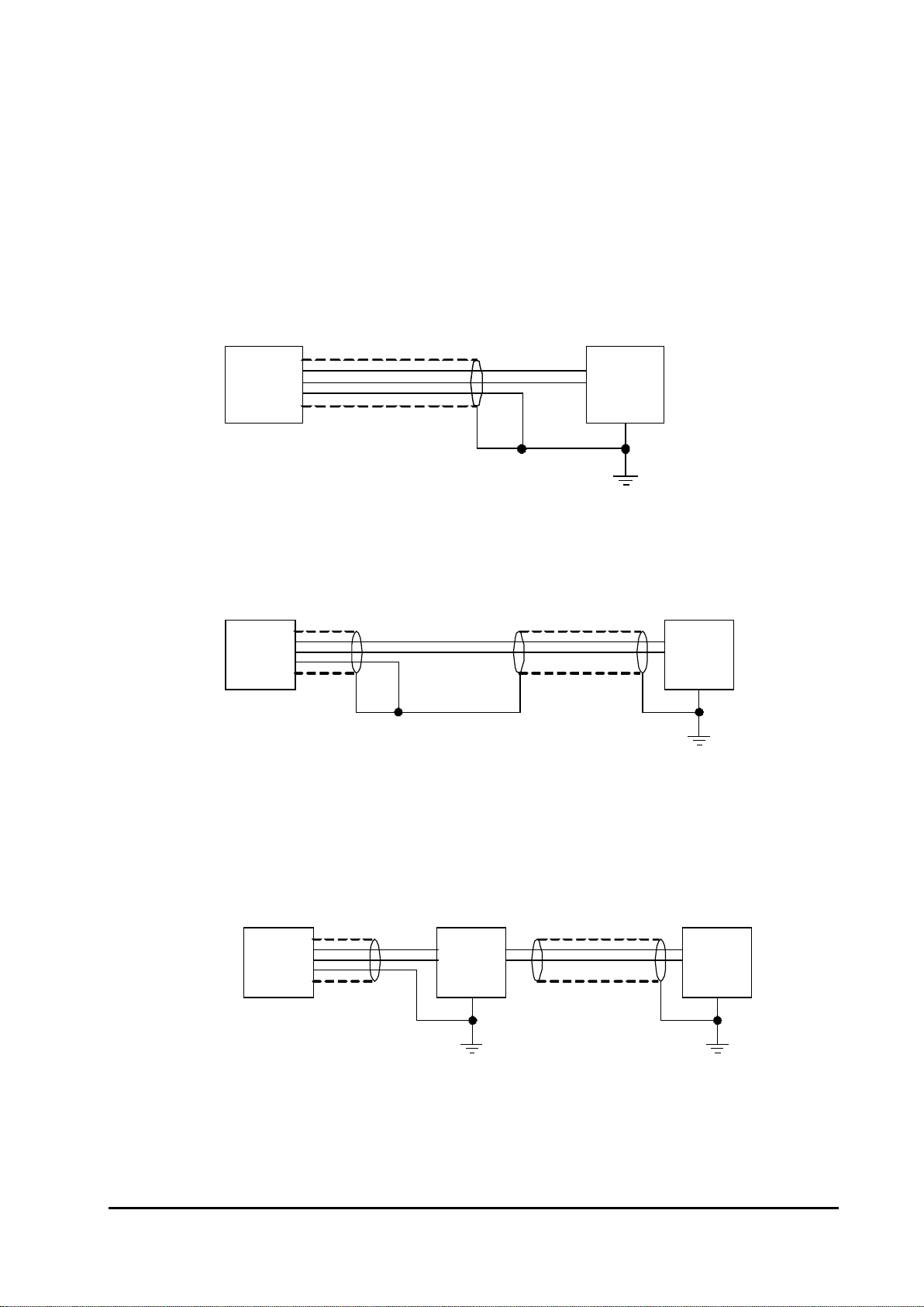
3.5 Grounding
The terminal must be connected to earth ground prior to connection to any other
equipment. The grounding resister should be less than 100 ohm.
(1) Example of connecting only with attached standard cable or extended with
3-core shielded cable
Please connect with shield & FG line to grounding line at power source side as
below.
(2) Extended 2-core cable with shield
Please connect shield line to FG line at connection part, then grounding at power
source side as below.
(3) With lightening arrester
Please connect only FG line to arrester grounding line.
The shield of extension line should be taken at ground line of power source side
as below.
The lightening arrester should be installed near-by MRF-10 transmitter head.
MRF-10 +
-
FG
Power
scource
+
-
Shield
MRF-10 standard cable
MRF-10 +
-FG
Power
source
+
-
Shield
Extention cable
MRF-10 Arrester
+
-
FG
+
-
Extention cable Power
source
3-3

(4) When base of the mounting position made by metal parts which connected
with the grounding line already.
Please connect the grounding terminal near by cable entry to the ground.
Do not use FG line, only with cable shield connects to grounding line as below.
MRF-10 +
-
FG
+
-Power
source
Shield
MRF-10 +
-
FG
+
-
Extention cable Power
source
Shield
Grounding
Terminal
3-4
4. Commissioning
4.1 Working Conditions
Microsoft Windows 2000 / XP
Personal Computer which can activate HART modem
HART Modem (* We have checked following products in the market.)
Maker : MAC Tek
Modem : VIATOR RS232 HART Interface (Model 010001)
VIATOR USB HART Interface (Model 010031)
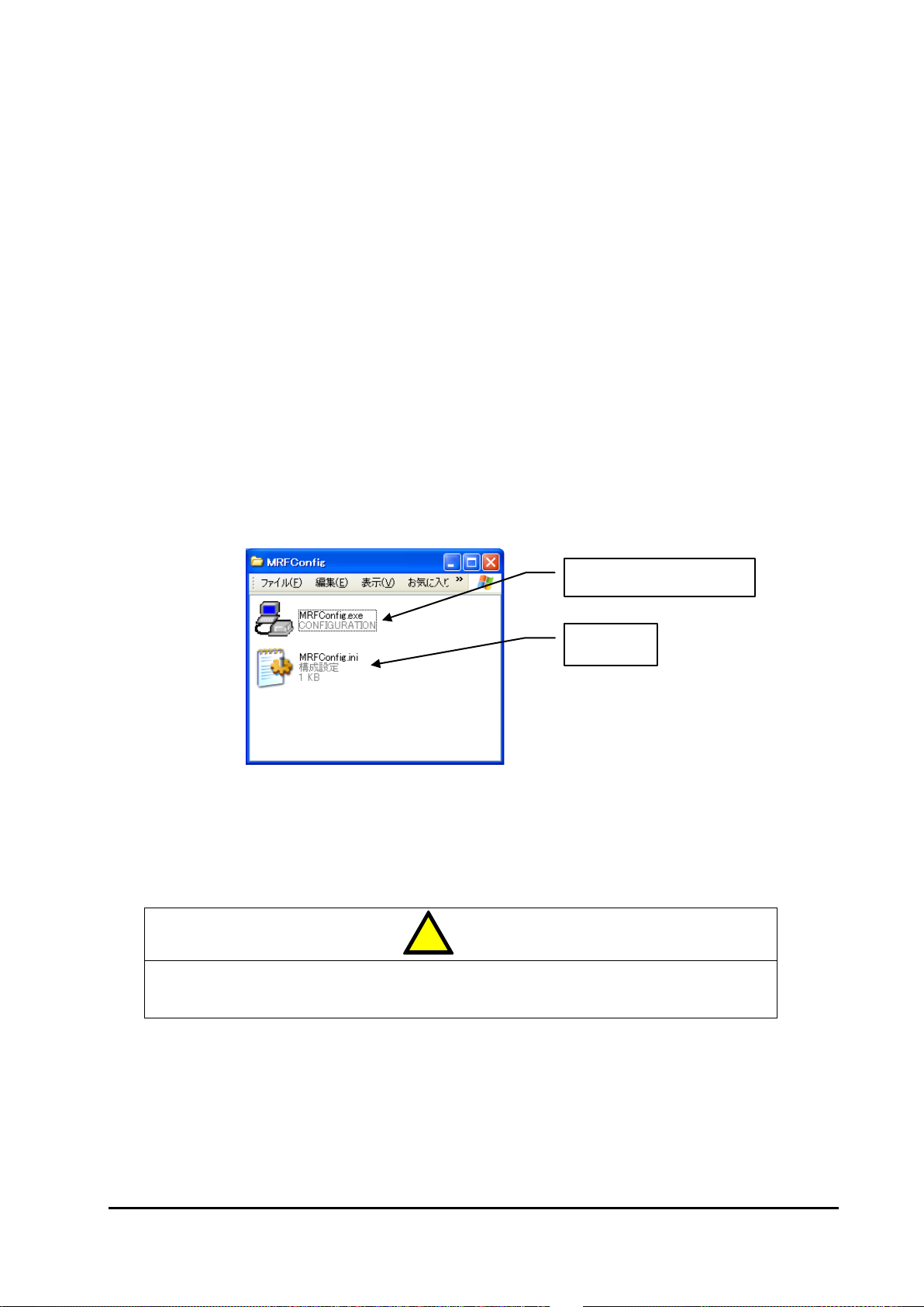
4.2 Produced file
MRFConfig.exe : Main program of configuration software
MRFConfig.ini : Initial File (When the configuration software was quitted, this file is
automatically created.)
Note
This software has no installer. Hence, please copy all files to any folder.
!
Caution
Carefully read this manual prior to use this software because incorrect operation will
cause malfunction and/or breakdown.
This software is subject to change for upgrade without prior notice
Initial File
Configuration Software
4-1
4.3. Connection
This sensor can setup by dedicated software on Notebook PC that connects with HART
modem.
As Fig1.1, HART modem connects with both end of load resister.
Fig. 1.1 Wiring
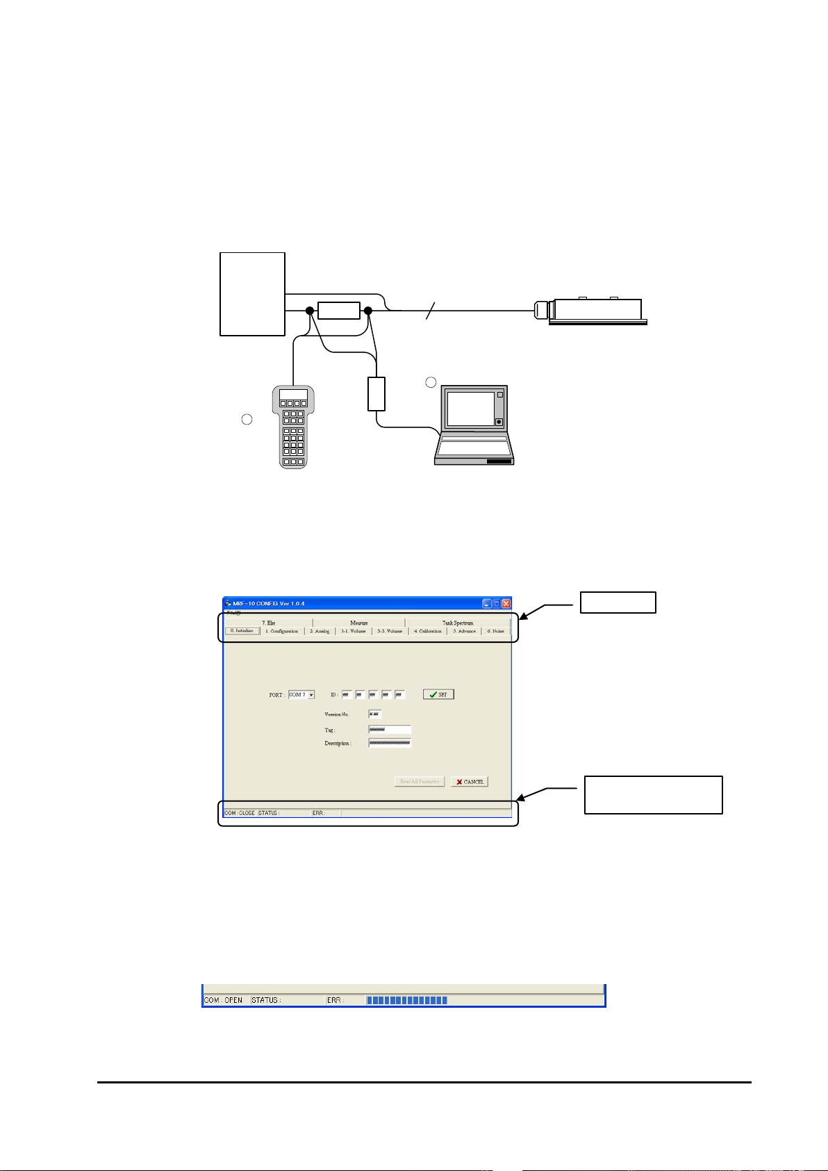
4.4 Initial Setup
(1) Startup Screen
Fig. 4.4-1 is Start-up Screen.
Fig. 4.4-1 Start-up Screen
Menu Tab in Fig. 4.4-1 can select each kind of parameter.
Progress bar at the lower-end of window shows communication status.
Fig. 4.4-2 is the progress bar under communication (online).
Fig. 4.4-2 Progress bar
Menu Tab
Progress bar to show
communication status
HART
Modem
HART
Handheld
Power
Supply
Load
>250Ω
4...20mA
2
R
R
MRF
-
10
Communicator
4-2

(2) Reading HART ID
Get HART ID from MRF-10.
Fig. 4.4-3 Start-up Screen after getting HART ID
Select serial port No. that connected with HART modem from PORT column in Fig.
4.4-3 at first.
Secondly, click [SET]button and download HART ID from the sensor.
After download of HART ID, individual ID and software version No. will be filled in each
column. All communication with MRF-10 will use this ID.
Fig. 4.4-4 After getting HART ID
[SET] button: Retrieve HART ID from the sensor.
[Read All Parameter]button: Retrieve all parameters from the sensor at one time.
[Cancel] button: Interrupt communication with the sensor on the way.
HART ID No.
Select serial port number.
Get ID by [SET] button.
Download all parameters
Cancel download
4-3
Table of contents
Popular Accessories manuals by other brands


incubato
incubato IN-7DDI user manual

R-Biopharm
R-Biopharm Premi Test Technical manual

Rockwell Automation
Rockwell Automation Allen-Bradley 875L AC user manual

Nooploop
Nooploop TOFSense-F user manual

Parker
Parker Sporlan SD-245 Installation and servicing instructions

Waeco
Waeco CoolPower MPS50 Installation and operating manual


