Vega VEGABAR 39 User manual

Operating Instructions
Pressure sensor with metallic measuring
cell
VEGABAR 39
Two-wire 4 … 20 mA
Document ID: 57089

2
Contents
VEGABAR 39 • Two-wire 4 … 20 mA
57089-EN-220826
Contents
1 About this document ............................................................................................................... 4
1.1 Function ........................................................................................................................... 4
1.2 Target group ..................................................................................................................... 4
1.3 Symbols used................................................................................................................... 4
2 For your safety ......................................................................................................................... 5
2.1 Authorised personnel ....................................................................................................... 5
2.2 Appropriate use................................................................................................................ 5
2.3 Warning about incorrect use............................................................................................. 5
2.4 General safety instructions............................................................................................... 5
2.5 Installation and operation in the USA and Canada ........................................................... 5
3 Product description ................................................................................................................. 7
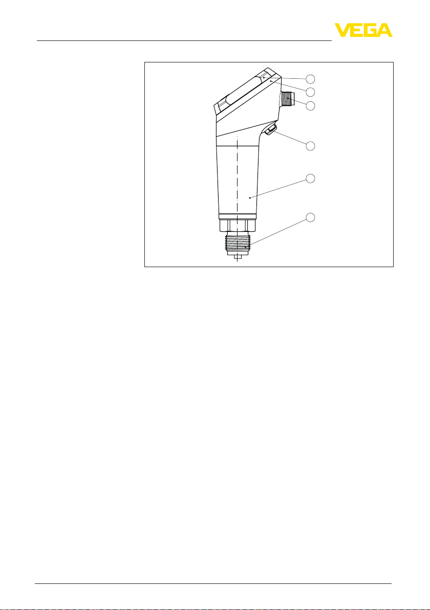
3.1 Conguration.................................................................................................................... 7
3.2 Principle of operation........................................................................................................ 9
3.3 Adjustment ..................................................................................................................... 11
3.4 Packaging, transport and storage................................................................................... 12
3.5 Accessories.................................................................................................................... 13
4 Mounting................................................................................................................................. 14
4.1 General instructions ....................................................................................................... 14
4.2 Process pressure measurement..................................................................................... 16
4.3 Level measurement........................................................................................................ 18
5 Connecting to power supply................................................................................................. 19
5.1 Preparing the connection ............................................................................................... 19
5.2 Connection procedure.................................................................................................... 19
5.3 Wiring plan - Two-wire 4 … 20 mA.................................................................................. 22
5.4 Switch-on phase............................................................................................................. 23
6 Access protection.................................................................................................................. 24
6.1 Bluetooth radio interface ................................................................................................ 24
6.2 Protection of the parameterization.................................................................................. 24
6.3 Storing the codes in myVEGA........................................................................................ 25
7 Set up with the integrated display and adjustment unit .................................................... 26
7.1 Adjustment system......................................................................................................... 26
7.2 Measured value and menu item display ......................................................................... 27
7.3 Parameter adjustment .................................................................................................... 28
8 Setup with smartphone/tablet (Bluetooth).......................................................................... 35
8.1 Preparations................................................................................................................... 35
8.2 Connecting..................................................................................................................... 35
8.3 Sensor parameter adjustment........................................................................................ 36
9 Setup with PC/notebook (Bluetooth)................................................................................... 37
9.1 Preparations................................................................................................................... 37
9.2 Connecting..................................................................................................................... 37
9.3 Parameter adjustment .................................................................................................... 38
10 Menu overview ....................................................................................................................... 39
10.1 Display and adjustment unit (on site).............................................................................. 39
10.2 VEGA Tools app and DTM (Bluetooth) ........................................................................... 40

3
Contents
VEGABAR 39 • Two-wire 4 … 20 mA
57089-EN-220826
11 Diagnostics and servicing .................................................................................................... 42
11.1 Maintenance .................................................................................................................. 42
11.2 Rectify faults................................................................................................................... 42
11.3 Diagnosis, fault messages ............................................................................................. 43
11.4 Status messages according to NE 107 .......................................................................... 43
11.5 Software update ............................................................................................................. 45
11.6 How to proceed if a repair is necessary.......................................................................... 46
12 Dismount................................................................................................................................. 47
12.1 Dismounting steps.......................................................................................................... 47
12.2 Disposal ......................................................................................................................... 47
13 Certicatesandapprovals.................................................................................................... 48
13.1 Radio licenses................................................................................................................ 48
13.2 Approvals for Ex areas ................................................................................................... 48
13.3 Approvalsasoverllprotection....................................................................................... 48
13.4 Foodandpharmaceuticalcerticates............................................................................. 48
13.5 Conformity...................................................................................................................... 48
13.6 NAMUR recommendations ............................................................................................ 48
13.7 Environment management system ................................................................................. 49
14 Supplement ............................................................................................................................ 50
14.1 Technical data ................................................................................................................ 50
14.2 Dimensions .................................................................................................................... 59
14.3 Industrial property rights................................................................................................. 64
14.4 Licensing information for open source software ............................................................. 64
14.5 Trademark ...................................................................................................................... 64
Safety instructions for Ex areas:
TakenoteoftheExspecicsafetyinstructionsforExapplications.
These instructions are attached as documents to each instrument
with Ex approval and are part of the operating instructions.
Editing status: 2022-08-25

4
1 About this document
VEGABAR 39 • Two-wire 4 … 20 mA
57089-EN-220826
1 About this document
1.1 Function
This instruction provides all the information you need for mounting,
connection and setup as well as important instructions for mainte-
nance,faultrectication,theexchangeofpartsandthesafetyofthe
user. Please read this information before putting the instrument into
operation and keep this manual accessible in the immediate vicinity
of the device.
1.2 Target group
This operating instructions manual is directed to trained personnel.
Thecontentsofthismanualmustbemadeavailabletothequalied
personnel and implemented.
1.3 Symbols used
Document ID
This symbol on the front page of this instruction refers to the Docu-
ment ID. By entering the Document ID on www.vega.com you will
reach the document download.
Information, note, tip: This symbol indicates helpful additional infor-
mation and tips for successful work.
Note: This symbol indicates notes to prevent failures, malfunctions,
damage to devices or plants.
Caution: Non-observance of the information marked with this symbol
may result in personal injury.
Warning: Non-observance of the information marked with this symbol
may result in serious or fatal personal injury.
Danger: Non-observance of the information marked with this symbol
results in serious or fatal personal injury.
Ex applications
This symbol indicates special instructions for Ex applications.
• List
The dot set in front indicates a list with no implied sequence.
1 Sequence of actions
Numbers set in front indicate successive steps in a procedure.
Disposal
This symbol indicates special instructions for disposal.

5
2 For your safety
VEGABAR 39 • Two-wire 4 … 20 mA
57089-EN-220826
2 For your safety
2.1 Authorised personnel
All operations described in this documentation must be carried out
onlybytrained,qualiedpersonnelauthorisedbytheplantoperator.
During work on and with the device, the required personal protective
equipment must always be worn.
2.2 Appropriate use
The VEGABAR 39 is a pressure transmitter for process pressure and
hydrostatic level measurement.
Youcannddetailedinformationabouttheareaofapplicationin
chapter " Product description".
Operational reliability is ensured only if the instrument is properly
usedaccordingtothespecicationsintheoperatinginstructions
manual as well as possible supplementary instructions.
2.3 Warning about incorrect use
Inappropriate or incorrect use of this product can give rise to applica-
tion-specichazards,e.g.vesseloverllthroughincorrectmounting
or adjustment. Damage to property and persons or environmental
contamination can result. Also, the protective characteristics of the
instrument can be impaired.
2.4 General safety instructions
This is a state-of-the-art instrument complying with all prevailing
regulations and directives. The instrument must only be operated in a
technicallyawlessandreliablecondition.Theoperatorisresponsi-
ble for the trouble-free operation of the instrument. When measuring
aggressive or corrosive media that can cause a dangerous situation
if the instrument malfunctions, the operator has to implement suitable
measures to make sure the instrument is functioning properly.
The safety instructions in this operating instructions manual, the na-
tional installation standards as well as the valid safety regulations and
accident prevention rules must be observed by the user.
For safety and warranty reasons, any invasive work on the device
beyond that described in the operating instructions manual may be
carried out only by personnel authorised by the manufacturer. Arbi-
traryconversionsormodicationsareexplicitlyforbidden.Forsafety
reasons,onlytheaccessoryspeciedbythemanufacturermustbe
used.
To avoid any danger, the safety approval markings and safety tips on
the device must also be observed.
2.5 Installation and operation in the USA and
Canada
This information is only valid for USA and Canada. Hence the follow-
ing text is only available in the English language.

6
2 For your safety
VEGABAR 39 • Two-wire 4 … 20 mA
57089-EN-220826
Installations in the US shall comply with the relevant requirements of
the National Electrical Code (ANSI/NFPA 70).
Installations in Canada shall comply with the relevant requirements of
the Canadian Electrical Code.

7
3 Product description
VEGABAR 39 • Two-wire 4 … 20 mA
57089-EN-220826
3 Product description
3.1 Conguration
The scope of delivery encompasses:
• VEGABAR 39 pressure transmitter
• Information sheet " Documents and software" with:
– Instrument serial number
– QR code with link for direct scanning
• Information sheet " PINs and Codes" (with Bluetooth versions)
with:
– Bluetooth access code
• Information sheet " Access protection" (with Bluetooth versions)
with:
– Bluetooth access code
– Emergency Bluetooth unlock code
– Emergency device code
The further scope of delivery encompasses:
• Documentation
– Quick setup guide VEGABAR 39
– Ex-specic"Safety instructions" (with Ex versions)
– Radio approvals (versions with Bluetooth)
– Ifnecessary,furthercerticates
Note:
Optional instrument features are also described in this operating
instructions manual.The respective scope of delivery results from the
orderspecication.
This operating instructions manual applies to the following instrument
versions:
• Hardware version from 1.0.0
• Software version from 1.3.0
Scope of delivery
Scope of this operating
instructions

8
3 Product description
VEGABAR 39 • Two-wire 4 … 20 mA
57089-EN-220826
4
5
6
1
2
3
Fig. 1: Components of VEGABAR 39
1 Processtting
2 Electronics housing
3 Ventilation/pressure compensation
4 Plug connector
5 LED illuminated ring
6 Display/adjustment unit
Thetypelabelcontainsthemostimportantdataforidenticationand
use of the instrument.
Constituent parts
Type label

9
3 Product description
VEGABAR 39 • Two-wire 4 … 20 mA
57089-EN-220826
0044
4...20mA
12V...35V
3
2
1
4
5
6
PP - 222 329 22B s/n 12345678
IP66/IP67/69, TYPE 6P
MWP 33bar (3300kPa)
0...2,5bar (0...250kPa) rel
AL203, FKM, 316L
2019
www.vega.com
D-77761 SCHILTACH,
Made in Germany
+
-
2
4
1
3
123456
Fig. 2: Layout of the type label (example)
1 Order/Serial number
2 Field for approvals
3 Technical data
4 Assignment
5 Bluetooth access code
6 QR code for device documentation
Move to " www.vega.com"andenterinthesearcheldtheserial
number of your instrument.
Thereyoucanndthefollowinginformationabouttheinstrument:
• Order data
• Documentation
• Software
Alternatively,youcanndallviayoursmartphone:
• Scan the QR-code on the type label of the device or
• Enter serial number manually in the VEGA Tools app (available
free of charge in the respective stores)
3.2 Principle of operation
The VEGABAR 39 is suitable for the measurement of the following
process variables:
• Process pressure
• Level
Documents and software
Measured variables

10
3 Product description
VEGABAR 39 • Two-wire 4 … 20 mA
57089-EN-220826
Fig. 3: Process pressure measurement VEGABAR 39
VEGABAR 39 is suitable for applications in virtually all industries. It is
used for the measurement of the following pressure types.
• Gauge pressure
• Absolute pressure
• Vacuum
Measured products are gases, vapours and liquids.
The device is especially suitable for applications with higher tempera-
tures and high pressures.
The process pressure acts on the sensor element via the process dia-
phragm.The process pressure causes a resistance change which is
converted into a corresponding output signal and output as measured
value.
Piezoresistive sensor element
Measuring ranges up to and including 100 bar: piezoresistive sensor
element with internal isolating liquid is used.
4
1
3
2
Fig.4:Congurationofthemeasuringsystemwithpiezoresistivesensorele-
ment
1 Diaphragm
2 Isolating liquid
3 Base element
4 Sensor element
Application area
Measured products
Measuring system

11
3 Product description
VEGABAR 39 • Two-wire 4 … 20 mA
57089-EN-220826
Strain gauge (DMS) sensor element
For measuring ranges above and including 250 bar, a strain gauge
(DMS) sensor element (dry system) is used. 1)
3
2
1
Fig.5:Congurationofthemeasuringsystemwithstraingauge(DMS)sensor
element
1 Pressure cylinder
2 Process diaphragm
3 Sensor element
A temperature sensor on the respective sensor element for pressure
records the current process temperature.The temperature value is
output via Bluetooth, for example.
Relative pressure: the measuring cell is open to the atmosphere.
The ambient pressure is detected in the measuring cell and compen-
sated.Itthushasnoinuenceonthemeasuredvalue.
Absolute pressure: the measuring cell contains vacuum and is
encapsulated. The ambient pressure is not compensated and does
henceinuencethemeasuredvalue.
The measuring system is completely welded and thus sealed against
the process.
Theprocessttingissealedagainsttheprocessbyasuitableseal.It
mustbeprovidedbythecustomer,dependingontheprocesstting
also included in the scope of delivery, see chapter " Technical data", "
Materialsandweights".
3.3 Adjustment
The integrated display and adjustment unit is used for on-site adjust-
ment of VEGABAR 39.
For convenient reading and operation in any installation position
of the device, the housing and display and adjustment unit can be
rotated without tools.
Measuring system tem-
perature
Pressure types
Seal concept
Local adjustment
1) For cleaning procedures "free of oil, grease and silicone for oxygen applica-
tions" also for measuring range 100 bar

12
3 Product description
VEGABAR 39 • Two-wire 4 … 20 mA
57089-EN-220826
1
2
1 Rotating the housing by 330°
1 Rotating the display and adjustment unit by 270°
Devices with integrated Bluetooth module can be adjusted wirelessly
via standard adjustment tools:
• Smartphone/tablet (iOS or Android operating system)
• PC/notebook (Windows operating system)
1
3
2
Fig. 6: Wireless connection to standard operating devices with integrated
Bluetooth LE
1 Sensor
2 Smartphone/Tablet
3 PC/Notebook
3.4 Packaging, transport and storage
Your instrument was protected by packaging during transport. Its
capacity to handle normal loads during transport is assured by a test
based on ISO 4180.
The packaging consists of environment-friendly, recyclable card-
board. For special versions, PE foam or PE foil is also used. Dispose
of the packaging material via specialised recycling companies.
Transport must be carried out in due consideration of the notes on the
transport packaging. Nonobservance of these instructions can cause
damage to the device.
Wireless adjustment
Packaging
Transport

13
3 Product description
VEGABAR 39 • Two-wire 4 … 20 mA
57089-EN-220826
The delivery must be checked for completeness and possible transit
damage immediately at receipt. Ascertained transit damage or con-
cealed defects must be appropriately dealt with.
Up to the time of installation, the packages must be left closed and
stored according to the orientation and storage markings on the
outside.
Unless otherwise indicated, the packages must be stored only under
the following conditions:
• Not in the open
• Dry and dust free
• Not exposed to corrosive media
• Protected against solar radiation
• Avoiding mechanical shock and vibration
• Storage and transport temperature see chapter " Supplement -
Technical data - Ambient conditions"
• Relative moisture 20 … 85 %
3.5 Accessories
The instructions for the listed accessories can be found in the down-
load area on our homepage.
Welded sockets are used to connect the devices to the process.
Threaded and hygienic adapters enable simple adaptation of devices
withstandardthreadedttingstoprocess-sidehygieneconnections.
The suitable mounting accessories for VEGABAR 39 includes si-
phons, blocking valves and measuring instrument holders.
Transport inspection
Storage
Storage and transport
temperature
Welded socket, threaded
and hygienic adapter
Mounting accessories

14
4 Mounting
VEGABAR 39 • Two-wire 4 … 20 mA
57089-EN-220826
4 Mounting
4.1 General instructions
The instrument is suitable for standard and extended ambient condi-
tions acc. to DIN/EN/IEC/ANSI/ISA/UL/CSA 61010-1. It can be used
indoors as well as outdoors.
Note:
For safety reasons, the instrument must only be operated within the
permissibleprocessconditions.Youcannddetailedinformationon
the process conditions in chapter " Technical data" of the operating
instructions or on the type label.
Hence make sure before mounting that all parts of the instrument ex-
posed to the process are suitable for the existing process conditions.
These are mainly:
• Active measuring component
• Processtting
• Process seal
Process conditions in particular are:
• Process pressure
• Process temperature
• Chemical properties of the medium
• Abrasionandmechanicalinuences
Thepermissibleprocesspressurerangeisspeciedby"MWP"(Maxi-
mum Working Pressure) on the type label, see chapter " Structure".
The MWP takes the element of the measuring cell and processing
ttingcombinationwiththeweakestpressureintoconsiderationand
mayappliedpermanently.Thespecicationreferstoareference
temperature of +20 °C (+68 °F). It also applies when a measuring cell
with a higher measuring range than the permissible pressure range of
theprocessttingisinstalledorder-related.
Inaddition,atemperaturederatingoftheprocesstting,e.g.with
anges,canlimitthepermissibleprocesspressurerangeaccording
to the respective standard.
Note:
In order to prevent damage to the device, a test pressure may only
exceedthespeciedMWPbrieyby1.5timesatreferencetempera-
ture.Thepressurestageoftheprocessttingaswellastheoverload
resistance of the measuring cell are taken into consideration here
(see chapter " Technical Data").
Protect your instrument against moisture ingress through the following
measures:
• Use a suitable connection cable (see chapter " Connecting to
power supply")
• Tighten the cable gland or plug connector
Ambient conditions
Process conditions
Permissible process
pressure (MWP) - Device
Protection against mois-
ture

15
4 Mounting
VEGABAR 39 • Two-wire 4 … 20 mA
57089-EN-220826
• When mounting horizontally, rotate the housing so that the cable
gland or plug connector point downward
• Lead the connection cable downward in front of the cable entry or
plug connector
This applies mainly to outdoor installations, in areas where high
humidity is expected (e.g. through cleaning processes) and on cooled
or heated vessels.
Makesurethatthedegreeofcontaminationspeciedinchapter"
Technical data" meets the existing ambient conditions.
Ventilation and pressure compensation for VEGABAR 39 are provided
byanair-permeable,moisture-blockinglterelement.
Note:
Incaseofhorizontalmounting,turnthehousingsothatthelterele-
ment points downward after the instrument is installed. This provides
better protection against buildup.
1
Fig.7:Positionofthelterelement
1 Filter element
Foreectiveventilation,thelterelementmustalwaysbefreeof
buildup.
Deviceswiththreadedttingarescrewedintotheprocessttingwith
a suitable wrench via the hexagon.
See chapter " Dimensions" for wrench size.
Warning:
The housing or the electrical connection may not be used for screw-
ing in! Depending on the device version, tightening can cause dam-
age, e. g. to the rotation mechanism of the housing.
The permissible process pressure range is stated on the type label.
The instrument should only be operated with these pressures if the
mountingaccessoryusedalsofullsthesevalues.Thisshouldbeen-
suredbysuitableanges,weldedsockets,tensionringswithClamp
connections, sealings, etc.
Higher process temperatures often mean also higher ambient
temperatures. Make sure that the upper temperature limits stated in
chapter " Technical data" for the environment of the electronics hous-
ing and connection cable are not exceeded.
Ventilation and pressure
compensation
Screwing in
Permissible process
pressure (MWP) - Mount-
ing accessory
Temperature limits

16
4 Mounting
VEGABAR 39 • Two-wire 4 … 20 mA
57089-EN-220826
1
2
Fig. 8: Temperature ranges
1 Process temperature
2 Ambient temperature
4.2 Process pressure measurement
Keep the following in mind when setting up the measuring system:
• Mount the instrument above the measuring point
Possiblecondensationcanthendrainointotheprocessline.
1
2
3
Fig.9:Measurementsetupforprocesspressuremeasurementofgasesin
pipelines
1 VEGABAR 39
2 Blocking valve
3 Pipeline
Keep the following in mind when setting up the measuring system:
• Connect via a siphon
In gases
In vapours

17
4 Mounting
VEGABAR 39 • Two-wire 4 … 20 mA
57089-EN-220826
1
4
3
2
1
2
3
4
Fig.10:Measurementsetupforprocesspressuremeasurementofgasesin
pipelines
1 VEGABAR 39
2 Blocking valve
3 Siphon in U or circular form
4 Pipeline
A protective accumulation of water is formed through condensation
in the pipe bends. Even in applications with hot steam, a medium
temperature < 100 °C on the transmitter is ensured.
Keep the following in mind when setting up the measuring system:
• Mount the instrument below the measuring point
Theeectivepressurelineisalwayslledwithliquidandgasbubbles
can bubble up to the process line.
3
1
2
Fig.11:Measurementsetupforprocesspressuremeasurementofliquidsin
pipelines
1 VEGABAR 39
2 Blocking valve
3 Pipeline
In liquids

18
4 Mounting
VEGABAR 39 • Two-wire 4 … 20 mA
57089-EN-220826
4.3 Level measurement
Keep the following in mind when setting up the measuring system:
• Mount the instrument below the min. level
• Donotmounttheinstrumentclosetothellingstreamoremptying
area
• Mount the instrument so that it is protected against pressure
shocks from the stirrer
Fig.12:Measurementsetupforlevelmeasurement
Measurement setup

19
5 Connecting to power supply
VEGABAR 39 • Two-wire 4 … 20 mA
57089-EN-220826
5 Connecting to power supply
5.1 Preparing the connection
Always keep in mind the following safety instructions:
• Carryoutelectricalconnectionbytrained,qualiedpersonnel
authorised by the plant operator
• If overvoltage surges are expected, overvoltage arresters should
be installed
Warning:
Only connect or disconnect in de-energized state.
Thedataforpowersupplyarespeciedinchapter"Technical data".
Note:
Power the instrument via an energy-limited circuit (power max. 100 W)
acc. to IEC 61010-1, e.g.
• Class 2 power supply unit (acc. to UL1310)
• SELV power supply unit (safety extra-low voltage) with suitable
internal or external limitation of the output current
Keepinmindthefollowingadditionalfactorsthatinuencetheoperat-
ing voltage:
• Lower output voltage of the power supply unit under nominal load
(e.g. with a sensor current of 20.5 mA or 22 mA in case of fault
signal)
• Inuenceofadditionalinstrumentsinthecircuit(seeloadvaluesin
chapter " Technical data")
Use cable with round cross section. Depending on the plug connec-
tion, you have to select the outer diameter of the cable respectively so
thatthesealeectofthecableglandisensured.
Depending on the connection method or signal output, the device is
connected with standard two, three or four-wire cable without shield-
ing.
5.2 Connection procedure
This plug connection requires a complete confectioned cable with
counter plug.
Proceed as follows:
1. Loosen the screw on the rear of the plug connector
2. Remove the plug connector and seal from VEGABAR 39
3. Remove the plug insert from the plug housing
Safety instructions
Voltage supply
Connection cable
M12 x 1 plug
Plug according to
ISO 4400

20
5 Connecting to power supply
VEGABAR 39 • Two-wire 4 … 20 mA
57089-EN-220826
1
2
3
Fig. 13: Loosen the plug insert
1 Cable gland
2 Plug insert
3 Plug housing
4. Remove approx. 5 cm of the cable mantle, strip approx. 1 cm
insulation from the individual wires
5. Lead the cable through the cable gland into the plug housing
6. Connect the wire ends to the screw terminals according to the
wiring plan
2
3
1
4
Fig. 14: Connection to the screw terminals
1 Cable gland
2 Plug housing
3 Plug insert
4 Plug seal
7. Snap the plug insert into the plug housing and insert the sensor
seal
8. Plug the plug insert with seal to VEGABAR 39 and tighten the
screw
Theelectricalconnectionisnished.
Proceed as follows:
1. Loosen the screw in the cover of the plug connector
2. Open the cover and remove it
3. Press the plug insert downwards
4. Loosen the screws of the strain relief and cable entry
ISO 4400 plug with
hinged cover
Other manuals for VEGABAR 39
1
Table of contents
Other Vega Accessories manuals

Vega
Vega VEGAFLEX 86 User manual

Vega
Vega VEGAPULS 42 User manual

Vega
Vega VEGAPULS 63 User manual

Vega
Vega VEGAPULS 68 User manual

Vega
Vega VEGAPULS 61 User manual

Vega
Vega VEGAPULS 64 User manual

Vega
Vega VEGAPULS 67 User manual

Vega
Vega vegacap 62 User manual

Vega
Vega VEGAFLEX 86 User manual

Vega
Vega VEGAPULS 63 User manual

Vega
Vega vegaflex 83 User manual

Vega
Vega vegaflex 83 User manual

Vega
Vega VEGAFLEX 86 User manual

Vega
Vega VEGAPULS 67 User manual

Vega
Vega VEGAPULS 66 User manual

Vega
Vega VEGAPULS Air 23 User manual

Vega
Vega VEGABAR 28 User manual

Vega
Vega VEGABAR 82 User manual

Vega
Vega VEGAPULS 61 User manual

Vega
Vega vegaflex 83 User manual