Tokyo Keiki UFP-20 User manual

Appendix 1.1-1
Appendix 1.1 Ultra-Sonic Flowmeter
Brand: TOKYO KEIKI
Model: UFP-20
Country: JAPAN
Contents of this manual
1. Battery Charge
2. Unit Setting
3. Transducer Setting
4. Start and Stop Logging
5. Downloading Logs

1. Battery Change
Appendix 1.1-2
1. Battery Change
Open side cover, then connect AC adaptor. Please be noted that battery charging will not start
during the main unit runs
The GREEN LED will light up when DC power is supplied, also RED LED when charging has
started. Charging will be completed when RED LED turns off.
Please be noted following points
-Main unit cannot be charged during power on. Please turn off the power for battery charging.
-Proper battery icon with remaining levels will be indicated on the display after a few minutes.
-In case it is NOT used for more than 1 mount, battery must be disconnected from main unit
and kept in a cool location.
-To comply with CE certification, do not operate the unit with the charger @legged in.
2. Unit Setting
Appendix 1.1-3
2. Unit Setting
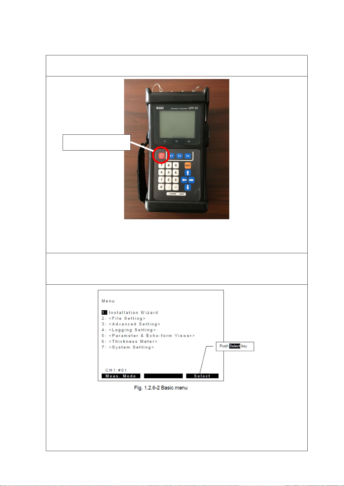
Turn switch on. Then automatically Self Check will be carried out. After the Self Check, select
“OK” <F3>
Select “Installation Wizard” on the basic menu
Select “1: Installation Wizard” by direction or numeric button. Then push “Select” key (F3
button).
Switch on (long
2. Unit Setting
Appendix 1.1-4
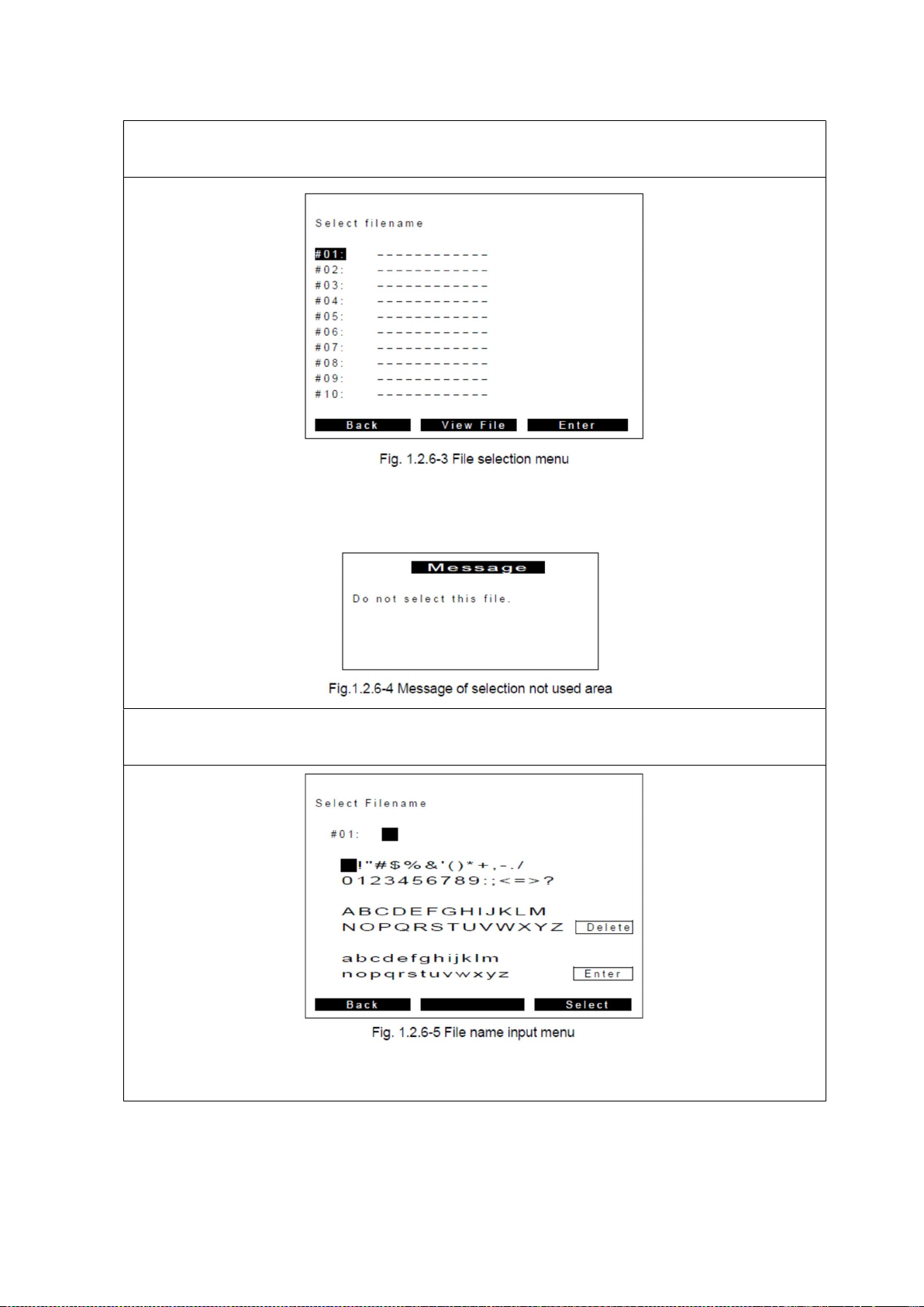
Select file position as “#No.”
Please select Not-Used area by direction button, then push “Enter“ key (F3 button).
Not-used area indicated as “--------” and you cannot select this position. To remove site setting
file, please refer to Chapter 2. When you select used area, you can see the following indication.
File name input
Please input file name by direction button. Here for example, let’s input as “100/Steel/1M”.
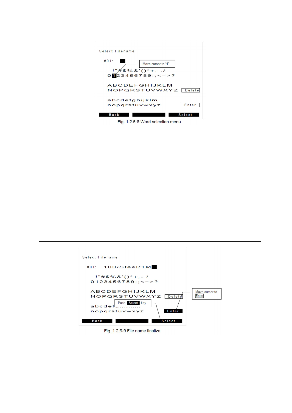
Move cursor to “1” (for example) by direction button. and push “Select” key (F3 button) to
select character. You can see that “1” would set first position as below.
2. Unit Setting
Appendix 1.1-5
Finalizing file name
By repeating procedure of 1-4, you can input “100/Carbon Steel/1M” as follows. After finalizing
the file name, proceed next menu by moving the cursor to “Enter” and push “Select” key (F3
button), otherwise [SHIFT] + F3 button makes the same step taken.
2. Unit Setting
Appendix 1.1-6
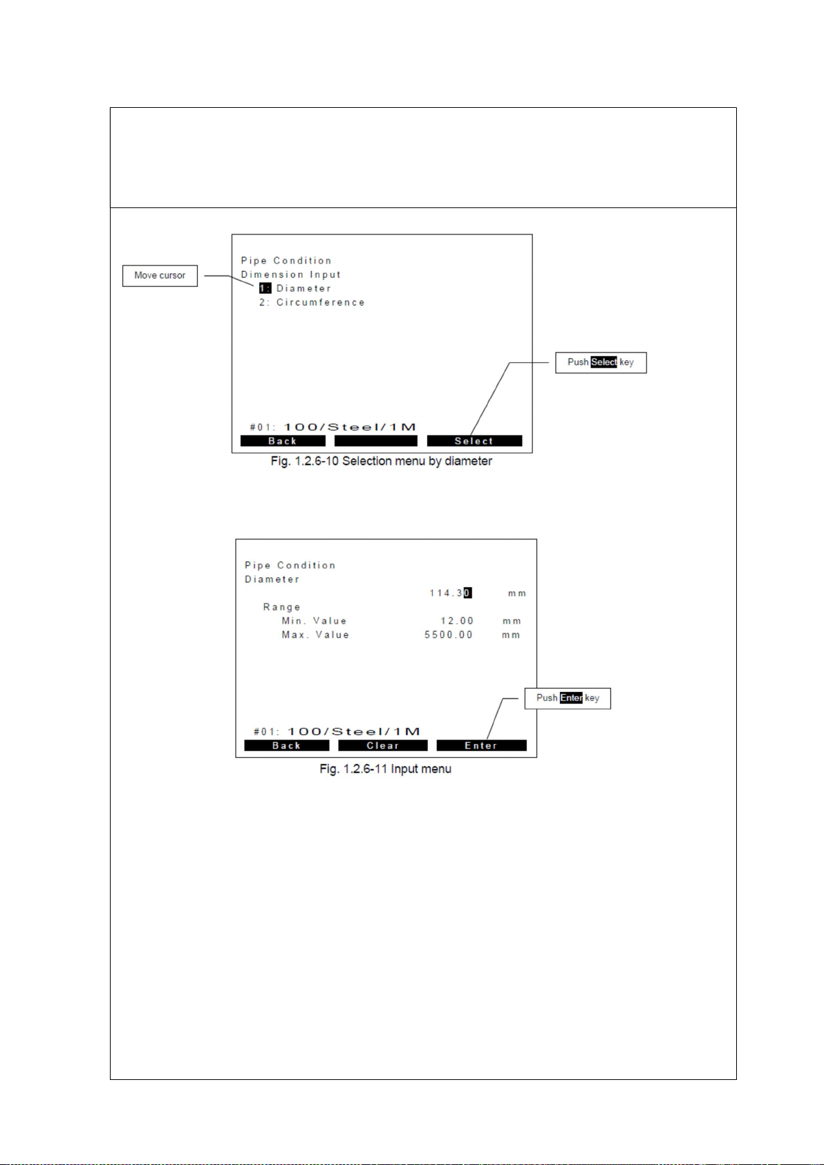
Pipe size setting
Input pipe diameter-by-diameter itself or circumference of pipe. You can select which way you
want by direction or numeric button. Here for example, select “1: Diameter” by push “Select”
key (F3 button). Note: diameter should be OUTER diameter. Please refer to
Input diameter by numeric button directly. Here for example, input 114.30mm as right. Then
push “Enter” key (F3 button) to proceed to next step.

2. Unit Setting
Appendix 1.1-7
Pipe material
Select material of the pipe from default choices or User Defined by direction or numeric button.
Here for example, select “1: Carbon Steel”, then push “Select” key (F3 button) to proceed next
step.
After you select material, you will see predefined sound speed, normally just proceed to next. If
you would like to select any un-listed materials, please select “User Defined” then enter actual
sound speed of the material at the next extra menu.
Thickness of pipe
Input pipe thickness by numeric button directly. Here for example, input “4.50mm”, then push
“Enter” key (F3 button) to proceed to next step.

2. Unit Setting
Appendix 1.1-8
Lining material
Select material of the lining from default choices or User Defined by direction or numeric
button. Here for example, select “2: Epoxy”, then push “Select” key (F3 button) to proceed next
step.
After you select material, you will see predefined sound speed, normally just proceed to next. If
you would like to select any un-listed materials, please select “User Defined” then enter actual
sound speed of the material later at the next extra menu.
Thickness of lining
Input lining thickness by numeric button directly. Here for example, input “1.00mm”, then push
“Enter” key (F3 button) to proceed to next step.

2. Unit Setting
Appendix 1.1-9
Fluid Selection
Select fluid from default choices or User Defined by direction or numeric button. Here for
example, select “1: Water”, then push “Select” key (F3 button) to proceed next step.
After you select material, you will see predefined sound speed and viscosity, normally just
proceed to next. If you would like to select any un-listed fluid, please select “User Defined” then
enter actual sound speed of the fluid later at the next extra menu.
12. Transducer type
Select transducer type from default choices by direction or numeric button. Here for example,
select “2: UP10AST”, then push “Select” key (F3 button) to proceed to the next step.
2. Unit Setting
Appendix 1.1-10
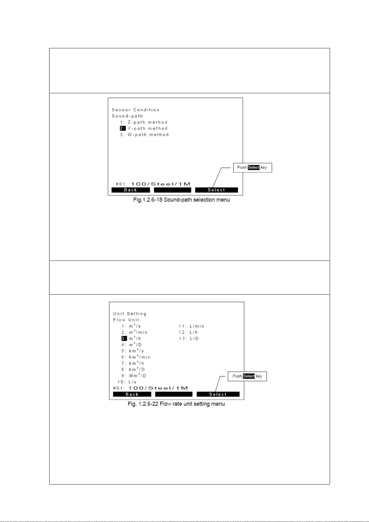
Sound-path selection
Select sound-path method from default choices by direction or numeric button. Here for
example, select “2: V-Path method”, then push “Select” key (F3 button) to proceed to the next
step.
Flow rate unit setting
Select flow rate unit from default choices by direction or numeric button. Here for example,
select “3: m3/h”, then push “Select” key (F3 button) to proceed to the next step.

2. Unit Setting
Appendix 1.1-11
Decimal point position
Select decimal point position from default choices by direction or numeric button. Here for
example, select “***.***”, then push “Select” key (F3 button) to proceed to the next step.
Totalizing unit setting
Select totalizing unit from default choices by direction or numeric button.
Here for example, select “1: ×1m3”, then push “Select” key (F3 button) to proceed to the next
step.
2. Unit Setting
Appendix 1.1-12
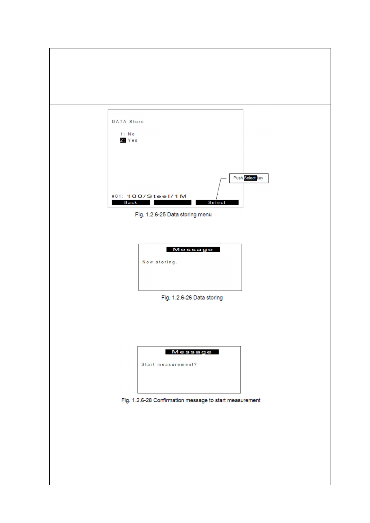
Store site data
Finalize wizard by store all data on this menu. Select “2: Yes” by direction or numeric button.
Then push “Select” key (F3 button) to proceed to the next step.
When select “2: Yes”, following message will be shown.
After storing site-setting data, following confirmation message will show up. Then push “Yes”
(F3 button) to proceed to the next step. Otherwise when you select “No” (F1 button), return to
initial basic menu.
2. Unit Setting
Appendix 1.1-13
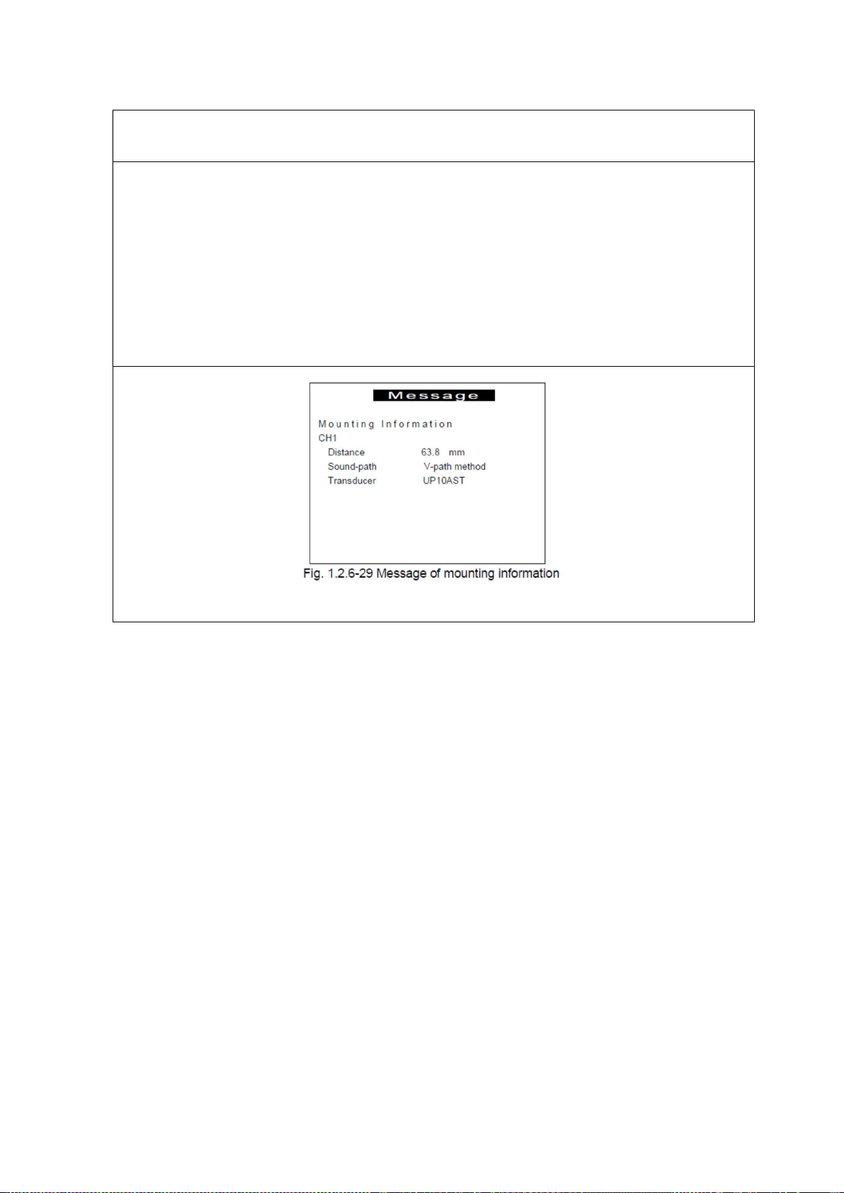
Mounting transducers
The main unit calculates proper distance between transducers as according to the message
appearing below. Then push “OK” (F3 button) to start measurement. Please set transducer
mounting with indicated transducer distance in accordance with instruction on Chapter 1.2.9.
On this example, distance of transducers is 63.8 mm.
Then proceed with Transducer setting.

3. . Transducer Setting
Appendix 1.1-14
3. Transducer Setting
Transducer distance setting
Set distance between transducers on mounting fixture in accordance with the main unit
calculation.
Set mounting fixture onto the pipe
Wrap the mounting chain around the pipe and hook an endo link with the hook knob
arrangement.
Tighten the chain at the other end of the fixture.

3. . Transducer Setting
Appendix 1.1-15
Add coupslant and set transducers to mounting fixture
Add silicone grease as acoustic couplant onto surface of tranceducers.
Then set them into mounting fixture.
Set cables with the transducers and the main unit
Connect cables with the transducers to the main unit
Let’s start measurement
Complete prepartion for measurement. Push OK key as Fig. 1.2.9-9 to start measurement
(mounting information menu)

3. . Transducer Setting
Appendix 1.1-16
Measurement for over DN200mm pipe
In case of measurement for over DN200mm, you need to use mounting fixture 1 and 2 for
extension together as below. The distance between fixtures is 100mm.
When the transducer distance is 245mm(DN300mm), if Up side slide sets t 200mm point,
Down side slide must be set at 125mm point. The point of scale is just a sample. Whenever
transducer distance can be kept, scale point does not matter.

4. Start and Stop Logging
Appendix 1.1-17
4. Start and Stop Logging
Continue from the last step of [2. Unit setting]
Select “OK”<F3>
Select “Log Start”<F1>, and then start logging.

4. Start and Stop Logging
Appendix 1.1-18
Select “Log Stop”<F1> when you want to stop logging.
5. Downloading Logs
Appendix 1.1-19
5. Downloading Logs
When you have stopped logging, select “MENU”<F3>.
Select “Logging Setting” from the menu list<F3>.
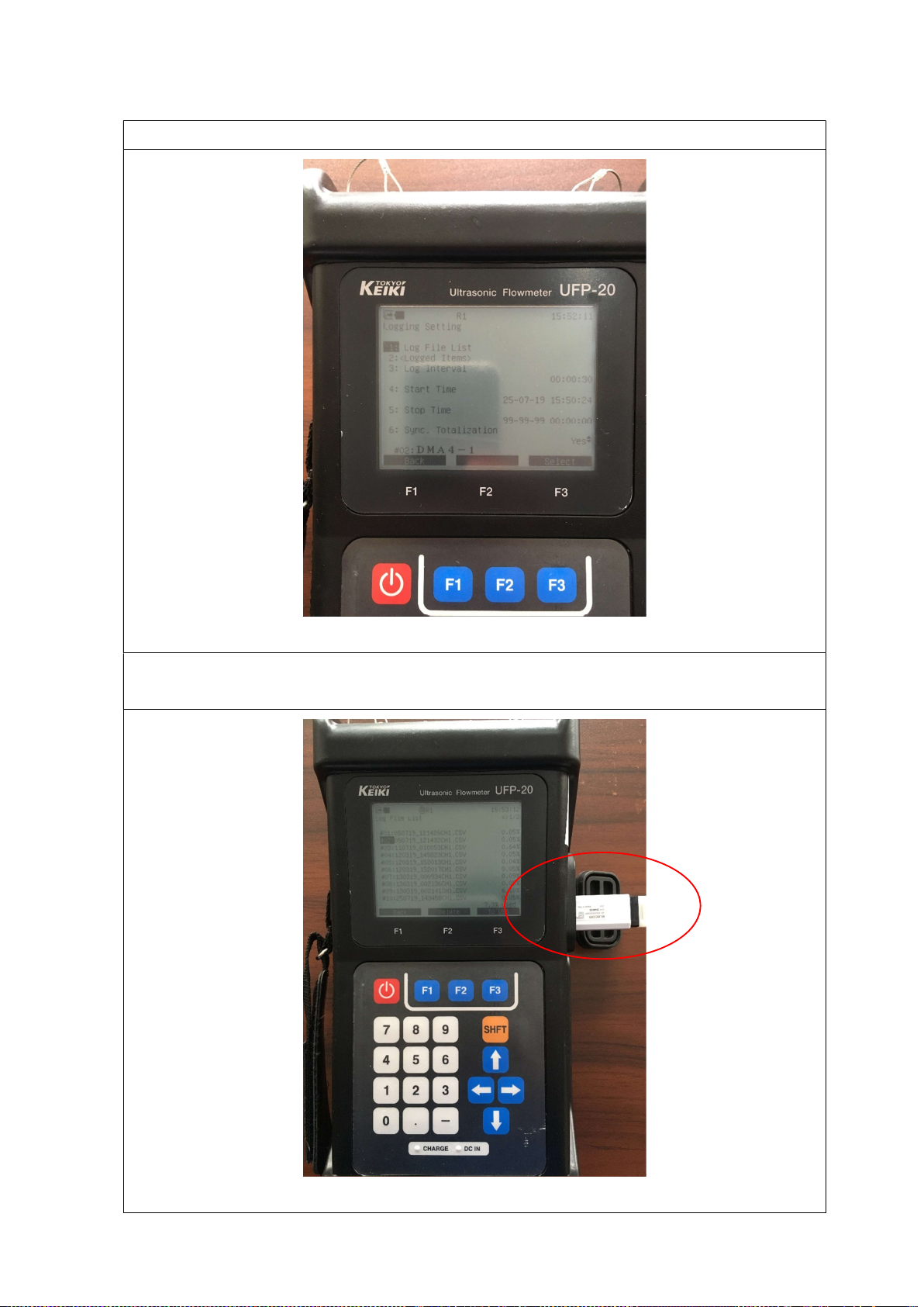
5. Downloading Logs
Appendix 1.1-20
Select “1 : Log File List”
The logging filename is defined automatically. [ DDMMYY.csv ]
Connect a pen drive to the unit.
Other manuals for UFP-20
1
Other Tokyo Keiki Measuring Instrument manuals


