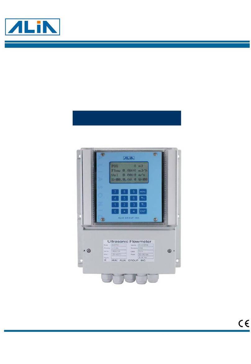
Alia ALIAVTX AVF7000 Series User manual

AVF7000 Operation Manual OP7000.1.1.7.R12ENG
1
Vortex Flowmeter
AVF7000 Series
Operation Manual
ALIA TECHNOLOGY LLC URL: http://www.alia-inc.com
TEL : +1 - 213 - 533 - 4139 FAX : +1 - 213 - 223 - 2317 OP7000.1.1.7.R12ENG
ALIAVTX
®

AVF7000 Operation Manual OP7000.1.1.7.R12ENG
2
Index
1. Flowmeter Check --------------------------------------------------------------------------------------------------------------------3
2. Product Overview --------------------------------------------------------------------------------------------------------------------3
3. Working Principle --------------------------------------------------------------------------------------------------------------------3
4. Specifications -------------------------------------------------------------------------------------------------------------------------4
5. Dimensions ----------------------------------------------------------------------------------------------------------------------------5
6. Installation------------------------------------------------------------------------------------------------------------------------------6
7. Wiring Diagram -----------------------------------------------------------------------------------------------------------------------8
7.1 With 4-20mA(2 wire) or Scale pulse,but without Temp./ Pressure Compensation--------------------------8
7.2 With RS485 Communication,but without Temp./ Pressure Compensation -----------------------------------8
7.3 With Temp./ Pressure Compensation,and 4-20mA(2 wire) or Scale pulse output--------------------------9
7.4 With Temp./ Pressure Compensation,and RS485 Communication-------------------------------------------10
7.5 Separation board-----------------------------------------------------------------------------------------------------------11
8. Panel Display------------------------------------------------------------------------------------------------------------------------12
9. Function ------------------------------------------------------------------------------------------------------------------------------12
9.1 Button Function-------------------------------------------------------------------------------------------------------------12
9.2 Display Function -----------------------------------------------------------------------------------------------------------12
9.3 Field Application------------------------------------------------------------------------------------------------------------13
10. Parameter Operation Chart----------------------------------------------------------------------------------------------------14
11. Parameter Settings --------------------------------------------------------------------------------------------------------------17
11.1 Basic Settings-------------------------------------------------------------------------------------------------------------17
11.2 Advanced Parameter Settings----------------------------------------------------------------------------------------20
11.3 Output 4-20mA Current Calibration----------------------------------------------------------------------------------21
11.4 5 Points linear Calibration -------------------------------------------------------------------------------------------22
11.5 Amplification Gain Settings--------------------------------------------------------------------------------------------23
11.6 Temperature / Pressure Calibration---------------------------------------------------------------------------------23
12. Modbus Communication Settings--------------------------------------------------------------------------------------------25
13. Commonly Seen Problems ----------------------------------------------------------------------------------------------------26

AVF7000 Operation Manual OP7000.1.1.7.R12ENG
3
1. Flowmeter Check
A. Check the overwrap first, if any damages occur, contact ALIA Customer Service Center at once.
B. Confirm whether the instrument has been damaged or its spares are lost.
C. It’s recommended that you read the manual thoroughly, once you have any quires, please email or fax to ALIA
technical department.
D. Ensure all the specifications of instrument are in a normal state.
E. Power on to check whether the LCD screen operates normal.
F. Proper installation is required.
G. Install flowmeter and pipeline under installation instructions.
H. Connect wires and specially attention on whether they have been shielded or grounded.
I. Power on and check whether there is any current leakage (mind your own safety), then if it doesn’t display any flow
rate, please follow steps above again, particularly wiring, power supply and grounding. If problem remains, please
contact ALIA Technical Support center or local agency.
2. Product Overview
Based on Von Karman vortices theory, AVF7000 can be used to measure liquid, gas and steam, even liquid that has
slight particles inside or turbid liquid. It’s widely used in industries such as petroleum, chemical engineering, pharmacy,
paper making, metallurgy, electricity, environmental protection and food.
3. Working Principle
ALIA AVF7000 is newly stress-type flowmeter that’s based on von Karman effect. It’s made up of a whole body whose
internal diameter and nominal diameter are the same and a triangular bluff body inside. Flow will alternately generate
vortices when passing by a bluff body. The periodic shedding of eddies occurs first from one side and then from the
other side of a bluff body (vortex-shedding body), is called "Karman vortex street” whose frequency is proportional to the
flow velocity.
Vortices at both sides cause pressure pulsation, making probe to generate alternation stress. The built-in electronic in
probe generates electric charge due to alternation press. And amplifier transmits them into pulsating output signals
which are equivalent to vortex shedding frequency.
Sensor
d
F=St v/d
F—frequency of vortex shedding (numbers) hz
d—width of bluff body
v—fluid velocity
St—Strouhal number, dimensionless
The actual width of a bluff body within a specific vortex meter is fixed and a function of Reynolds, therefore, a constant.
In linear range, from detected frequency F, pipe’s velocity is known, then volumetric flow. The relationship between
frequency and volumetric flow is defined as below:
Q=3600 F/K
K: factor
F: frequency
Q: fluid volume under actual condition (m3/h)

AVF7000 Operation Manual OP7000.1.1.7.R12ENG
4
4. Specifications
Size (mm) : 15, 20, 25, 32, 40, 65, 80, 100, 125, 150, Protection Class : IP 65.
200, 250, 300, 350, 400, 450, 500 mm Explosion Proof Exd IIC T6
Measuring Range : Steam - 1.6 to 540,000 Kg/Hr Intrinsically safe Exia IIC T4
Gas - 3 to4 6,000 m3/Hr Local Display : 2 or 3 Line LCD
Liquid - 0.3 to 4950 m3/Hr 6 digit Flowrate
Material : Stainless Steel 304 / 316 8 digit Totalizer
Accuracy
Output : 4~20 mA (2wire)
Liquid : +/- 0.7% Load : Rohm=(Vdc-12)*30
Gas/Steam : +/- 1.0% Pulse Output : Standard Pulse Output
Repeatability : +/- 0.2% Load : 1000 000 .
Process Connection : Flange / Wafer Communication : HART or RS485
Flange Type : JIS 10K / JIS 20K / JIS 40K Data Storage : Operation Parameter, Totalizer Figures
are stored by EEPROM.
ANSI 150# / ANSI 300# / ANSI 600# Housing Material : Aluminum Alloy
DIN PN 10 / PN 16 / PN25 / PN 40 Cable Entry : 2x0.5mm2
Wafer Type : 40, 65, 80, 100, 125, 150, 200, 250 Power Supply : 12~32 VDC
without Temperature / Pressure Sensor Keypad : 3 keys from internal for programming and
display control
Temperature :
-40 ~ +280℃ ( Standard Type) Option
-4 ~ +420 ℃(Explosion Proof Type) Pressure Transmitter Pressure Compensation
Ambient Temperature : -20 ~+60℃Signal Input 0~30 mV DC
Pressure : 78 Kg/cm2 (Max.) Temperature Sensor Temperature Compensation
Signal Input PT1000(2 Wire)

AVF7000 Operation Manual OP7000.1.1.7.R12ENG
5
5. Dimensions
mm Inch H1 H2 H3 H4 H5 L1 L2 L3 L4 D1
15 1/2" 430 200
20 3/4" 435 200
25 1" 440 455 440 200 275 275
32 1-1/4" 452 468 452 200 275 275
40 1-1/2" 415 468 477 505 468 70 200 275 275 85
50 2" 425 480 484 518 480 70 200 275 275 99
65 2-1/2" 440 502 495 535 502 70 200 275 275 118
80 3" 460 515 519 550 515 70 225 300 300 132
100 4" 480 534 543 571 534 70 250 350 350 156
125 5" 500 564 560 599 564 70 275 375 375 184
150 6" 530 593 585 631 593 70 300 400 400 211
200 8" 578 647 635 682 647 98 350 450 450 248
250 10" 628 700 685 735 700 114 400 500 500 298
300 12" 750 785 750 450 550 550
350 14" 805 840 805 500 600 600
400 16" 861 895 861 550 650 650
450 18" 910 945 910 600 700 700
500 20" 965 998 965 650 750 750
Wafer Type Flange Type Flange Type
Under Pressure Replace Sensor
Flange Type with T/P Sensor Reduced Bore Type Separate Flange Type
Under Pressure Replace Sensor
Reduced Bore Type
With Temperature Sensor and Pressure Sensor
Normal Size
Note: L5= reduced L4 + pipe diameter before reducing (Example:DN200mm reduce DN150mm , L5 = 400mm + 200mm = 600m
m
Wafer Tpye
15 2
m3 h
.
/
112 7
m3
.
D1
H1
L1
SET
>
>
Q
E
15 2
m3 h
.
/
112 7
m3
.
H3
L
1
D1
SET
>
>
Q
E
15 2
m3 h
.
/
112 7
m3
.
H2
L
2
SET
>
>
Q
E
15 2
m3 h
.
/
112 7
m3
.
H4
L2
SET
>
>
Q
E
15 2
m3 h
.
/
112 7
m3
.
H2
L3
SET
>
>
Q
E
15 2
m3 h
.
/
112 7
m3
.
H5
L4
SET
>
>
E
Q
SET
>
>
15 2
m3 h
.
/
112 7
m3
.
H2
L2
Q
E
15 2
m3 h
.
/
112 7
m3
.
H5
L5
SET
>
>
E
Q

AVF7000 Operation Manual OP7000.1.1.7.R12ENG
6
6. Installation
Installation position of Vortex Flowmeter is very important. It concerns measuring accuracy. Please leave more space of
straight pipe in upstream and downstream as best as you can. If not permitted, please install as 2/3 of total straight pipe
length on the upstream and 1/3 on downstream. However, accuracy this time can not be assured as factory accuracy.
For example:
20D 5D
20D 5D
50D 5D

AVF7000 Operation Manual OP7000.1.1.7.R12ENG
7
18D 5D
18D 5D
● Grounding
Good grounding is highly demanded so as to avoid signal interference. Please see below pictures, all you need to do is
to ground the displayer. And the sensor grounding is unnecessary. Grounding place is like stairs and railing.
To define whether vortex is well grounded initially, user need to check whether frequency is 50HZ or 60HZ or not. If it’s
always 50HZ or 60HZ, it means grounding is poor. Please see details in 9.2 to check frequency value.

AVF7000 Operation Manual OP7000.1.1.7.R12ENG
8
7. Wiring Diagram
Cable should be equipped as 2-core AVPV2*0.5mm2 or 3-core AVPV3*0.5mm2. Connecting terminals should be firm
and tight. Meanwhile, shielding cable must be properly connected to the housing of amplifier.
7.1 With 4-20mA(2 wire) or Scale pulse,but without Temp./ Pressure Compensation
4-20mA (2 wire) output 4-20mA and Scale Pulse
Output
7.2 With RS485 Communication,but without Temp./ Pressure Compensation
12-36VDC Power supply RS485 communication
+-
A
12 32 VDC
-
Power Supply Pulse
Output
15kohm-
mA
A
12 32 VDC-
Power Supply
mA
420mA2wire-( )
A
+-A
I+I-
A+
A-
B
Io
A B
RS485
+
RS485
-
12 32 VDC
-
Power Supply
AB

AVF7000 Operation Manual OP7000.1.1.7.R12ENG
9
7.3 With Temp./ Pressure Compensation,and 4-20mA(2 wire) or Scale pulse output
Sensor Input
4-20 mA Output Pulse Output Temperature Pressure
+
mA
+-
12 32VDC-
Power Supply
+
-
-
A
420mA2wire-( )
+-
+-
12 32VDC
-
Power Supply
15KOhm
~
Pulse
Output
A
T+T-
VV
I+I-A+A-
Current
Outout
+-
Voltage
Input
+-
PT1000
Pressure Sensor
4 Wire
4-20mA and Scale Pulse Output
+-
A
I+
I-A+
A-
12 32 VDC
-
Power Supply Pulse
Output
15kohm
-
mA
A

AVF7000 Operation Manual OP7000.1.1.7.R12ENG
10
7.4 With Temp./ Pressure Compensation,and RS485 Communication
Sensor Input
12-32 VDC Power supply RS485 Communication Temperature Pressure
+
+
-
12 32VDC-
Power Supply
-
AB
+ -
A B
RS485 +RS485 -
T+T-
VV
I+I-A+A-
Current
Outout
+-
Voltage
Input
+-
PT1000
Pressure Sensor
4 Wire
+-A
I+I-
A+
A-
B
Io

AVF7000 Operation Manual OP7000.1.1.7.R12ENG
11
7.5 Separation board
Note: The terminals S1+, S2+ are signal ports of vortex sensor.
Terminal Cable color Sensor
PI+ red
PI- blue
PV+ black
PV- yellow
Pressure sensor
T+ white
TA- red
TB- red
Temperature sensor
S1+ orange
S2+ orange Vortex sensor
PI+
PI-
PV+
PV-
TA-
T+
TB-
S1+
S2+
PI+
PI-
PV+
PV-
TA-
T+
TB-
S1+
S2+

AVF7000 Operation Manual OP7000.1.1.7.R12ENG
12
8. Panel Display
9. Function
9.1 Button Function
Key Button Function
Setting
SETSET
Press shortly (1s) to enter menu settings or exit settings.
Move Press shortly (1s) to shift to page down or move digit position when set parameters.
Up Press shortly (1s) to shift to page up or increase value by “1” when set parameters.
Press long for 3s to enter chosen menu settings or confirm.
9.2 Display Function
In normal display interface, press shortly (3s) and check frequency, density, pressure, temperature, current
percentage …as below:
Symbol F: Den: P: T: Curr: Per: P&T
Content Frequency Density Pressure Temperature Current Percentage
Temperature
Pressure
Other display:
If enable pressure auto acquisition and pressure signal is abnormal, the pressure value in “Temp.&Pressure”
interface will flash.
If enable temperature auto acquisition and temperature signal is abnormal, the temperature value in
“Temp.&Pressure” interface will flash.
.P and T Shows the preset pressure and temperature of circuit board , P&T Shows the pressure and temperature
value from sensor
10.5 m3/h
E 20.0 m3
10.5 m3/h
E 20.0 m3
P=12.5Kpa T=20.0℃
2_Line Display Mode
LCD only displays flow rate and totalizer.
3_Line Display Mode
LCD displays flow rate and totalizer + frequency / density / pressure / temperature / current
/percentage/ P&T.
Press button to choose pressure, temperature, density, current and percentage……
10 3m3 h
.
/

AVF7000 Operation Manual OP7000.1.1.7.R12ENG
13
9.3 Field Application
Two situations will frequently happen at site:
A. No flow, it displays value.
B. Flow, it displays zero.
Reasons for problem A: vortex get interfered by outside environment, keeping receiving interference signals. In the
picture below, interference signal is more than vortex’s threshold value. So vortex displays value. To solve this problem,
interference signal should be smaller than threshold value.
V
The Threshold
Interfering Signa
l
Reasons for problem B: flow frequency is very low, see the flow signal below. It’s lower than threshold value, leading
to measurement failure. To solve this problem, flow signal should be bigger than threshold value.
V
Flow Signal
The Threshold
Then how to adjust interference signal and flow signal?
The solution lies in signal amplification. Signal amplification adjustment is ”2000~2000000”.
Default amplification:
If measuring medium is liquid, it’s 5000.
If measuring medium is gas or steam, it’s 80000.
Amplification adjustment method:
☆ Magnification can be divined into two parts:
amplification factor and magnification gain.
Magnification factor is in “Max AMP”while magnification gain in “AMP. Channel”.
If amplification is 5000, amplification factor will be 500 and amplification gain 101 , namely 500*101 =5000.
Amplification factor Amplification gain
(Range: 200~2000) (CH1=101; CH2=102; CH3=103 )
☆To solve problem A: decrease amplification factor. Suppose amplification is 5000 now, change amplification factor
(Max AMP) as 400 but keep amplification gain (AMP.Channel) the same (CH1). Then amplification is 400*101 =4000. If
vortex still displays unusually, adjust amplification factor again.
☆To solve problem B: it happens to be on the contrary of A, namely adjust amplification from 5000 to 30000. Then:
Change amplification factor (Max AMP) as 300;
Change amplification gain (AMP. Channel) as CH2;
Amplification number is: 300*102 =30000
☆In conclusion, amplification has to be set according to actual condition, making vortex displays properly, namely it
displays zero when there is no flow and displays correct values when there is flow.
Max AMP
500
AMP.Channel
CH1

AVF7000 Operation Manual OP7000.1.1.7.R12ENG
14
10. Parameter Operation Chart
SETSET
Contrast
Protection
Meter Size
Flow Mode
Unit
Range 100%
Density(Kg/m3)
Gauge Pre(Kpa)
PV Cutoff (%)
Damping(S)
Min Alarm(%)
Max Alarm(%)
SETSET
10.5 m3/h
E 20.0 m3
P=12.5Kpa T=20.0℃
Disp.Point
Temperature(℃)
CODE
K-Factor
Display Mode
Total Rest
Total Overflow

AVF7000 Operation Manual OP7000.1.1.7.R12ENG
15
Fluid Type
Low Flow Limit
Password ## Password ##
Si
g
nal Monito
r
High Flow Limit
CODE
+
Mete
r
Size
Max AMP.
K-Factor
Password ## Password ##
Pulse Factor Unit
Pulse Factor
SETSET
CODE
SETSET
4mA Trim
20mA Trim
CODE
SETSET
SET
SET
K-Factor Trim Y1
K-Factor Trim F1
K-Factor Trim Y2
K-Factor Trim F2
K-Factor Trim Y3
K-Factor Trim F3
K-Factor Trim Y4
K-Factor Trim F4
K-Factor Trim Y5
K-Factor Trim F5
Frequency Factor
CODE
SETSET
SETSET
CODE
SETSET
SET
SET
10.5 m3/h
E 20.0 m3
P=12.5Kpa T=20.0℃

AVF7000 Operation Manual OP7000.1.1.7.R12ENG
16
Password ##
CODE
+
Password ##
Password ##
Password ##
AMP. Channel
CODE
SETSET
SET
SET
Work Mode
CODE
SETSET
SET
SET
Temp. Low Trim
Temp. High Trim
Tem
p
. Measure
Pre. Low Trim
Pressure Measure
Pre. High Trim
Pre. Cutoff
Set Pre. Bias
Modbus Addr
Modbus Baud
CODE
SETSET
SET
SET
CODE
SETSET
10.5 m3/h
E 20.0 m3
P=12.5Kpa T=20.0℃
SETSET

AVF7000 Operation Manual OP7000.1.1.7.R12ENG
17
11. Parameter Settings
11.1 Basic Settings
10.5 m3/h
E 20.0 m3
Normal Display
This interface shows flow rate and totalizer.
Press
SETSET
to enter next setting interface.
Contrast
Set the contrast, 1-5 are optional. The larger the number, the deeper the font color(default is 3). Set
by and keys.
Press to enter next setting interface.
SETSET
Contrast
4
Parameter Lock
Parameter settings are protected and locked. Press long to shift in Enable / Disable. If Disable,
all parameters can not be edited but can be checked only.
Press to enter next setting interface.
Protection
Weite Enable
Alarm Low Limit
Set by and keys, for instance, -100%, it means alarm low limit is -100%*Full scale. If
displayed value is less than the low limit, the current output is 3.8mA. (This function is only effective
for 4-20mA output.)
Max Alarm(%)
200.000
Min Alarm(%)
-100.000
Alarm High Limit
Set by and keys, for instance, 200%, it means alarm high limit is 200%*Full scale. If displayed
value is more than the high limit, the current output is 22mA. (This function is only effective for 4-
20mA output.)
Meter Size
DN50
Meter Size
Only-read window. Check meter size.
Press to enter next setting interface.
Flow Mode
Set by and keys. Liquid Qv: liquid volume; Liquid Qm: liquid mass; Gas Qv: gas volume;
Gas Qv: gas mass; Steam Qv: steam volume; Steam(P/T):superheated steam
Sat Steam(T): saturated steam mass (temperature compensation); Sat_Steam(P) : saturated steam
mass (pressure compensation).Press to enter next setting interface.
Flow Mode
Gas Qv
Unit
Set by and keys. Nm3/h, Nm3/m, Nm3/s, m3/d, m3/h, m3/m, m3/s, l/h, l/m, l/s, t/d, t/h, t/m,
kg/d, kg/h, kg/m, kg/s, g/h, g/m, g/s, G/h, G/m, G/s, bbl/h, bbl/d, lb/h, lb/d. Flow mode determines
flow unit, it flow mode is different, flow unit will be different. Press to enter next setting interface.
Unit Qv(Unit Qm)
Nm3/h
Range 100 %
90.000
Full Scale
Set by and keys.
Press to enter next setting interface.

AVF7000 Operation Manual OP7000.1.1.7.R12ENG
18
PV Cutoff(%)
0.00
Damping(S)
1.0
Low Cut
Set by and keys. Available input is 0%~20%.
Press to enter next setting interface.
Damping
Set by and keys. Available time is 0~64s.
Press to enter next setting interface.
Gauge pre.(Kpa)
1000.00
Density(kg/m3)
1.025
Gas Pressure (gauge pressure)
Set by and keys. This is used for inputting pressure (unit: Kpa) manually (in Pressure
Measure window). This value is pressure value for temperature/pressure compensation when it is
on. If measuring liquid, no such option is available. Press to enter next setting interface.
Fluid Density
Set by and keys. Gas density (unit: kg/m3); liquid density (unit: g/cm3)
Press to enter next setting interface.
Total Reset
NO
Totalizer Reset
Set by and keys. Choose YES and then press long to reset totalizer.
Press to enter next setting interface.
Total Overflow
0.000
Totalizer Overrange Cycle
This interface is read only. When flow total is over 99999999, the overrange cycle will be 1. And
then flow total will start accumulating from 0 again.
Press to enter next setting interface.
Gas Temperature (Celsius)
Set by and keys. This is used for inputting temperature (unit ℃) manually (in Temp.Measure
window). This value is temperature value for temperature/pressure compensation when it is on. If
measuring liquid, no such option is available. Press to enter next setting interface.
Temperature(℃)
20.000
Disp. Point
1
Decimal point
Press or to set decimal point, 3 decimal points at most.
Press to enter next setting interface.
Display Mode
3_Line Display
Display Mode
Press or to set display mode.
2_Line Display: LCD only shows flow rate and totalizer.
3_Line Display: LCD shows Flow rate and totalizer+frequency/density/pressure/temperature/current/
percentage /P&T.
Press to enter next setting interface.

AVF7000 Operation Manual OP7000.1.1.7.R12ENG
19
Code
00000
Password
Set by and keys. Enter advanced settings by password. Press to return parameter
protection interface. Press
SETSET
to back to normal display interface.
SETSET
10.5 m3/h
E 20.0 m3
K-Factor
9100.00
K-Factor
Read-only window. Check K-factor.
Press to back to normal display interface.

AVF7000 Operation Manual OP7000.1.1.7.R12ENG
20
11.2 Advanced Parameter Settings
Password
Set by and keys. Enter password 00050 then press long for 3s to enter advanced
parameter settings.
Code
00050
Signal Monitor
450.00
CH 2
+
Signal Monitor
Read-only window.
450.00 is the current magnification.
CH 2 is the current channel number.
Size
Set by and keys. DN50 on LCD means that size is 50mm。
If change vortex size, lower limit flow, max. magnification and K-factor are need to be reset.
Press to enter next setting interface.
Meter Size
DN50
Fluid Type
Set by and keys. Options: Gas, Liquid。
If change medium, lower limit flow, max. magnification and K-factor are need to be reset.
Press to enter next setting interface.
Fluid Type
Gas
High Flow Limit
Set by and keys. Theoretical max. flow rate, this parameter does not affect the measurement,
for reference only. Do not change it (if necessary, please contact ALIA).
Press to enter next setting interface.
Low Flow Limit
35.000m3/h
Low Flow Limit
Set by and keys. Theoretical min. flow rate, this parameter does not affect the measurement,
for reference only. Do not change it (if necessary, please contact ALIA).
Press to enter next setting interface.
High Flow Limit
350.000m3/h
Amplification factor
Set by and keys. What amplification factor corresponds to is the amplification factor of vortex
signal. Setting range: 0-2000, recommended range: 200-2000 (For air, standard default value is
800; liquid: 500) It can be adjusted by signal strength in Signal Monitor. It’s not recommended to
change Max.AMP. If necessary please contact ALIA engineer.
Press to enter next setting interface.
Max. AMP
500
K Factor (Pulse/m3)
Instrument calibration factor. Do not modify K-Factor, or measurement accuracy will be influenced.
Press to enter next setting interface.
K-Factor
9100.00
Pulse Factor Unit
m3
Unit for Scale Pulse
Set by and keys. Available unit: t, kg, Nm3 and m3.
Press to return to signal strength and
SETSET
to password interface.
Table of contents
Other Alia Measuring Instrument manuals