Tokyo Keiki ESW Series User manual

DocumentNo[TS19‐005]
Total46pages(text,38pages)
ESWSeries
ElectronicPressureSwitch
ESWS‐10
SettingUnit
INSTRUCTIONMANUAL
Toinsuresafetyinproducthandlinganduse,thoroughlyreadthecontents
ofthisinstructionmanual. Keepthisinstructionmanualinahandyplace
foreasyreferral.
FluidPower&ControlSystemsCo.

SafetyPrecautions [TS19‐005]
(
i
)
SafetyPrecautions
Thesafetyprecautionsdescribedinthismanualshouldbestrictly observedinorder toinsuresafeand correctuseof the
product.
SafetyConventions
WARNING
Indicates a potentially hazardous situation which, if not avoided, may result in death or
seriousinjury.
CAUTION
Indicates a potentially hazardous situation which, if not avoided, may result in personal
injuryorpropertydamage.
GeneralHandling
WARNING
Products are precision electronic devices. Do not attempt to disassemble or modify them as damage,
malfunctionorotherproblemscouldresult.
Immediatelystopoperationandtheturnpoweroffiftheproductsemitsmoke,strangeodor,orunusualnoise
orwhensomeotherabnormalordangerousconditionisdetected.Continuedusemayleadtosystem(hydraulic
equipment,mechanicalequipment)malfunction,fireorotherseriousaccidents.
Do not subject pressure switch to pressures beyond rated pressure. Excessive pressures could damage or
breakthepressureelementandcauseinjuryand/ordestructionofsurroundings.
Usingunspecifiedvoltagecouldcausefiresorelectricalshock.
Donotsubjectproductstoexcessiveweight,vibrationorimpactthatcoulddamageorbreakproducts,cause
leakageofmeasurementmediumthatcanleadtoinjuryordamagetothesurroundings.
Products are not explosion‐proof. Do not use in hazardous areas where flammable or explosive gases or
liquidsmaybepresent.
Performwiringcorrectlyaccordingtothewiringdiagramintheinstructionmanual. Incorrectwiringcanresult
inproductfailureorfire.
Usewithinoperatingtemperaturerange. Useofproductsoutsidetheoperatingtemperaturerangecanlead
toproductfailureandcauseinjuryaswellasdamagetothesurroundings.
Carryoutinstallationinaccordancewiththeinstructionmanual.
Theseprecisionelectronicdevicesshouldbekeptawayfromsourcesofelectricalnoise. Usenoisefilters,etc.,
toreduceelectricalnoisefromthepowersourcestotheseproducts.

SafetyPrecautions [TS19‐005]
(
ii
)
Installation
WARNING
Donotattempttochangewiringorinsertordisconnecttheconnectorwhiletheproductsareenergizedasit
couldleadtoseriousaccidents.
CAUTION
When installing the pressure switch ina pressure line, do not install itwhile the lineisfilled with liquid. As
liquid is incompressible, tightening the pressure fitting could generate high pressures that could damage the
pressureswitch. Wheninstallingthepressureswitch,removeliquidfromthepressureline,leavingabout15to
20mmofairandthentightenthepressurefitting.
Donotinsertwiresorothersharpobjectsintothepressureinletastheycoulddamagethediaphragmandaffect
normaloperationofthepressureswitch.
Connections
WARNING
Donotattempttochangewiringorinsertordisconnecttheconnectorwhiletheproductsareenergizedasit
couldleadtoseriousaccidents.
Operation
WARNING
Ifthesettingunitistoberecharged,usenickelhydride(NiMH)batteriesonly.UsingbatteriesotherthanNiMH
batteriesmaycauseseriousaccidents.
Storage
CAUTION
Donotstoreinthefollowinglocationsthatcouldcauseproductfailureordamage.
Locationsthatexposeproductstowater.
Locationswithatmosphericpressure,temperature,humidity,ventilation,sunlight,dust,salt,aircontainingsulfur,
etc.,conditionsthatcouldadverselyeffecttheproducts.
Locationsthataresubjecttovibrationandshock(includingduringtransport).
Locationswherechemicalsarestoredandplaceswheregasisgenerated.
Locationsexposedtodirectsunlight,hightemperaturesinsidevehicles,etc.

UsingthisManual [TS19‐005]
(
iii
)
UsingthisManual
Aboutthismanual
ThismanualprovidesinstructionontheoperationandhandlingoftheESWSerieselectronicpressureswitch
andESWSsettingunit.Thismanualshouldbethoroughlyreadandunderstoodinordertoinsurethatoperation
andhandlingisdonecorrectly.
Thismanualisintendedfortechnicalpersonnelwithbackgroundsinmechanical,electrical,orcontrol
engineering.
Personnelwhohandlethisproductarerequiredtohaveknowledgeandbackgroundsinelectrical,electronics,
hydraulics,andautomaticcontroltechnology.
Pointstoobserve
Thefollowingpointsshouldbeobservedwithregardtothismanual.
Pleasereadthismanualcarefullyandthoroughly.
Importantinformationiscoveredandthecontentsshouldbefullyunderstood.
Maintainmanualwithcareandkeepmanualclosebyforreadyreference.
Thismanualshouldbeprovidedtothepersonnelwhoactuallyhandletheproduct.Intermediariessuchassales
agents,distributors,orresellersshouldmakesurethatthismanualisprovidedtosuchpersonnel.
Ifthemanualislost,replaceimmediately.Ifyouhavelostthismanual,contactoursalesofficeorservicecenter
andorderareplacement.
Precautionsregardingproductprotection
Pleaseobservethefollowingprecautionstoensureproductprotection.
Performinstallationandwiringinacorrectmanner.
Donotuseproductsunderconditionsorenvironmentthatexceedspecifications.
Donotsubjectproductstoexcessiveweightormanhandling.
Productsareprecisionelectronicdevices. Handlewithcare.

Contents [TS19‐005]
(
iv
)
Contents
SafetyPrecautions...........................................................................................................................................i
UsingthisManual...........................................................................................................................................iii
Aboutthismanual...........................................................................................................................................................iii
Pointstoobserve.............................................................................................................................................................iii
Precautionsregardingproductprotection......................................................................................................................iii
Contents.........................................................................................................................................................iv
FiguresandTables............................................................................................................................................v
1.
Introduction..............................................................................................................................................1
1.1
Overview...............................................................................................................................................................1
1.2
Modelcodes.........................................................................................................................................................1
1.3
Productdescription..............................................................................................................................................2
2.
AppearanceandDimensions.....................................................................................................................3
2.1
Dimensionsandnomenclature.............................................................................................................................3
3.
Specifications............................................................................................................................................5
3.1
Specifications........................................................................................................................................................5
3.2
Factorydefaultsettings........................................................................................................................................7
4.
Functions..................................................................................................................................................8
4.1
PressureSwitchfunctions.....................................................................................................................................9
4.2
SettingUnitfunctions.........................................................................................................................................11
5.
InstallationandConnections...................................................................................................................16
5.1
Installation..........................................................................................................................................................16
5.2
Piping..................................................................................................................................................................16
5.3
Connectionsandwiring......................................................................................................................................17
5.4
Wiringconnectionexamples..............................................................................................................................17
6.
Operation...............................................................................................................................................20
6.1
Flowofoperation...............................................................................................................................................20
6.2
SettingUnitoperation........................................................................................................................................21
6.3
Operation............................................................................................................................................................22
7.
StorageandMaintenance.......................................................................................................................36
8.
Troubleshooting......................................................................................................................................37

Contents [TS19‐005]
(
v
)
FiguresandTables
FIG1PressureSwitch...........................................................................................................................................................3
FIG2SettingUnit..................................................................................................................................................................4
FIG3Operatingtemperatureandoutputcapacityrelationship..........................................................................................5
FIG4Hysteresismodeoperation.......................................................................................................................................10
FIG5Windowcomparatormodeoperation......................................................................................................................10
FIG6Deadbandofsettingpoints(A),(b)...........................................................................................................................11
FIG7Batterylifeindicatoricon..........................................................................................................................................14
FIG8M12connectorpinarrangement..............................................................................................................................17
FIG9NPNopencollector,example1(wiringtorelay)......................................................................................................18
FIG10NPNopencollector,example2(wiringtophotocoupler)......................................................................................18
FIG11NPNopencollector,example3(voltageoutput)....................................................................................................18
FIG12PNPopencollector,example1(wiringtorelay).....................................................................................................19
FIG13PNPopencollector,example2(wiringtophotocoupler)......................................................................................19
FIG14PNPopencollector,example3(voltageoutput)....................................................................................................19
FIG15Settingandmeasurementoperationflowchart.....................................................................................................20
FIG16SettingUnitnomenclature......................................................................................................................................21
FIG17Withrubbercapremoved.......................................................................................................................................23
FIG18SettingUnitbatteryinsertionandturningpowerON.............................................................................................23
FIG19IRextensioncableattachment................................................................................................................................24
FIG20Mainmenutosettingmenuscreendisplayexample.............................................................................................25
FIG21Functionsettingscreenexample.............................................................................................................................25
FIG22COMPARATORsettingscreenexample...................................................................................................................26
FIG23DELAY(ON,OFF)screendisplay..............................................................................................................................27
FIG24SPECIALscreendisplay............................................................................................................................................28
FIG25Stepstocreatenewsettingdata,editingandwritingsaveddata..........................................................................28
FIG26Savesettings............................................................................................................................................................29
FIG27Measurementmodeoperationflowchart..............................................................................................................30
FIG28Measurementmodedisplay....................................................................................................................................31
FIG29Top/bottomhold/loopcheckscreentransition..................................................................................................32
FIG30Infraredcommunicationsettingoperation.............................................................................................................33
FIG31Deviceinformationscreendisplay..........................................................................................................................34
FIG32Endsettingoperation..............................................................................................................................................34
FIG33RechargingSettingUnit...........................................................................................................................................35
TABLE1Productdescription................................................................................................................................................2
TABLE2Generalspecifications.............................................................................................................................................5
TABLE3Enviromentalandstructuralspecifications............................................................................................................6
TABLE4SettingUnitspecifications......................................................................................................................................6
TABLE5PressureSwitchfactorydefaultsettings................................................................................................................7
TABLE6SettingUnitfactorydefaultsettings.......................................................................................................................7
TABLE7PressureSwitchfunctions.......................................................................................................................................8
TABLE8SettingUnitfunctions.............................................................................................................................................8
TABLE9M12connectorterminalfunctions.........................................................................................................................9
TABLE10LEDfunctions........................................................................................................................................................9
TABLE11Functionalsettings...............................................................................................................................................11
TABLE12Comparatorpressuresetting..............................................................................................................................12
TABLE13Keylockfunction.................................................................................................................................................12
TABLE14Measurementfunctions.....................................................................................................................................13
TABLE15SettingUnitconfigurationsettings.....................................................................................................................14

Contents [TS19‐005]
(
vi
)
TABLE16RecommendedtighteningtorqueofSUS304mountingcomponent.................................................................16
TABLE17M12connectorpinfunction...............................................................................................................................17
TABLE18SettingUnitcontrolanddisplayfunctions.........................................................................................................21
TABLE19Listofoperations................................................................................................................................................22
TABLE20Comparatoroperationpressuresettings...........................................................................................................26
TABLE21TroubleshootingPressureSwitch.......................................................................................................................37
TABLE22TroubleshootingSettingUnit..............................................................................................................................38

[TS19‐005]
‐1‐
1.
Introduction
WARNING
Productsareprecisionelectronicdevices.Donotattempttodisassemble or modify products as damage,
malfunctionorotherproblemscouldresult.
1.1
Overview
TheESWSerieselectronicpressureswitch(PressureSwitch)comparesoutputfromasemiconductorpressure
sensorandperformsswitchingfunctions,allelectronically. ThePressureSwitchhasnomovingpartsand
boastsexcellentdurabilityandvibrationcharacteristics.ThededicatedESWSsettingunit(SettingUnit)forthe
ESWSeriesPressureSwitchcheckspressuremeasurementsandsetsdetectionpressureandcontactpoint
output.
1.2
Modelcodes
1.2.1
ESWElectronicPressureSwitch
1.2.2
ESWSSettingUnit

[TS19‐005]
‐2‐
1.3
Productdescription
EachproductisdescribedandreferredtointhismanualasindicatedinTABLE1.
TABLE1Productdescription
Product Description
Electronicpressureswitch(ESWSeries) PressureSwitch
Settingdevice(ESWS‐10)forESWelectronicpressureswitch SettingUnit

[TS19‐005]
‐3‐
2.
AppearanceandDimensions
2.1
Dimensionsandnomenclature
2.1.1
PressureSwitchdimensionsandnomenclature
FIG1PressureSwitch

[TS19‐005]
‐4‐
2.1.2
SettingUnitdimensionsandnomenclature
FIG2SettingUnit

[TS19‐005]
‐5‐
3.
Specifications
3.1
Specifications
3.1.1
PressureSwitchspecifications
TABLE2Generalspecifications
Description Specifications
Pressurerange 0to1MPa,0to10MPa,0to25MPa,0to35MPa,0to50MPa
Absolutemax.pressure
*
1
Doublepressurerange,but1.5timesatpressureranges35MPaorabove
Connectionthread R1/4,G1/4A,G3/8A
Ratedpowersourcevoltage 9to36VDC
Consumptioncurrent Lessthan30mADC(noload)
Outputspecification Opencollectoroutput
Outputcontactpoints 2
Outputcapacity NPN,lessthanDC36V;PNP,powersourcevoltagerange
Outputcapacitymayvarywithoperatingtemperature. SeeFIG3.
Response Lessthan1ms
Repeatability ±0.2%F.S.
Settingaccuracy ±(0.5%F.S.+1count)
Includinglinearity,hysteresis
Settingmethod IRcommunicationtoSettingUnit
*1 Allowablemaximumpressureistheupperlimitofpressurevaluewhichmaysafelybe
appliedtotheproductandremaininspecificationoncepressureisreturnedtothe
ratedpressurerangewithacoupleoftimesoverpressurizationofabout10minutes
duration.Productperformanceatcontinuousoverpressureisnotguaranteed.
FIG3Operatingtemperatureandoutputcapacityrelationship

[TS19‐005]
‐6‐
TABLE3Enviromentalandstructuralspecifications
Description Specifications
Operatingtemperaturerange ‐20to70°C(nofreezing,nocondensation)
Operatinghumidityrange 85%RHorlesswhenpressurerangeforpressurerangelessthan
2MPa(nofreezing,nocondensation)
Storagetemperatureandhumidityrange ‐30to80°C,95%orless(nofreezing,nocondensation)
Withstandvoltage 250VACat1minute,fittingtoinput/outputterminalscollectively
Insulationresistance 100MΩormore(at50VDC),fittingtoinput/outputterminals
collectively
Vibrationresistance 300m/s
2
,10to2,000Hz,JISC60068‐2‐6
Impactresistance 1,000m/s2;6ms;X,Y,Zforwardandreversedirection,3times;
JISC60068‐2‐27
Caseconstruction Indooruse
(Protectionclass:IP67. HoweverIP65at1MPa,JISC0920)
Casematerial SUS304,PESresin
*1
Wettedmaterial
Diaphragm:SUS630
Fitting:SUS304,SUS630(connectionthreadforabove20MPa:G1/4A)
Orifice: S45C
Materialofprotectivecap NBR
Connector M12connector(4P);specialM12connectorcable
Protectioncircuit Reversepolarityprotection,short‐circuit(overcurrent)protection
Weight Approximately100g
*1 Polarsolventsandstrongacidssuchasacetoneandchloroformmaycorrodecase.
Ketoneorestersubstancesmaycausestresscracking.
3.1.2
SettingUnitspecifications
TABLE4SettingUnitspecifications
Description Specifications
Communication Infrared
Range
*1
andangle Lessthan300mm,lessthan±15°
Powersource Two,AAAnickel‐hydrideoralkalinebatteries2
Recharging RechargeablewithUSBconnector(USB2.0,Micro‐B(male))fornickel‐hydridebatteries.
Operatingtemperature 0to40°C(incaseofnickel‐hydridebatteries)
Storagetemperature ‐10to50°C(batteriesremoved)
Protection Indoorspecifications(nonwaterproof)
Casematerial ABSresin
Covermaterial Siliconerubber,blue
Accessories Infraredextensioncable(2m)

[TS19‐005]
‐7‐
3.2
Factorydefaultsettings
TABLE5andTABLE6showthefactorydefaultsettingsofthePressureSwitchandSettingUnitrespectively.
Asoutputpolarity,settingpressureanddeadbanddifferaccordingtothemodel,pleaserefertothereference
drawingordeliveryspecifications.
TABLE5PressureSwitchfactorydefaultsettings
Description Outputspecifications
Outputpolarity Varieswithmodel
Comparatoroperation Hysteresismode
Settingpressure Varieswithmodel
Deadband Varieswithmodel
ON,OFFdelay 0s
Filter None
Keylock Unlock
TABLE6SettingUnitfactorydefaultsettings
Description Construction
IR(infraredcommunication) int(IRextensioncablenotused)
Sleeptime none
Backlight ‐9
Contrast 0

[TS19‐005]
‐8‐
4.
Functions
ThefollowingtableslistthefunctionsofthePressureSwitchandSettingUnit.
TABLE7PressureSwitchfunctions
Function/Mode Description Pagereference
Connector EquippedwithM12(4P)connectors 4.1.1(P.9)
Display DisplaysPressureSwitchoperationstatuswithpowersourceLED/outputLED. 4.1.2(P.9)
Comparator Hysteresisorwindowcomparatoroperation 4.1.3(P.10)
TABLE8SettingUnitfunctions
Function/Mode Description Pagereference
Search
(SEARCH) Acquireserialno.ofPressureSwitchtobeset 4.2.1(P.11)
Setting
(SETTING)
Pressure,deadband 4.2.2
1)(P.11)
ComparatorON/OFFdelaysetting 4.2.22)(P.12)
Outputpolarity
4.2.23)(P.12)
Comparatoroperationmode
Filter
Specialfunction
(IRcommunicationLOCK/UNLOCK) 4.2.24)(P.12)
Measurement
(MEASURE)
Pressure 4.2.31)(P.13)
Changesettingpressure 4.2.32)(P.13)
Zeropointadjustment 4.2.33)(P.13)
Peakhold 4.2.34)(P.13)
Loopcheck 4.2.35)(P.13)
Memory
(MEMORY)
Createmeasurementdata(max.12data),
save,copy 4.2.4(P.14)
Configuration
(CONFIG)
IRcommunicationcableextensionused/notused
4.2.5(P.14)
Timeuntilsleepmode
LCDbacklight/contrast
Deviceinformationdisplay
(About...) BatteryvoltageandSettingUnitsoftwareversiondisplay 4.2.6(P.14)
Batterylifeindicator Remainingbatterylifeicon 4.2.7(P.14)
Recharging RechargeSettingUnit(fornickel‐hydridebatteries)4.2.8(P.15)

[TS19‐005]
‐9‐
4.1
PressureSwitchfunctions
4.1.1
Connectorfunctions
ThePressureSwitchincorporatesanM12(4pole)connectorforinput/output. Thepinarrangementand
terminalfunctionsoftheM12connectoraredescribedinTABLE9.
TABLE9M12connectorterminalfunctions
Pinlayout Terminal
no. Description Function
1 Powersource+ +Powerinput
Outputcommon(NPN)
2 Output2(OUT2) Opencollector
3 Powersource– –Powerinput
Outputcommon(PNP)
4 Output1(OUT1) Opencollector
4.1.2
Displayfunction
TheoperationalstatusofthePressureSwitchcanbecheckedbytheLEDsonthePressureSwitch,byconfirming
thecoloroftheLEDandwhetheritisONorOFF. FunctionsofeachLEDarelistedinTABLE10.
TABLE10LEDfunctions
LEDlayout Description Function
PowerLED
NPNsetting Lightsblue
PNPsetting Lightsgreen
IRtransceiving Flasheswhite
OutputLED
OUT1
OUT1,ON Lightsred
OUT1,OFF Lightoff
OutputLED
OUT2
OUT2,ON Lightsred
OUT2,OFF Lightoff

[TS19‐005]
‐10‐
4.1.3
Comparatorfunction
ThecomparatorfunctioncomparesthepressurethatisappliedtothestainlesssteeldiaphragmofthePressure
SwitchagainstadeterminationpressurevaluethatissetinthePressureSwitchtoturnitONorOFF. Two
comparatoroperatingmodes‐hysteresismodeandwindowcomparatormode‐canbeselected. Usethe
SettingUnittosetthecomparatoroperatingmode.
Hysteresismodeoperation
IntheHysteresismodethesettingpressurecanbesetastheupperlimitorlowerlimit,dependingonthe
deadbandsetting.
“Upperlimitsetting”
Whenyouselectapositivenumber(including0)forthedeadband(
⊿
P
)
,thecomparatorwilloperatewiththe
settingpressure(P)astheupperlimit.
“Lowerlimitsetting”
Whenyouselectanegativenumberforthedeadband(
⊿
P
)
,thecomparatorwilloperatewiththesetting
pressure(P)asthelowerlimit.
Upperlimitsetting Lowerlimitsetting
FIG4Hysteresismodeoperation
Windowcomparatormodeoperation
WithoperationintheWindowcomparatormode,comparatoroperationvariesdependingonhowlargeorsmall
thesettingpressure(b)isrelativetosettingpressure(A). Adeadbanddifferentialof1%F.S.isautomaticallyset
internallybetweensettingpoints(A)and(b).
Inthecasethatsettingpressure(A)
≦
settingpressure(b),thecomparatorwillbeONbetween(A)and(b).
Inthecasethatsettingpressure(A)
>
settingpressure(b),thecomparatorwillbeOFFbetween(A)and(b).
Settingpoint(A)
≦
Settingpoint(b) Settingpoint(A)>Settingpoint(b)
FIG5Windowcomparatormodeoperation

[TS19‐005]
‐11‐
SettingPoint(A) SettingPoint(b)
FIG6Deadbandofsettingpoints(A),(b)
4.2
SettingUnitfunctions
4.2.1
Searchfunction
ToestablishinfraredcommunicationbetweentheSettingUnitandPressureSwitchformeasurementand
setting,theSettingUnitmustacquiretheserialnumberofthePressureSwitchviatheIRconnection.Inaddition
toacquiringtheserialnumber,theSettingUnitatthesametimealsoreads‐inthePressureSwitch’spressure
rangeandsettings(pressure,deadband,outputpolarity,comparatoroperationsettings).
WhencommunicatingwithanotherPressureSwitch,theserialnumberofthatPressureSwitchmustfirstbe
similarlyacquired.
4.2.2
Setting
VariousPressureSwitchsettingsareperformedwiththeSettingUnit’ssettingfunctions.Thesearedetailedin
TABLE11. Inthesettingoperation,ifthePressureSwitchisnotrecognizedbytheSettingUnit,thesearch
functiondescribedin4.2.1isactivatedtoestablishtheIRcommunicationlinkbetweenthePressureSwitchand
SettingUnit.PressureSwitchsettingsarechangeddependingonthecontentofthevarioussettings
transmittedbytheSettingUnit.
TABLE11Functionalsettings
Function SettingsandSelections
Pressure,deadband
(COMPARATOR) SetdetectionpressureofHysteresisorWindowcomparatormodes.
Delaytime
(DELAY(On,Off)) SetcomparatorONorOFFdelaytime
Function
(FUNCTION)
Outputpolarity
(OPENCOLLECTOR) Selectoutputpolarity(NPN/PNP)
Comparatoroperation
(COMPARATOR) SelectHysteresis(Hys)modeorWindowcomparator(Win)mode
Filter
(FILTER)
Setdigitalfilter
“non(none),10ms,50ms,150ms,500ms,1s,5s”selectable
Unitswitching(UNIT) Unitswitching(MPafixed)
Special
(SPECIAL)
Keylock
(KEYLOCK)
Setkeylock
Select“LOCK”or“UNLOCK”
Versiondisplay
(P_SW) DisplayprogramversionofESW

[TS19‐005]
‐12‐
Pressure,deadbandsetting(COMPARATOR)
ReferenceTABLE12andsetthedetectionpressurefortheHysteresismodeortheWindowcomparator
mode.
TABLE12Comparatorpressuresetting
Comparatormode Settingvalue
Hysteresismode P1:OUT1settingpressure,
⊿
P1:OUT1deadband
P2:OUT2settingpressure,
⊿
P2:OUT2deadband
Windowcomparatormode A1:OUT1settingpressureA1,b1:OUT1settingpressureb1
A2:OUT2settingpressureA2,b3:OUT2settingpressureb2
Delaytimesetting(DELAY(On,Off))
SetthetimedelayforOnorOffcomparatoroutputswhenthepressureexceedsthepressuresetting(including
deadband). Delaytimecanbesetwithin0and2.00seconds.
Functionsetting(FUNCTION)
Forfunctionsetting,outputpolarity(OPENCOLLECTOR),comparatoroperation(COMPARATOR),andfilter
(FILTER)functionscanbeselected.ReferenceTABLE11forfunctionalsettings(FUNCTION).
ThefilterfunctioniseffectivewhenthepressurefluctuationissevereandtheLCDdisplayisdifficulttoread.
Specialfunctionsetting(SPECIAL)
Forspecialfunctionsetting,selectLOCK/UNLOCKforkeylock(KEYLOCK). Thekeylockfunctionhaltsthe
infraredcommunicationfunctionofthePressureSwitchasdescribedinTABLE13. Thekeylockfunctioncanbe
canceledbyactivatingthe“Searchfunction”within5minutesafterturningpowertothePressureSwitchon
again
TABLE13Keylockfunction
KEYLOCK Function
LOCK TerminatesIRcommunication5minutesafterLOCKsettingorafterpoweristurnedon.
UNLOCK NormalIRcommunicationenabled.

[TS19‐005]
‐13‐
4.2.3
Measurement(MEASURE)
MeasurementfunctionsaredescribedinTABLE14. Inthemeasurementmode,itisnecessarytomaintain
constantinfraredconnectionbetweenthePressureSwitchandSettingUnitinorderfortheSettingUnitto
acquireinformationfromthePressureSwitchinrealtime.Ifinfraredcommunicationisdisconnectedformore
than1minute,measurementmodewillbecancelledbuttheconnectioninformationwiththePressureSwitch
willberetainedintheSettingUnitsomeasurementcanberesumedoncecommunicationisreestablished.
TABLE14Measurementfunctions
Function Description
Pressuremeasurement
(PRS) Realtimedisplayofmeasuredpressure
Changesettingpressure
(SET)
Hysteresismode:settingofsetpoint,deadband
Windowcomparatormode:settingofsetpointA,b
Zeropointadjustment
(ADJ) Zeropointadjustment
Maximumpressuremeasurement
(TOP) Displayorclear(CLR)maximumpressurevaluemeasured
Minimumpressuremeasurement
(BTM) Displayorclear(CLR)minimumpressurevaluemeasured
Loopcheck
(LPC) Checkcomparatoroperationwithoutapplyingpressure
Pressuremeasurement(PRS)
ThisfunctionmeasuresthepressureappliedtothePressureSwitchanddisplaysthevalueinrealtime.
Infraredcommunicationstatus,comparatoroperation,andpressuremeasurementvaluesaredisplayedinreal
time.ThedetectionpressurevaluesetinthePressureSwitchisalsodisplayed.
Changepressuresetting(SET)
ThisfunctionchangesthePressureSwitch’spressureanddeadbandsettingsduringmeasurement. Settings
thatcanbechangedarethesameasdescribedunder4.2.21)Pressure,deadbandsetting(COMPARATOR).
Zeroadjustment(ADJ)
ThisfunctionenableszeroadjustmentofthePressureSwitchduringmeasurement. Zeroadjustmentiscarried
outbyventingthepressureinlettotheatmosphere. Errorwilloccuriftheshiftinzeropointexceedsthe–5to
5%F.S.pressurerangeandzeroadjustmentcannotbeperformed.
Peakholdmeasurement(TOP/BTM)
Themaximumpressurevalue(TOP)andminimumpressurevalue(BTM)detectedwhenpressureisappliedto
thePressureSwitchduringmeasurementisdisplayed.Thepressurevaluedisplayedisthepressuremeasured
whilepowerissuppliedtothePressureSwitch. Fornewmaximumpressurevalue/minimumpressurevalue
measurement,itisnecessarytoresetthemeasurementvaluewiththe“CLR”function.
Loopcheck(LPC)
ThisfunctioncheckscomparatoroperationofthePressureSwitchduringmeasurement.
Withtheloopcheckfunction,itisnotnecessaryforpressuretobeappliedandoperationofthecomparatorcan
becheckedwithasimulatedpressuresetting.
This manual suits for next models
1
Table of contents
Popular Switch manuals by other brands
Linksys
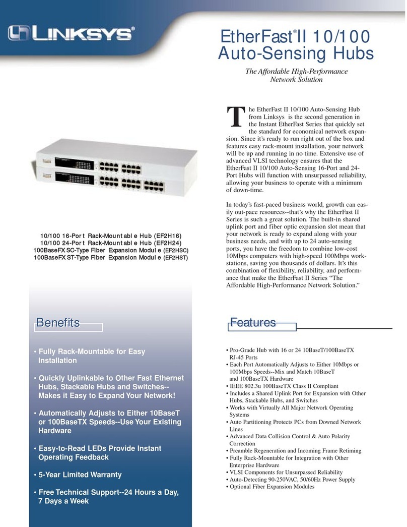
Linksys EF2H16 Specifications
Guralp Systems
Guralp Systems NAM MkII quick start guide

TRENDnet
TRENDnet TEG-40080ES user guide
Dwyer Instruments
Dwyer Instruments PROXIMITY TFLS Series Specifications-installation and operating instructions
LevelOne
LevelOne GTL-2690 installation guide
SMC Networks
SMC Networks 8028L2 installation guide
