Tokyo Keiso M-900 series User manual

TG-F285-2E JAN. 2007K
TG-F285-8E MAY. 2014K
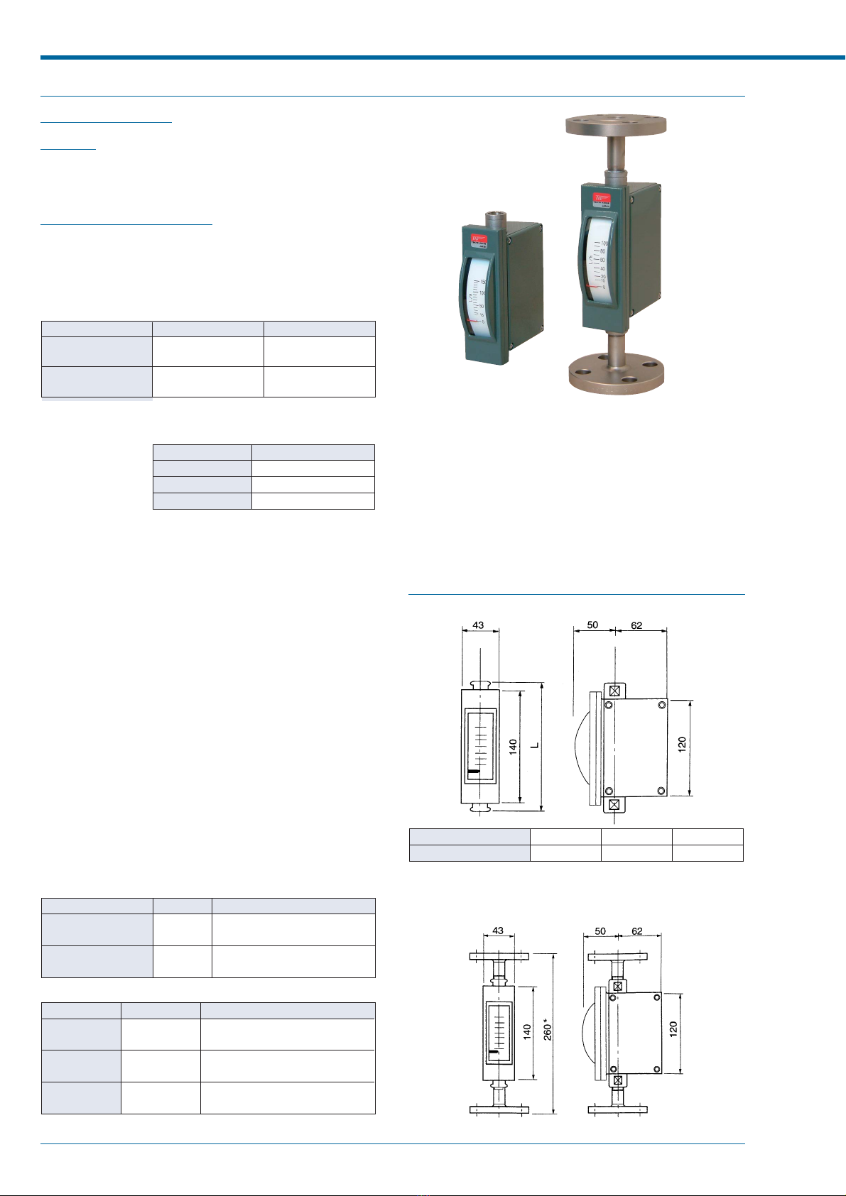
■OUTLINE
M-900 series MICRO FLOWMETER is a metal tube
variable area flowmeter for small flow measurement.
All metallic construction covers even high temperature
and high pressure applications.
Thanks to compact design, M-900 is suitable for
assembling onto various devices. It also covers small
sized industrial processes.
M-900 series MICRO FLOWMETER has been used
for nuclear power plants for long time and HPGSL
certified version is also available.
In addition to local indication, various versions including
pneumatic, electric and alarm output types are ready
to meet your requirements of remote monitoring and
control.
■FEATURES
1. Compact design
Small and light design offers easy installation onto
panels as well as process pipings.
2. High sensitivity
The pivot bearing and light weight pointer enable
to follow float movement swiftly.
3. Suitable for corrosive and opaque fluids
Anti-corrosive materials such as titanium and
MA276 are available to meet your specifications.
4. Easy reading of scale and pointer
The long pointer and wide linearized scale plate
make your reading easier.
5. Supporting devices
Various supporting devices to meet your requirements
are available such as flow control needle valve,
strainer and constant flow valve.
For assembling onto devices, test plants and general
industrial processes
M-900 Series
MICRO FLOWMETER
■OPERATING PRINCIPLE
The flow path has a tapered part. A float in which a
magnet is moulded is located in the tapered tube. The
fluid is introduced from the bottom end of flowmeter
and goes through the tube upward.
Because of the differential pressure produced by the
float and tapered tube, the float is pushed upward and
stops at a position where the weight of float and the
differential pressure balance. Thus, the position of float
corresponds to the flow rate. The moulded magnet in
the float attracts the pointer, and the pointer indicates
the flow rate on the scale plate.
The inside of the tube and indication mechanism are
totally isolated by magnetic coupling.
M-900 Series MICRO FLOWMETER
2TOKYO KEISO CO., LTD. TG-F285-8E
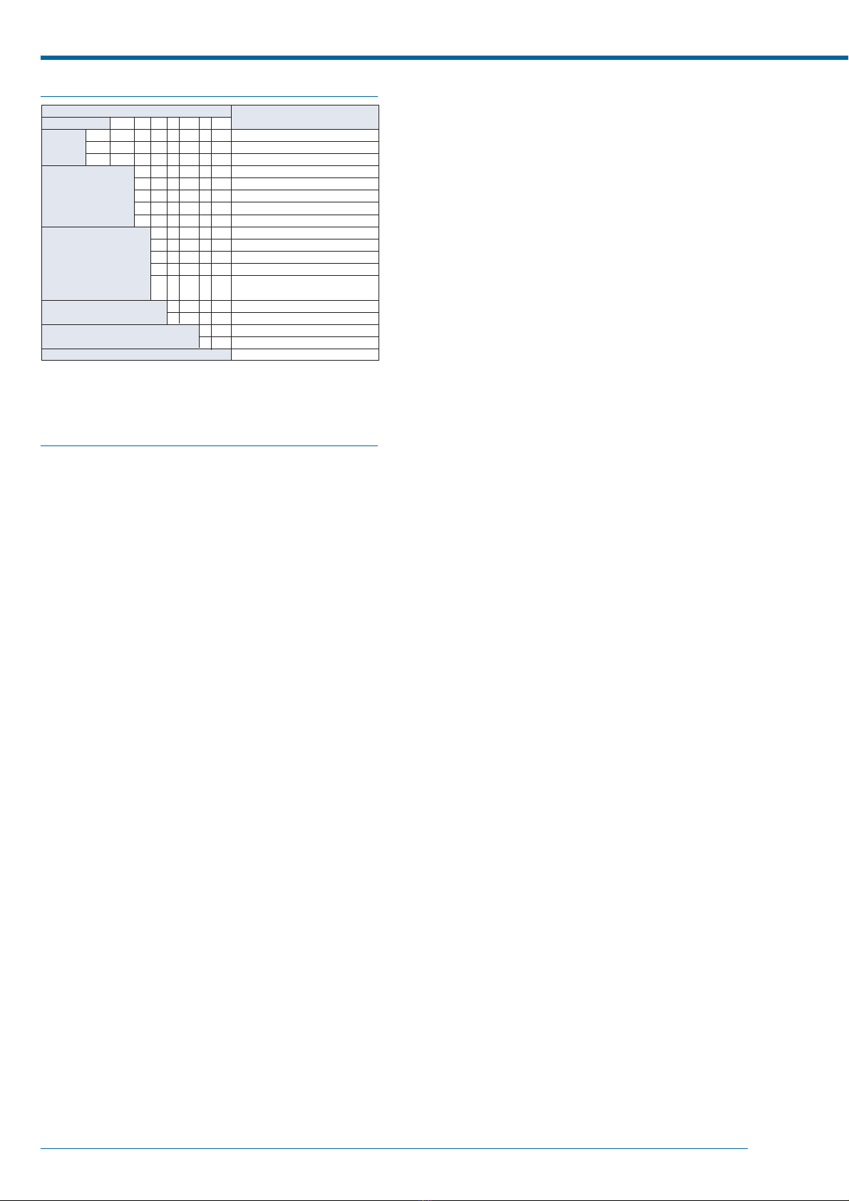
■MODEL CODE
Construction
Function
Flow direction
Additional function 1
Additional function 2
Special
EP–
IS –
M–9
MODEL CODE Contents
0
1
2
5
6
1
2
3
4
5
–
–
–
D
DU
VU
VL
–
–
–
Dust-proof and weatherproof
Flameproof *
1
Intrinsically safe *
2
Local indication
Pneumatic transmission
Electric transmission
Alarm output with reed switch
Alarm output with photo electric switch
Bottom to Top
Bottom to Top side
Bottom side to Top side
Bottom side to Top
Bottom rear to Top rear (only avail-
able for local indicator type)
With liquid damper *
3
With gas damper
Needle valve at outlet
Needle valve at inlet
/Z
*1 Flameproof type is applied only for electric transmission type EP-M-92첸.
*2 Intrinsically safe type is applied only for alarm output type IS-M-95첸.
*3 Liquid damper can be provided on the flowmeters with Bottom side→첸
and Bottom rear→Top rear connections only.
■ADITIONAL FUNCTION
1. Liquid damper Model M-9첸첸-D
A damper mechanism is required for gas and steam
measurement especially at low pressure service to
prevent float hunting.
The damper installed at the bottom of flowmeter
ensures the accuracy and durability of flowmeter.
The damping mechanism works to reduce the
abrupt movement of float utilizing the resistance
generated between oil in the damper and damping
element connected to float rod.
The damper is recommended also for the liquid
service having a pulsation flow.
2. Gas damper Model M-9첸첸-DU
The gas damper which requires no damper liquid
is available for gas measurement. A mechanical
damper consists of a cylinder and a piston
connected with float rod. This type needs no space
for damping mechanism at the bottom of flowmeter.
Therefore, this damper is applied for any direction
type of flowmeters which result in the flexibility of
piping design. Furthermore unnecessary re-filling
of damper liquid improves the maintenability.
The gas damper is effective for the low pressure
gas services which cause hunting of indication and
for the services which does not permit damping
liquids. It is highly recommended to have gas
damper for the services less than 0.3MPa pressure
and without needle valve at the downstream.
However, this type is applicable only for dry gas
services and not applicable for liquids nor
condensable vapors. Neither chlorine gas which is
synthesized easily with other chemicals nor gases
containing foreign materials like rust, dust and oil
is applicable because of the ingress into the piston
and cylinder which might lead to the malfunctioning
of the flowmeter.
3. Needle valve M-9첸첸-V첸
A needle valve used for flow rate control is
recommended at the downstream of flowmeter to
avoid hunting for gas measurement.
On the other hand, for liquid measurement the
pulsation may be eased by the valve located
upstream.
4. Magnet strainer. See clause "Accessories" at the
following page.
The iron particles contained in fluids may cause
the malfunctioning of flowmeter due to the attracted
irons on the moulded magnet in the float. The
particles can be eliminated with the magnet strainer
at the inlet of the flowmeter. For this purpose
dedicated strainer with 100 mesh (optionally 200
mesh) is available.
5. Purge set. See clause "Accessories" at the
following page.
Purge set of M-900 micro flowmeter and constant
flow valve keeps constant flow rate even supply
pressure or down stream pressure is fluctuated.

M-900 Series MICRO FLOWMETER
TOKYO KEISO CO., LTD. 3TG-F285-8E
■ACCESSORIES
NEEDLE VALVES
Needle valve for flow adjustment. It will be assembled onto flowmeter
●STANDARD SPECIFICATION
Nominal size Rc3/8
Fluid pressure Max. 3 MPa
Fluid temperature –15 to +150°C
Material SUS316/PTFE
High pressure versions are available on request.
Consult factory for details
MAGNET STRAINER
A magnet strainer will be assembled into the flowmeter before deliv-
ery on request.
●STANDARD SPECIFICATION
Nominal size 1/4”, 3/8”, 1/2”
Fluid pressure Max. 1.5MPa
Fluid temperature Max. 200°C
Filter Std. 100 mesh
(200 mesh as option)
Material SUS304, SUS316
PURGE SET
Separate TECHNICAL GUIDANCE of "C" Series is available on re-
quest for this version.
●External dimension of M-901-V (With valve)
Thread size
L (mm)
Rc1/4
245
Rc3/8
225
Rc1/2
275
* Screw socket (s) provided for Rc1/4 and Rc 1/2.
* "L" length of the flowmeter with gas damper is
extended by 40mm at downstream.
Standard type
●External dimension of MAGNET STRAINER
●CM-21-900 TYPE PURGE SET
M-900 Series MICRO FLOWMETER
4TOKYO KEISO CO., LTD. TG-F285-8E
■Local Indication version
STANDARD VERSION
OUTLINE
Model M-900 is a local indicator for very small flow measurement.
It indicates flow rate of liquids and gases with a scale and a pointer.
Its purely mechanical construction requires neither electric power nor air.
STANDARD SPECIFICATION
Measuring fluid Liquids and Gases
The model with damper, M-90첸-D or M-90첸-
DU only applied for standard type is recom-
mended for low pressure gas services of less
than 0.3MPa.
Measuring range
Type Water
1 L/h Air
2 L/h(nor)
Standard type Min. 0 to 2
Max.0 to 300
Min. 0 to 300
Max.0 to 600
Min. 0 to 60
Max.0 to 8500
Min. 0 to 8500
Max.0 to 17000
Large flow type
*
*
*1: Water (density 1.0g/cm
3
, viscosity 1.0 mPa·s)
*2: Air at 0°C, 1atm
Viscosity limit for liquid flow measurement
up to 20L/h
20 to 50L/h
More than 50L/h
Full scale Viscosity limit (mPa・s)
5
10
20
Fluid pressure Max. 10MPa
Opt. up to 20MPa
(Subject to flange rating for flange connection
version)
Fluid temperature 0 to 149°C
Consult Tokyo Keiso for the ser-
vice 150°C or more.
Low temperature version
–20°C to –1°C
High temperature version
150°C to 200°C
M-90첸-D and M-90첸-DU
0°C to 149°C
Consult Tokyo Keiso for the service
150°C or more.
Indication accuracy ⫾3% F.S.
However, high accurate type has ⫾2% F.S.
⫾5% F.S. for the measurement less than 10L/h
or 300 L/h (nor) for gas measurement. How-
ever, high accurate type has ⫾3% F.S.
Range ability 10 : 1
10:2 for the measurement less than 5L/h or
150 L/h (nor) for gas measurement. However,
10:1 is available on request.
Process connection
Type
Standard type
Large flow type
Std. On request
Rc 3/8
Rc 1/2
Rc 1/4, 1/2
10, 15, 20, 25mm flange
Rc 3/8, 3/4
15, 20, 25mm flange
Material availabilty
Partname
Body
Taperedtube
Float
SUS304
SUS304
SUS304
Std. Availablematerial
SUS316,(SCS14)SUS316L,
MA276*,Titanium*
SUS316,SUS316L,
MA276*,Titanium*
SUS316,SUS316L,
MA276*,Titanium*
* Not applied for flowmeter with gas damper type.
Paint Munsell 7.5BG4/1.5 (Indicator housing)
AMB. Temp. –30 to 80°C
Enclosure of indication part
Dust-proof and splash-proof (Equivalent to
IP54)
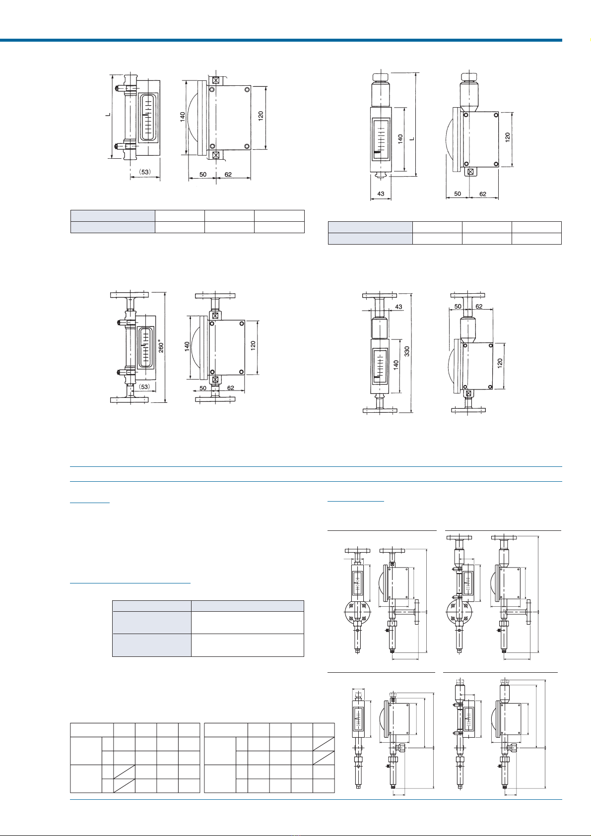
■DIMENSIONS
●STANDARD, SCREW CONNECTION M-901
Screw size
L (mm)
1/4
180
3/8
160
1/2
190
* Screw socket (s) provided for Rc 1/4 and Rc 1/2.
* "L" length of the flowmeter with gas damper is extended by 40mm at downstream.
●STANDARD, FLANGE CONNECTION M-901
* Length of flowmeter with gas damper is extended by 40mm at downstream.
M-900 Series MICRO FLOWMETER
TOKYO KEISO CO., LTD. 5TG-F285-8E
●HIGH/LOW TEMP. VERSION, SCREW CONNECTION M-901 ●LARGE FLOW VERSION, SCREW CONNECTION M-901
Screw size
L (mm)
1/4
180
3/8
160
1/2
190
* Screw socket (s) provided for Rc 1/4 and Rc 1/2.
* The gas damper is not applied for high and low temperature version.
●HIGH/LOW TEMP. VERSION, FLANGE CONNECTION M-901 ●LARGE FLOW VERSION, FLANGE CONNCTION M-901
Screw size
L (mm)
3/8
230
1/2
265
3/4
245
* The gas damper is not applied for this version. AM type is recommended.
FOR GAS SERVICES WITH LIQUID DAMPER
OUTLINE
M-90첸-D equipped with liquid damper is exclusively used for low pres-
sure gas services.
The other specifications are same as the M-900 series used for gen-
eral purposes.
(High and low temperature types are not available.)
STANDARD SPECIFICATION
Measuring range
Type Gases *L/h (nor)
Standard type Min. 0 to 60
Max.0 to 8500
Min. 0 to 8500
Max.0 to 17000
Large flow type
*: Air, 0°C, 1atm
Fluid pressure Max. 3MPa subject to flange rating for flange
connection type.
Flangesize
L
A
L
A
10A 15A 20A 25A
240
100
240
100
240
100
240
100
290
100
290
100
290
100
Screwsize
L
A
L
A
3/8
190
45
260
45
1/2
215
45
270
45
3/4
240
55
1/4
210
40
260
40
Standard
type
Standard
type
Large
flow
type
Large
flow
type
DIMENSIONS
M-904-D
STANDARD, FLANGE CONNECTION LARGE FLOW, FLANGE CONNECTION
* The gas damper is not applied for high and low temperature version. * The gas damper is not applied for this version. AM type is recommended.
L
(150)
120
A
50 62
140
43
120
50 62
(53)
(150)
A
L
140
L(3/8)
(150)
120
A
50 62
140
43
L(1/4,1/2)
50 62
(53)
140
A
L(3/4)
(150)
120
L(1/4,3/8,1/2)
STANDARD, SCREW CONNECTION LARGE FLOW, SCREW CONNECTION

M-900 Series MICRO FLOWMETER
6TOKYO KEISO CO., LTD. TG-F285-8E
■Pneumatic output version
OUTLINE
M-910 is a metel tube micro flowmeter with pneumatic transmitter.
In addition to local flow indication by scale plate and pointer, pneumatic
output of 20 to 100kPa is obtained. Air supply and output pressure
gauges are provided for checking of operating condition. Air-set (Filter
regulator) is optionally integrated.
STANDARD SPECIFICATION
Measuring fluid Liquids and Gases
The model with damper, M-91첸-D or M-91첸-DU
is recommended for low pressure gas services
of less than 0.3MPa.
Measuring range
Type Liquids *1 L/h Gases *2 L/h (nor)
Standard type Min. 0 to 2
Max.0 to 300
Min. 0 to 60
Max.0 to 8500
*1: Water (density 1.0g/cm3, viscosity 1.0 mPa·s)
*2: Air at 0°C, 1atm
Fluid temperature 0 to 80°C
Indication Accuracy ±5% F.S.
Enclosure of indication part
Dust-proof and splash-proof (Equivalent to
IP54)
SPECIFICATION OF PNEUMATIC TRANSMITTER
Output 20 to 100kPa against 0 to 100% span
(0.2 to 1.0 barG available on request)
Air supply 0.14 (±0.01)MPa
Air consumpion Approx. 14L/min. (nor)
AMB. Temp –30 to 60°C
Conduit Rc1/4
Pressure gauge 0 to 0.2MPa range pressure gauges are
provided both for air supply and outlet
Output accuracy ±1% F.S. (against flow calibration)
Enclosure Dust-proof, splash-proof (equivalent to IP54)
The other specifications are same as the M-900 series used for
general purposes.
High and low temperature types, and large flow type are not avail-
able.
DIMENSIONS
●STANDARD, SCREW CONNECTION M-911
Screw size
L (mm)
1/4
180
3/8
160
1/2
190
* Screw socket (s) provided for Rc 1/4 and Rc 1/2.
* "L" length of the flowmeter with gas damper is extended by 40mm at downstream.
●AIR SET INTEGRATED, FLANGE CONNECTION M-911
* Length of flowmeter with gas damper is extended by 40mm at downstream.
M-900 Series MICRO FLOWMETER
TOKYO KEISO CO., LTD. 7TG-F285-8E
■Electric output version
OUTLINE
M-920 is a metal tube micro flowmeter with electric output. In addition
to local flow indication by scale plate and pointer, electric output of
DC4 to 20mA is obtained for remote indication. In addition to dust-
proof and weatherproof constructions, the flameproof version is ready
to cover even the hazardous applications likely at chemical plants.
STANDARD SPECIFICATION
Measuring fluid Liquids and Gases
The model with damper, M-92첸-D or M-92첸-DU
only applied for standard type is recommended
for low pressure gas services of less than
0.3MPa.
Large flow type with damper and flameproof
type with gas damper is not available.
Measuring range
●Dust and splash-proof equivalent to IP54
Type Liquids *1 L/h Gases *2 L/h (nor)
Standard type Min. 0 to 10
Max.0 to 300
Min. 0 to 300
Max.0 to 600
Min. 0 to 280
Max.0 to 8500
Min. 0 to 8500
Max.0 to 17000
Large flow type
Type
Standard type
Large flow type
Liquids *1 L/h Gases *2 L/h (nor)
Min. 0 to 30
Max.0 to 100
Min. 0 to 900
Max.0 to 2800
NOT AVAILABLE NOT AVAILABLE
●Flameproof type with enclosure equivalent to IP65
*1: Water (density 1.0g/cm
3
, viscosity 1.0 mPa·s)
*2: Air at 0°C, 1atm
Fluid temperature 0 to 60°C
Indication Accuracy ⫾5% F.S.
However, high accurate type has ⫾3% F.S.
SPECIFICATION OF ELECTRIC TRANSMITTER
Power supply 24V DC ⫾10%
Output signal 4 to 20mA DC against 0 to 100% span
Accuracy of transmitter ⫾1% F.S. (Against flow calibration)
Max. load 400Ω(at 24 V DC)
AMB. Temp. 0 to 50°C
Insulation resistance 20MΩor more at 500 V DC
Withstand voltage 1000V AC (1min.)
Cable entry G1/2
Construction Dust-proof, splash-proof (IP54 equivalent),
or flameproof *
*d2G4 Approval number 24685
The other specifications are same as the M-900 series used for gen-
eral purposes.
High and low temperature types are not available.
Receiving
instrument
Transmitter
DC24V
+1
2
3
–
+
–
Power
supply
* Ground power supply line at minus polarity.
*
Connection diagram
DIMENSION
●Non-explosion-proof, FLANGE CONNECTION,
M-921(STANDARD)
* 300mm for 1” flange conn.
* Length of flowmeter with gas damper is extended by 40mm at down-
stream.
●FLAMEPROOF, FLANGE CONNECTION, EP-M-921

M-900 Series MICRO FLOWMETER
8TOKYO KEISO CO., LTD. TG-F285-8E
■Alarm output with reed switch
OUTLINE
M-950 is a metal tube micro flowmeter with reed swich alarm contact.
It addition to local flow indication by scale plate and pointer,
alarm contact output at set point is obtained.
STANDARD SPECIFICATION
Measuring fluid Liquids and Gases
The model with damper, M-95첸-D or M-95첸-DU
only applied for standard type is recommended
for low pressure gas services of less than
0.3MPa.
Large flow type with damper is not available.
Measuring range
Type Liquids *1 L/h Gases *2 L/h (nor)
Standard type Min. 0 to 2
Max.0 to 300
Min. 0 to 300
Max.0 to 600
Min. 0 to 60
Max.0 to 8500
Min. 0 to 8500
Max.0 to 17000
Large flow type
*1: Water (density 1.0g/cm
3
, viscosity 1.0 mPa·s)
*2: Air at 0°C, 1atm
Fluid temperature 0 to 80°C
Enclosure of indication part
Dust-proof and weatherproof (Equivalent to
IP54)
SPECIFICATION OF ALARM CONTACT
Type of contact 1 contact by reed switch
Either "a" or "b" instantaneous contact.
Provide holding circuit if required.
Reset span Less than 30% F.S.
Alarm setting Adjustable within the measuring range with ex-
ternal setting knob
Setting accuracy ±3% F.S. (against flow calibration)
Contact capacity 10VA AC (Resistance load), 10W DC
Max. current 0.25 A
Max. voltage 100V DC,125V AC
Insulation resistance 100MΩor more at 500V DC
Withstand voltage 1500 V AC (1 min.)
Cable entry G1/2
Safety barrier Type EB3C-R manufactured by IDEC will be
supplied on your request.
The other specifications are same as the M-900 series used for gen-
eral purposes.
(High and low temperature types are not available.)
Reed switch
Te r m inal
1
2
3
Following diagram shows the
case of non alarming status
Connection diagram
()
DIMENSIONS (M-951 TYPE)
●STANDARD, SCREW CONNECTION M-951
Screw size
L (mm)
1/4
180
3/8
160
1/2
190
* Screw socket (s) provided for Rc 1/4 and Rc 1/2.
* "L" length of the flowmeter with gas damper is extended by 40mm at downstream.
●STANDARD, FLANGE CONNECTION M-951
* Length of flowmeter with gas damper is extended by 40mm at downstream.
M-900 Series MICRO FLOWMETER
TOKYO KEISO CO., LTD. 9TG-F285-8E
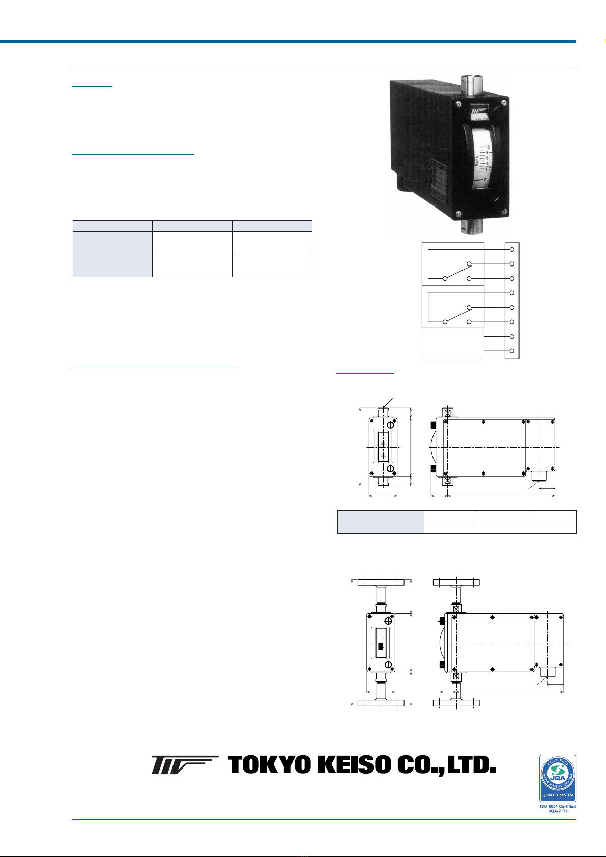
■Alarm output with photo electric switch
OUTLINE
M-96첸is a metal tube micro flowmeter with photo electric switch. In
addition to local flow indication by scale and pointer, 2 alarm contacts
are equipped and their alarm points are set with the external knob.
STANDARD SPECIFICATION
Measuring fluid Liquids and Gases
The model with damper, M-96첸-D or M-96첸-DU
only applied for standard type is recommended
for low pressure gas services of less than
0.3MPa.
Type Liquids *1 L/h Gases *2 L/h (nor)
Standard type Min. 0 to 2
Max.0 to 300
Min. 0 to 300
Max.0 to 600
Min. 0 to 60
Max.0 to 8500
Min. 0 to 8500
Max.0 to 17000
Large flow type
*1: Water (density 1.0g/cm3, viscosity 1.0 mPa·s)
*2: Air at 0°C, 1atm
The other specifications are same as the M-900 series used for gen-
eral purposes.
High and low temperature types are not available.
SPECIFICATION OF ALARM CONTACT
Alarm point 2 points
Contacts 1C⫻2 points relay contact
Setting accuracy ±2% F.S. (against flow calibration)
Reset span Less than 2% F.S. (against flow calibration)
Alarm setting Adjustable within the measuring range with ex-
ternal setting knob
Contact capacity 1200VA AC, 240W DC (Resistance load)
Max. current 10A
Max. voltage 250V AC, 125V DC
Power supply 100V AC⫾10% 50/60Hz
Power consumption 5VA
Insulation resistance 100MΩor more at 500V DC
Withstand voltage 1500V AC (1min.)
Ambient temp. 0 to 60°C
Enclosure Dust-proof and weatherproof
1
2
3
4
5
6
7
8
COM.
N.C
N.O.
COM.
N.C.
N.O.
Connection diagram
Power supply
Amplifier
High alarm
Low alarm
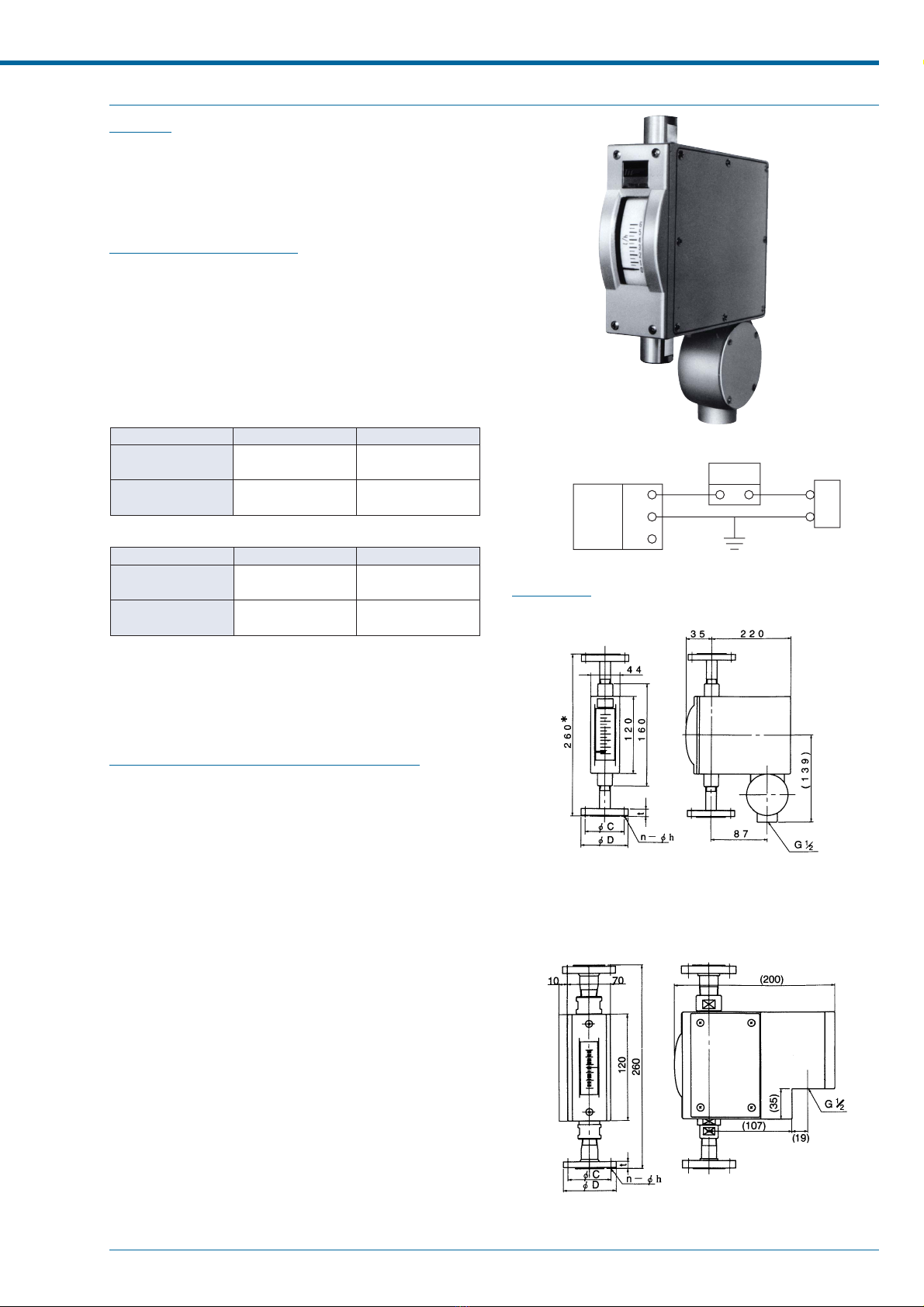
DIMENSIONS
●STANDARD, SCREW CONNECTION M-961
220
32
34
58
160
20120
20
G1/2(F)
2-Rc3/8
Screw size
L (mm)
1/4
180
3/8
160
1/2
190
* Screw socket(s) provided for Rc1/4 and Rc1/2.
* Length of flowmeter with gas damper is extended by 40mm at downstream.
●STANDARD, FLANGE CONNECTION M-961
220
32
34
58
260
7012070
G1/2(F)
*
* Length of flowmeter with gas damper is extended by 40mm at downstream.
Head Office : Shiba Toho Building,
1
–
7
–
24 Shibakoen,
Minato-ku,
Tokyo
105
–
8558
Tel : +81-3
–
3431
–
1625 (KEY) ; Fax : +81-3
–
3433
–
4922
* Specification is subject to change without notice.
Other Tokyo Keiso Measuring Instrument manuals


Popular Measuring Instrument manuals by other brands

Mantracourt
Mantracourt Broadweigh Bluetooth Series Original instructions

Tempo Communications
Tempo Communications TV220E Quick reference card

Stabila
Stabila LD 300 operating instructions

Intec
Intec SA2000 user manual

BRUEL & KJAER
BRUEL & KJAER 4323 Instructions and applications

Ames Instruments
Ames Instruments 57716 Owner's manual & safety instructions


