Tollos Cirrus User manual
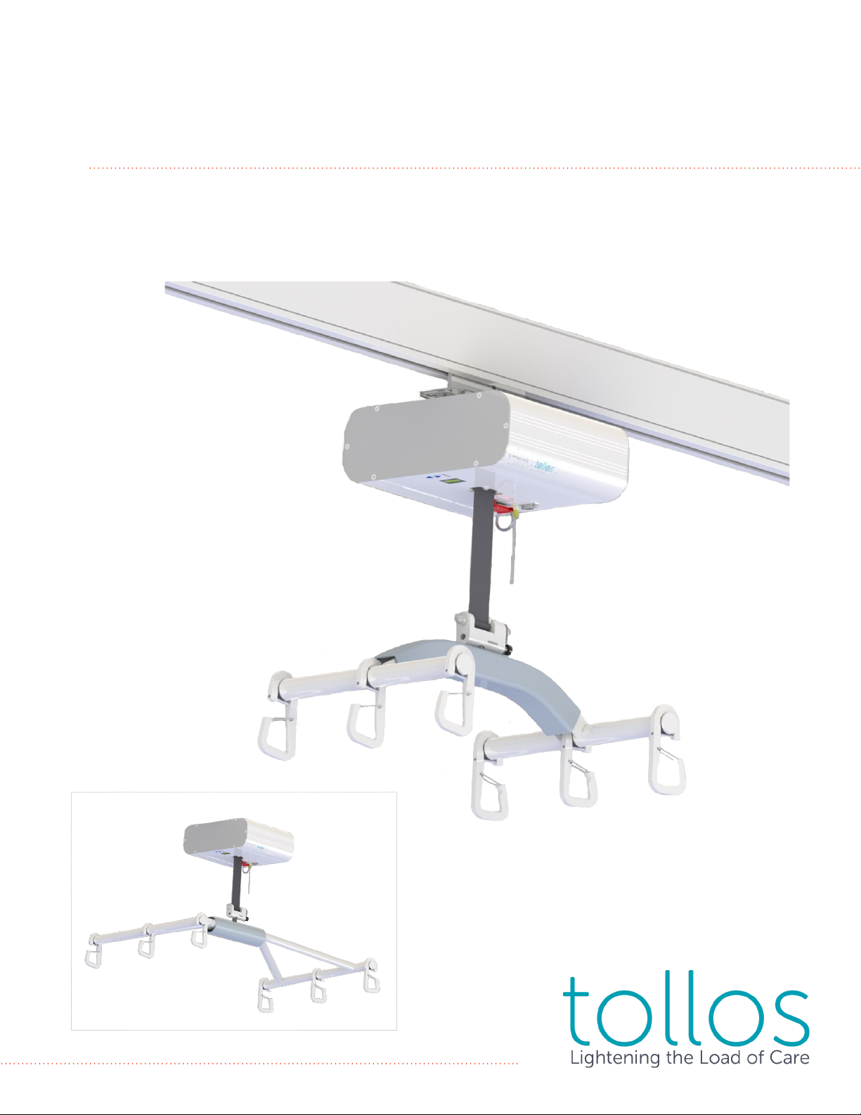
Cirrus®Service Manual
Pinnacle®Service Manual


Table of Contents
Manufacturer
Changing the Batteries
Replacing the Touch Pad
Replacing the Circuit Board
Replacing the On/O Switch
Replacing the Lift Strap
LCD Display Messenging
Exploded View
Maintenance Checklist
Checklist Notes
IC Belt Inspection Notes
Schematics
Troubleshooting Flow
Cleaning & Disinfection
Terms & Conditions
1
2
3
4
5
6
9
10
11
12
13
17
18
19
20

1
Manufacturer
Tollos Inc.
Corporate Oce Canadian Oce & Manufacturing
8 Easter Court, Suite J 75 Dyment Road
Owings Mills, MD 21117 USA Barrie, ON L4N 3H5 CANADA
Western Zone Oce Central Zone Oce
5560 Skylane Blvd., Suite C 930 N Beltline Road, Suite 107
Santa Rosa, CA 95403 USA Irving, TX 75061 USA
Toll Free: 888-363-7224 www.tollos.com
Parts & Service
Please contact Tollos or your local authorized representative for service.
Phone: 888.363.7224 US & Canada
Fax: 410.363.7708
Website: www.tollos.com
Serial Number: _________________________________________
Please have your serial number available when contacting Tollos for service. Please include your serial number in all
communications with Tollos.
WARNING, CAUTION,
IMPORTANT DANGER
AC Adapter Label General Product Label
Read Manual Label Marking on the Hand Controller
Fuse Label Cirrus 750 Label
Duty Cycle Label Pinnacle 1000 Label
Maximum Weight Labels 6-pt Spreader Bar
On/O Label 6-pt Bariatric Spreader Bar
Manual Emergency Down Label Sling Sizing Guide Label
Remove for Access to Manual
Emergency Down Manual Emergency Crank Label
Symbols
2
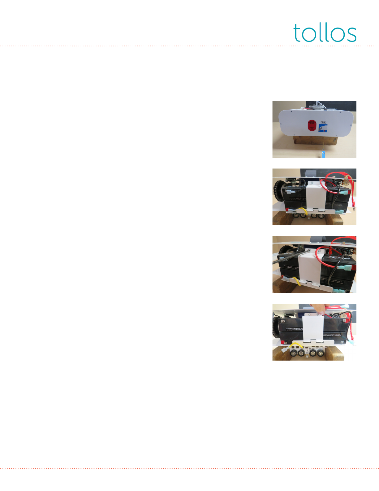
Batteries
Tools needed:
• #1 Robertson screwdriver
• 9/64” Allen wrench
1. Using a #1 Robertson screwdriver, remove the 3 screws from both
the front and back of lift.
2. Remove all cables leading to the batteries.
NOTE: Make a note of where the battery connections are.
3. With a 9/64” hex key, remove all both screws holding the battery
bracket in place. Remove the bracket.
4. Batteries can now be removed. Replace with #5004-113 12V, 2.6ah
batteries. Reverse steps 1-4 to complete installation.

3
Touch Pad
Tools needed:
• #1 Robertson screwdriver
• Wire cutters
• Utility knife
• Isopropyl alcohol
1. Using a #1 Robertson screwdriver, remove the 3 screws from both
the front and back of the lift.
2. Using wire cutters, cut away the tie strap holding the touchpad
ribbon.
3. Disconnect the touchpad from its wiring harness.
4. Use a utility knife to get under the touchpad and carefully peel the
touchpad o the lift.
NOTE: When replacing the touchpad, ensure the surface of the shroud
is clean. Wipe with isopropyl alcohol.
NOTE: Do not bend or fold ribbon cable. Faulty connections will result.
WARNING: Do not use too much force applying the touchpad.
Excess force will result in reduced life expectancy and
malfunction.
4
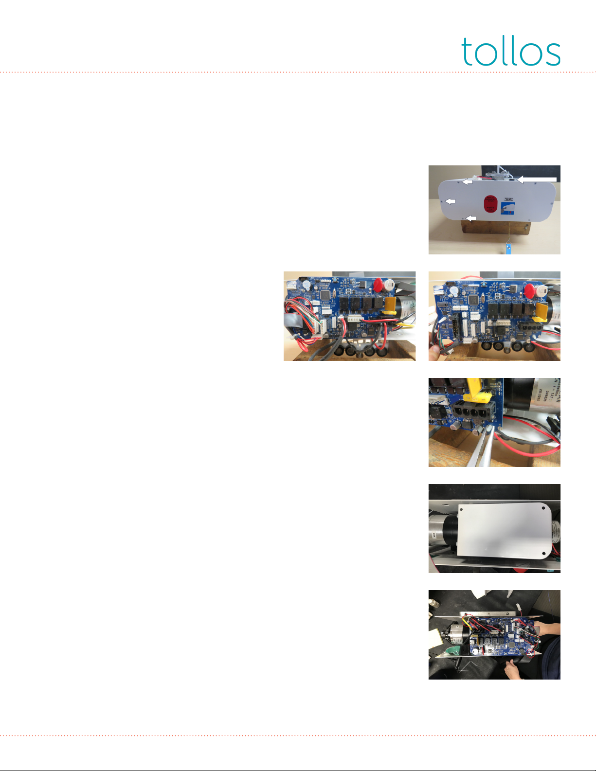
Circuit Board
Tools needed:
• #1 Robertson screwdriver
• Wire cutters
• Needlenose pliers
• Zip ties (x2)
1. Using a #1 Robertson screwdriver, remove the 3 screws from both
the front and back of the lift.
2. Remove all plug connectors from the circuit board.
3. Cut the 2 zip ties that are holding the electrical harness to the board.
4. Using needlenose pliers, pinch the 3 nylon board supports to allow
for removal of the circuit board. Reverse steps 1-4 to complete
installation.
NOTE: Save all nylon mounting board supports for the new board.
(Nylon mounting board supports: part no. 1008-963)
Fuse Holder
1
3
2
Before After

5
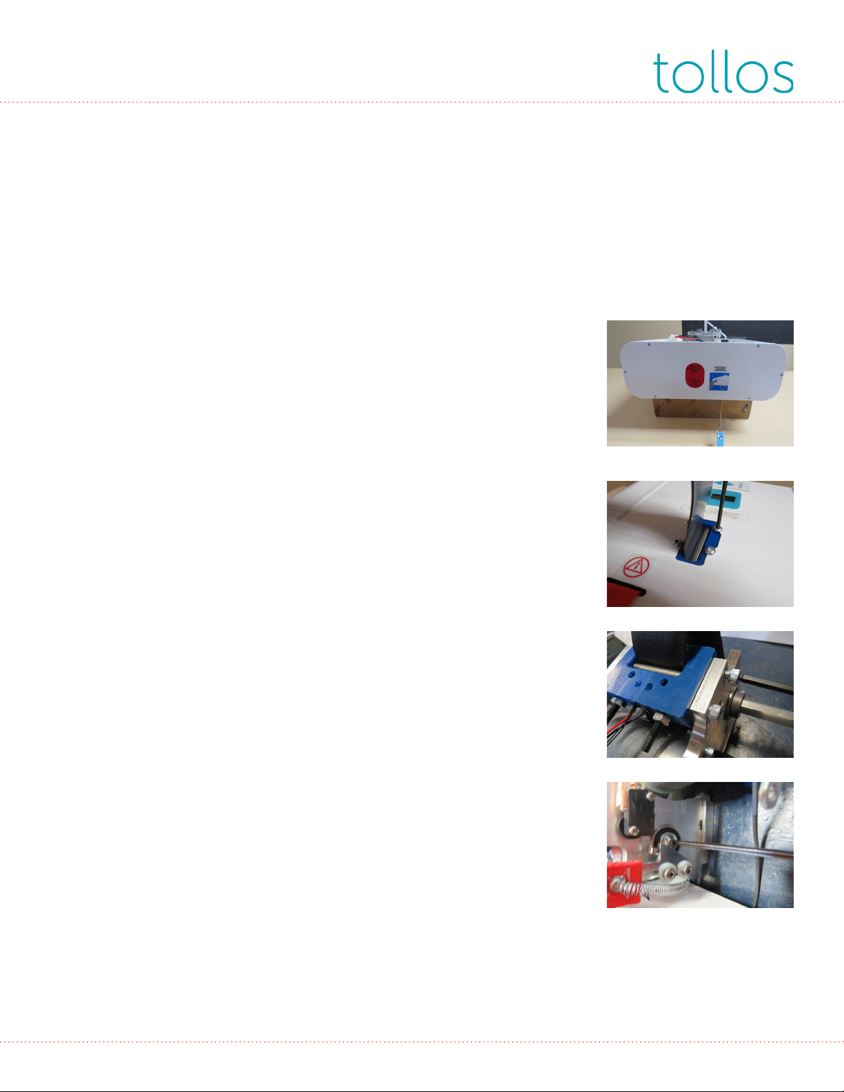
On/O Switch
Tools needed:
• #1 Robertson screwdriver
1. Using a #1 Robertson screwdriver, remove the 6 screws holding the
front plate in place.
2. Remove blue strap.
3. Unplug the on/o switch from the wiring harness.
4. While holding the top of the switch inside the lift, twist the brass
knurled end outside of the lift to remove.
Reverse steps 1-2 to complete installation of new switch.
NOTE: When connecting the new switch to the harness, the cable
connects just complete a circuit. The switch cable and the harness
cable aren’t connected in any particular sequence. It doesn’t matter
which connector on the switch cable is attached an opposite harness
cable.
Emergency Down
On/O Switch
6
Lift Strap
Tools needed:
• Drill, R1 bit
• 1/8” Allen wrench
• 3/16” Allen wrench
• 5/32” Allen wrench
• Pliers or flat-head screwdriver
• Blue LoctiteTM
1. Using the drill with the R1 bit, remove 12 case screws from the end of
the lift.
2. Remove end and side panels.
3. Remove one of the battery leads.
4. With a 1/8” Allen wrench, remove 4 screws securing the bottom
panel of the lift.
5. Remove the bottom panel.
NOTE: Remove all electrical connections from circuit boards & cut zip
ties.
6. With a 3/16” Allen wrench, remove the belt guide block from the
frame. Remove the block pin to fully separate.
7. Using a 5/32” Allen wrench, remove the screw from the end of the
belt spool shaft. Lift the red strap and move level out of the way so the
screws can be removed.
(continued)
7
Lift Strap (cont.)
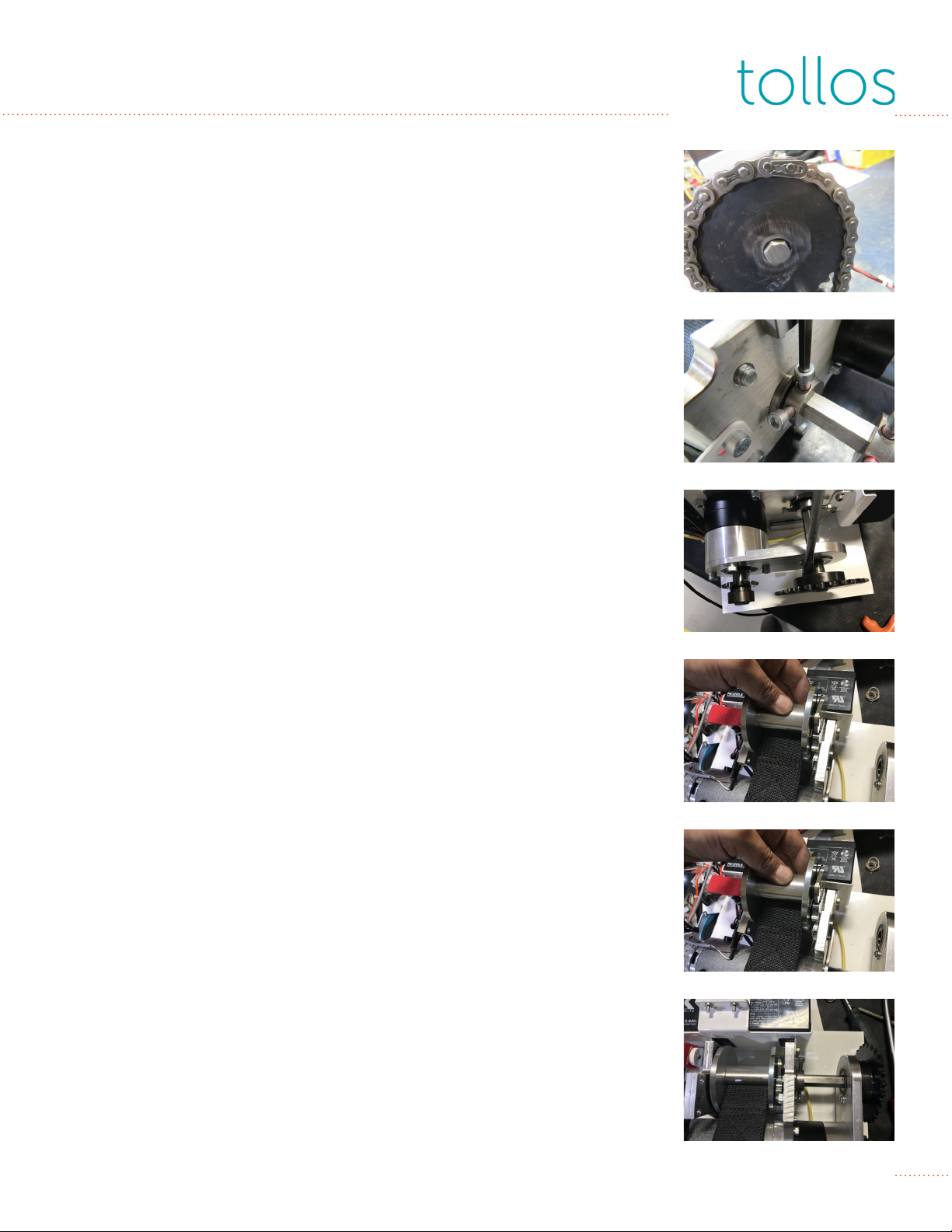
8. Using pliers or a flat-head screwdriver, gently pop o the master link
from the drive chain.
9. With the 5/32” Allen wrench, loosen the set screws on the shaft
collar.
10. With the flat screwdriver, gently tap on the motov spool support to
drive the shaft out of the spool.
11. Remove the belt spool assembly through the top hole (where the
belt guide block was).
12. Remove the damaged strap.
13. Insert the new strap as shown.
NOTE: Make sure the belt is facing up and the belt spool assembly is
properly positioned.
(continued)
8
Lift Strap (cont.)
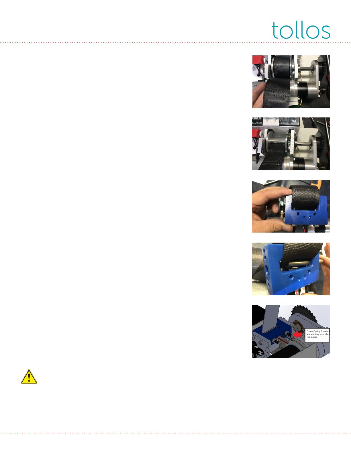
14. Place the shaft back into the spool and reassemble.
NOTE: Use Blue Loctite on the shaft collar screws, the spool shaft
screw, and the hex bushings.
15. Wind up the belt by moving the large sprocket towards the motor.
16. Insert the end of the new belt through the belt guide block.
17. Move the pin through the block. Make sure the plunger pin is on
one side of the shaft pin and the belt is on the other. A screwdriver
may be necessary to move the plungers out of the way of the pin.
18. Ensure belt block is replaced in the correct orientation. Black
plunger screws should be pointed towards the motor as shown. Use
new chain and link provided in the service kit.
Reverse the procedure to complete reassembly of the lift.
NOTE: Thoroughly test the lift to ensure proper and safe function.
CAUTION: Previously used/old chain links and clips should not be
reused due to possible mechanical damage to the holding chain
clip and the cyclical fatigue that the chain link has endured during
its operation.

9
LCD Display Messages
Two sets of messages can be displayed, depending on whether the lift is in normal operation
mode or charging mode.
Normal Operation
During normal operation, the lift will display the current action and the number of times that
action has been performed during the life of the lift.
There are four possible actions:
LIFT UP: #### - Lifetime-accumulated number of Lift Up movements.
LIFT DN: #### - Lifetime-accumulated number of Lift Down movements.
TRAVEL L: #### - Lifetime-accumulated number of Traverse Left movements.
TRAVEL R: #### - Lifetime-accumulated number of Traverse Right movements.
Charging Mode
During the charging period, the display will toggle through several predefined messages. The
message changes every 7.5 seconds.
TTL CYCL: #### - Lifetime-accumulated number of up/down cycles. Please note, this number
will be dierent from the numbers displayed for LIFT UP and LIFT DOWN.
TTL HRS: #### - Lifetime-accumulated number of hours the lift has operated; defined as the
number of hours the motor (lifting or traversing) has been operating.
CHARGES: #### - Lifetime-accumulated number of times the batteries have been charged.
BATT CAP: % - Current level of charge in the batteries; displays as a percentage in increments of
10%.
LOW CHRG: #### - Lifetime-accumulated number of times the batteries have experience a very
deep discharge.
SERVC IN: #### - Displays the number of lift cycles remaining before service is required.
A.S.: % - Displays the lifespan of the lift, takes into account number of lift cycles and patient
weight.
TTL LR: #### - Active when lift is in transverse mode; tracks the number of times the lift has been
moved.
10
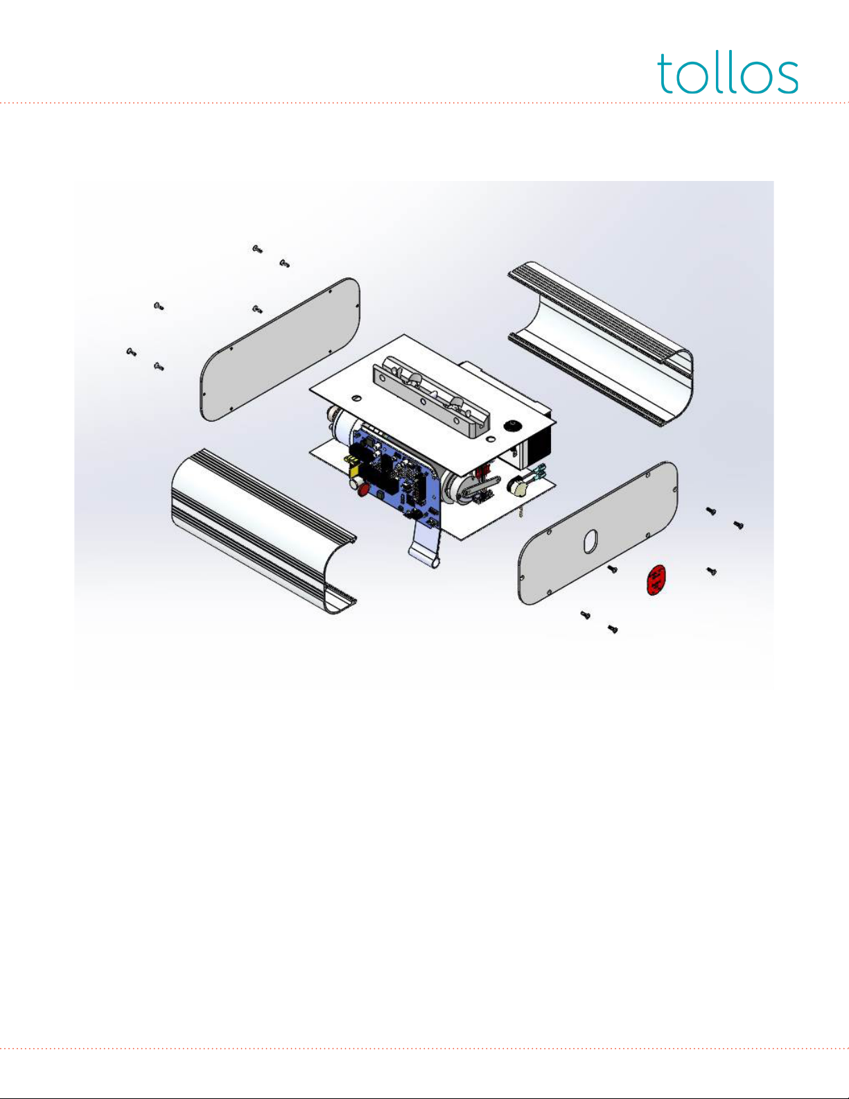
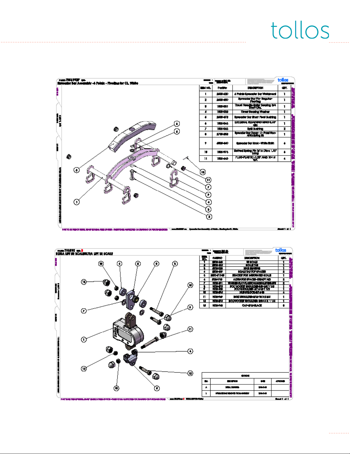
Exploded View
1. Lift Shroud
2. Quick Release Trolley
3. Control Board
4. Drive Chain
1
1
2
3
4

11
Ceiling Lift Inspection Checklist
Date: ______________________________________________________________ Model #: _______________________________________
Facility: ____________________________________________________________ Serial #: _______________________________________
Location: ___________________________________________________________________________________________________________
In Warranty? Yes No D.O.P.__________________________ TTL Cycle: _____________________
Belt OK - N/A Replace/Fix Comments
Cloth belt: stitching, fraying, folding, cuts
IC Belt: weld, folding, cuts, exposed metal strands
(see Notes, pages 13-16)
Trolley (if applicable) OK - N/A Replace/Fix Comments
Inspect wheel motion for free movement
Inspect wheel for visible damage/ flat spots
Inspect trolley drive wheel chain power (traverse only)
Smart Technology OK - N/A Replace/Fix Comments
Scroll through functions
Reset PM alert
Check for low charge
Service in
Operations OK - N/A Replace/Fix Comments
Test upper limit switch
Test lower limit switches
Test manual express down
Test lifting with load
Check noise level
Ensure gear box alignment
Grease brass gear/ worn gear motors only
Electrical OK - N/A Replace/Fix Comments
Test battery output V reading:
Test charge output (26-28 volts) V reading:
Test continuous charge (if applicable)
Test touch pad functions
Test hand control functions
Inspect wiring harness
Inspect circuit board
Inspect all electrical connections
Fasteners OK - N/A Replace/Fix Comments
Re-insert track end stop (if applicable)
Check spread bar side arm nuts (drilled & pinned)
Check all spreader bar retaining clips
Inspect multi-thrust pin (if applicable)
Ensure nuts/bolts are all present and secure
Miscellaneious OK - N/A Replace/Fix Comments
Test scale (if applicable)
Ensure all components are present
Inspect for visual damage
Inspection sticker
Inspected by: ________________________________________________________ Next recommended inspection: _____________________

12
Inspection Checklist Notes
1. Reset PM Alert
Press and hold the three buttons on the hand control (up, down, bottom left). Turn o motor by
pulling on the blue on/o cord. While holding the three buttons, turn on the motor by pulling
the blue on/o cord. There will be two short beeps to confirm reset and the display will read
“SERVICE RESET”.
2. Test Lifting with Load
Batteries much be fully charged. Lifting strap should not be extended to more than 3-4 feet (914
mm - 1219 mm) from the floor and then lifted 19.5” (495 mm) for the Cirrus 750lb (340 kg) lift, or
12” (305 mm)for the Pinnacle 1000lb (454 kg) lift.
3. Test Battery Output
a. Use 12V battery capacity analyzer
b. Batteries should be fully charged before testing
c. Test each battery individually by attaching the leads directly to it
d. They must show a minimum of 12.6V to pass.
4. Test Charger Output
a. Continuous Charge Rail Test:
1. Shut motor o and move lift along track. If motor goes blank, there is a break in
the track.
2. Or use the CC Test Trolley with light. Run the Test Trolley along the track and the
light should stay lit.
b. End Chargers:
1. Shut down the motor, push into charger, charge cycle should begin.
(Charge cycle shown by 1-3 flashing green lights [depends on charge level], then
solid green once charge is complete.
2. Or use the CC Test Trolley with light. Run the Test Trolley along the track and the
light should stay lit.
13
IC Belt Inspection Notes
IC Belt Inspection Details
Specific to lift straps, users should take the following steps to reduce risk:
• Routinely inspect all straps for signs of excessive wear or damage.
} Refer to the pictures on the following pages as examples of wear/damage conditions
requiring replacement.
• Discontinue use of any lifts with straps that show signs of excessive wear or damage.
• Service your facility’s Pinnacle or Cirrus lift(s) by removing and replacing worn or damaged
straps with new straps. Contact Tollos for assistance if needed.
• Educate sta to visually inspect the strap with each use, with instructions to not use lifts with
visibly worn straps and to alert lift maintenance personnel of any concerns.
• As well as having sta inspect the belts before each use, it is recommended that maintenance
or biomed sta (this function varies in dierent facilities) inspect straps on a regular basis as
determined by facility use but at least semi-annually.
All types of lifting straps, including IC straps, are prone to wear and require eventual replacement.
Tollos recommends replacement of any straps showing signs of excessive wear or damage, or at
10,000 cycles, whichever occurs first.
ILLUSTRATIONS
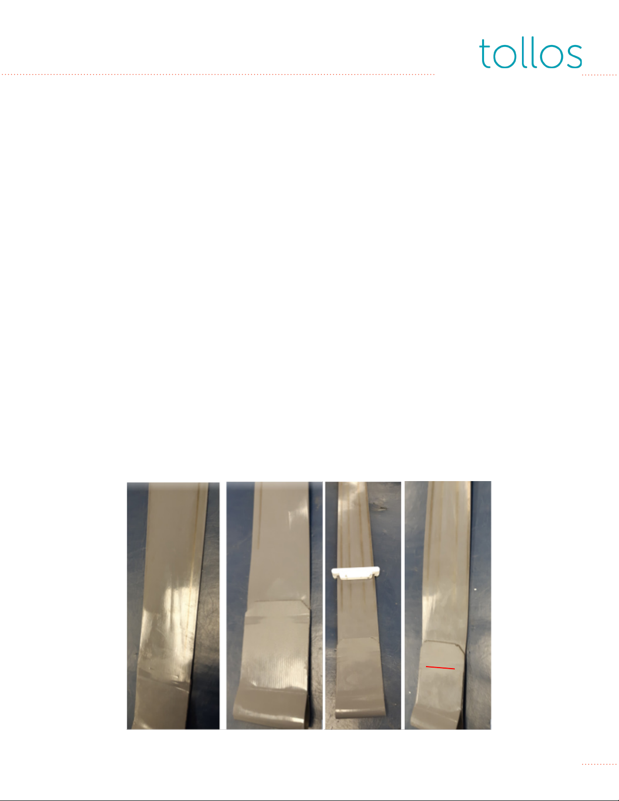
Illustrations 1-4 are examples of IC straps showing signs of normal wear and no structural damage.
These straps are safe to continue to use as long as they have not exceeded 10,000 cycles. If the
inspected straps are at 10,000 or more lift and lower cycles, then replace the straps.
NOTE: The images below were taken during service activities and the clasp is not shown in the
correct position. The correct location of the clasp is just below the fold, shown with the red line
on the picture furthest to the right.)
Illustration 1 Illustration 2 Illustration 3 Illustration 4
14
IC Belt Inspection Notes
Illustration 5 is an example demonstrating wear to the point that the load bearing internal steel
cables are showing. Replace any straps that are worn to this point.
Illustration 5
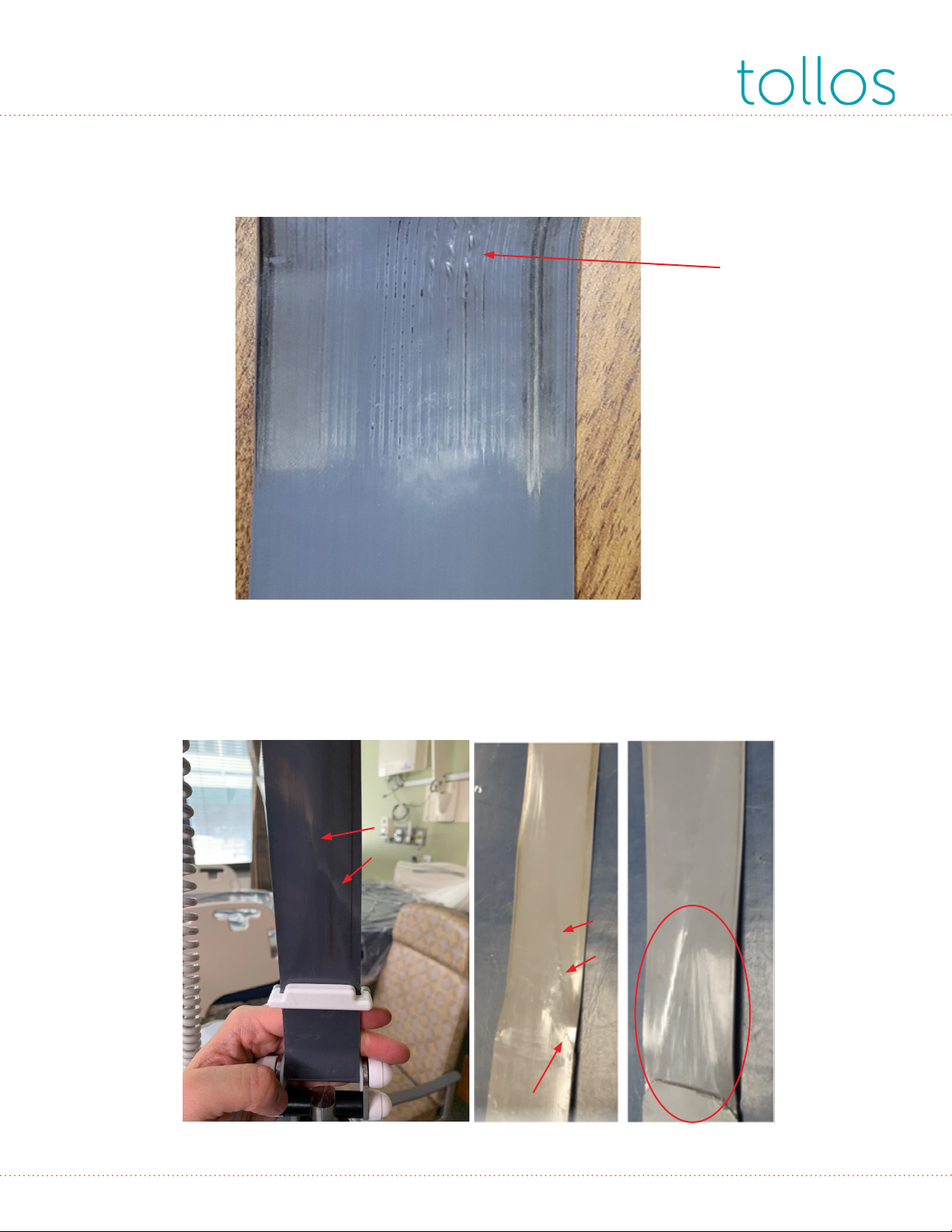
Illustrations 6-8 demonstrate creasing. If creasing is deep, sometimes coupled with cracks, or if
the strap has exceeded 10,000 cycles the strap must be replaced.
Illustration 6 Illustration 7 Illustration 8

15
Illustration 9 demonstrates physical damage. Do not use a lift with a damaged strap, and immedi-
ately replace any straps found to have physical damage.
Illustration 9
IC Belt Inspection Notes
Illustrations 10 and 11 demonstrate a specific type of physical damage – damage to the edge of
the strap. Replace any straps that have this type of damage. (Note that illustration 10 also demon-
strates significant creasing.)
Illustration 10 Illustration 11

16
Illustrations 12-14 demonstrates the exterior appearance of a strap with severe damage to the
load bearing steel cables internally. An x-ray of this strap is included to show the internal damage
that corresponds to the exterior appearance. The close-up image of the opposite side shows the
broken cable ends visible through the polyurethane covering. (Note, this strap also demonstrates
severe creasing.)
Illustration 12 Illustration 13 Illustration 14
IC Belt Inspection Notes
17
Schematics
Other manuals for Cirrus
1
This manual suits for next models
1
Table of contents
Other Tollos Medical Equipment manuals


Popular Medical Equipment manuals by other brands


ResMed
ResMed AirSense 10 AutoSet for Her Plus Clinical Guide

Otto Bock
Otto Bock Dorso Carezza Posture 50R49 Instructions for use

DryShield
DryShield DS1 user guide

Ossur
Ossur LIVINGSKIN Instructions for use

NanoVibronix
NanoVibronix UROSHIELD user manual

Fresenius Medical Care
Fresenius Medical Care 2008 Series Rebuild Instructions