TOM.bv AMIGO Norm NM User manual

ASSEMBLY INSTRUCTIONS
This assembly manual concerns indications for a correct execution and for the maintenance of this new cycle
(read this manual before you assemble and use this article). Adult assembly is required. Keep this manual for
future reference. If you have problems or questions please contact our customer service at customerservice@
tom-bv.com. When you remove/pull the black protection pads on the front and rear axles, look rst if you do
not take away a screw inside this pad before throwing away.
- Have a good time with this bicycle!
Adult supervision is required. Draw attention to your child concerning possible danger. The cycle contents to the
established European norm DIN EN 14764 (minimum Saddle height 635 mm) or DIN EN 14765 (minimum saddle
height 435 mm to maximum height 635 mm) + DIN EN 14782 A responsibility of the manufacturer is out of the
question by imprudent use of the cycle by your child.
It is required by use of this cycle to wear practical clothes and closed shoes. AMIGO Bicycles advise to wear a helmet.
The helmets be found in our assortment (www.internet-bikes.com). This cycle can not be used for sporting use (by
example jumping etc.).
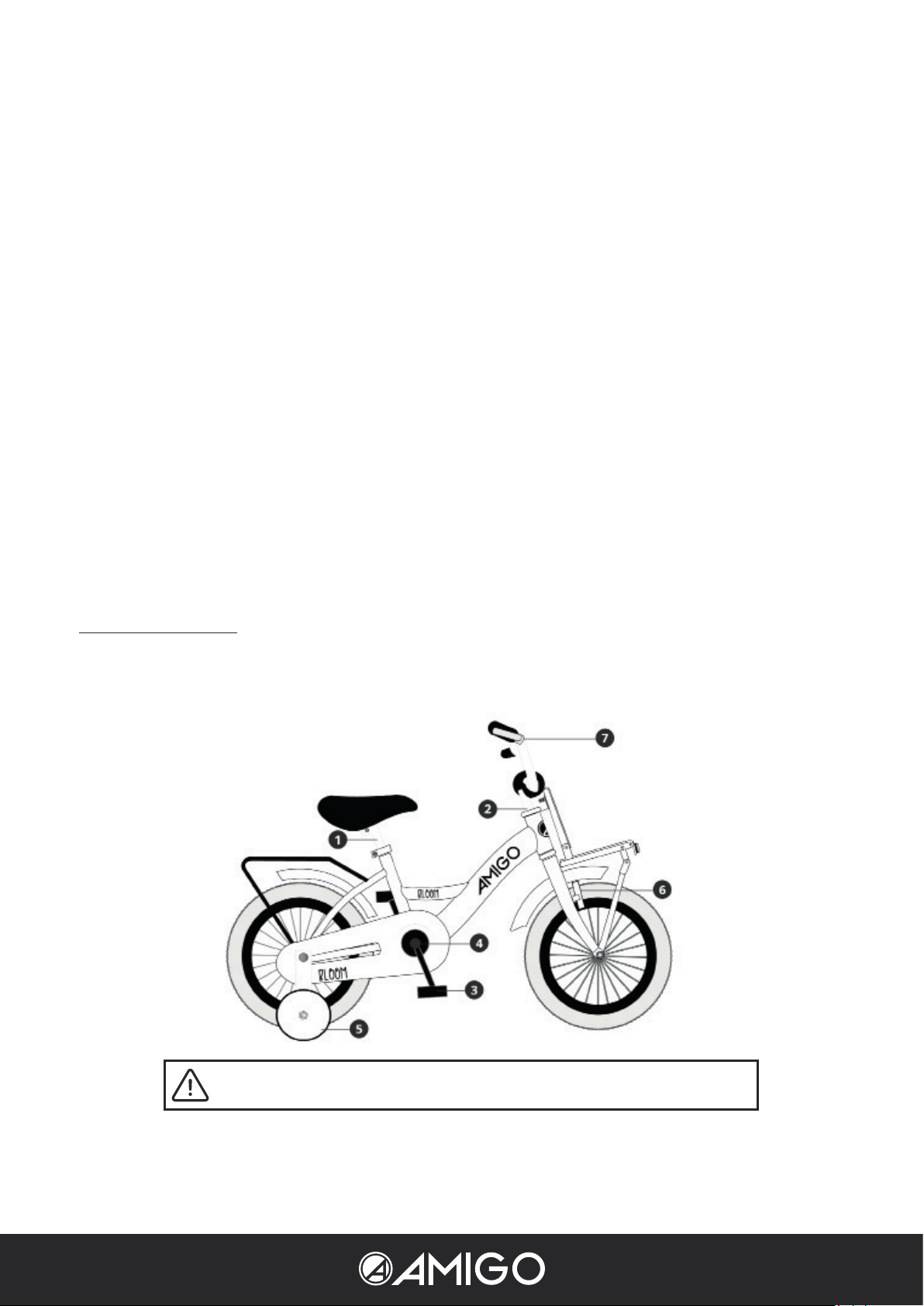
Take the cycle out of the packing and collect all of the parts. Check if all the parts are available.
ASSEMBLY ONLY ALLOWED BY AN ADULT.
Made by TOM.bv
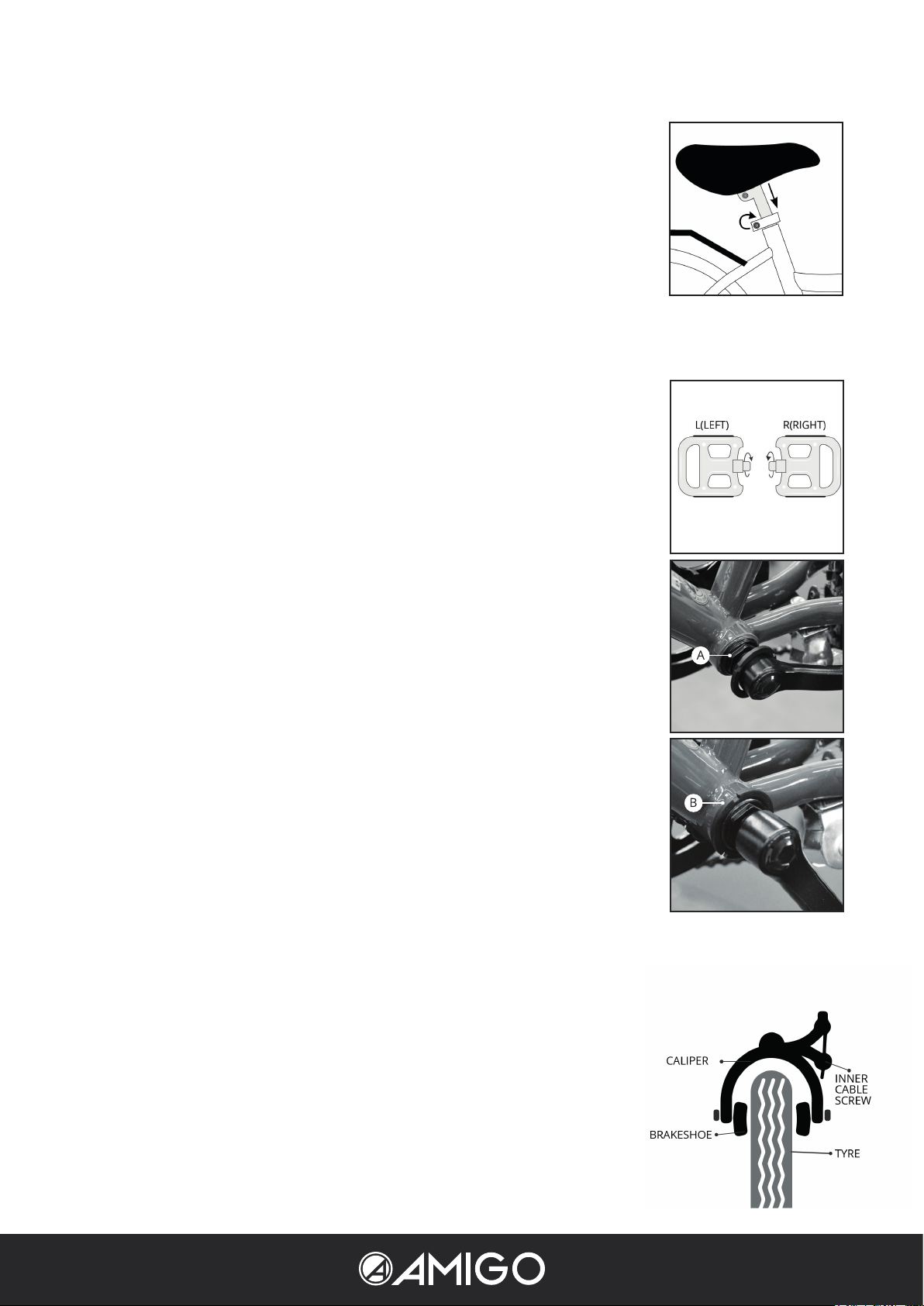
1. Assembly of the saddle
Place the saddle with the pen in the saddle tube. Watch the safety marks on the pen.
Put the saddle on the correct height for your child. You can adjust the saddle that at
least the toe will reach the ground, for preference the whole foot touches the ground to
guarantee a better stand. Attach the saddle and turn on the saddlebold.
2. Assembly handlebar and handlebar pen
Insert the handlebar and the front fork in the head tube. Watch the safety marks on the
pen. Adjust the handlebar at the correct height and tighten the handlebar clamp.
3. Assembly of the pedals:
Look for the R or L marked on the pedal spindle. Or with dashes on the left pedal. This
means that the pedal marked with R will be rotated in the right crank (chain side) and
the pedal marked with L or dashes will be rotated in the left crank. Very important:
check the pedal attachment at least every 3 months. These can come o slowly
when used, resulting in broken threads and/or pedal release.
4. Check the bottom bracket nut
On some bicycles, the left crank is stuck with a bottom bracket nut. Always check that it
is correctly tightened before use.
1. First tighten the nut with the 6 sides [A]. Turn it clockwise to the right.
2. Then tighten the lock nut with 3 notches [B].
5. Assembly trainer wheels
Do not remove the thin axle nut. Install the training locking bracket, with prong towards
the rear of cycle. Be sure prong on locking bracket ts into the axle slot on frame. Install
outside axle nut, and tighten. As you are tightening the axle nut, adjust the trainer’s
height by moving the trainer up or down, until you have the desired height. The trainer
should be approximately 6 mm of the ground. If extra training wheel plate available put
the 2 screws in this plate. Be sure all nuts are adjusted properly and tightened securely.
Check trainer wheels for safety before your child rides this cycle. Do not ride cycle
without trainer wheels attached (12,5 – 16 inch).
6. Brakes
1x handbrake frontwheel en back-pedalling brake on the rear wheel. By back
pedalling the brake working will be operative.
7. Assembly/adjustment of the handbrakes
The handbrake is pre-assembled. Check if the brake-blocks are touching the rim
when you brake. If necessary (re)adjust. Check if the brake is working according
the instructions. If the margin in the handbrake is too large, than rotate the brake
cable nut by the handle. Squeeze the brake and check if both of the brake blocks
are touching the rim. If they do not, than, unscrew the inner cable nut, put the brake
blocks with your hand against the rim, draw with the other hand the inner cable
tighter and rotate the inner cable nut again.
If additional brake adjusting is required you can bring the brake rubbers closer to the wheel rim by turning the
adjusting screw counter-clockwise. Be sure the cable is locked securely through the anchor bolt. Reset the cable
adjuster lock nut when adjustment is nal.
WARNING:
If you have problems with the adjustment, please do not use the cycle and have the
brake repaired or adjusted at a bicycle service shop.
8. Cantilever brakes or V-brakes
The brake shoe/brake block by the V-brake/Cantilever brakes have to run parallel with the
rim. The distance between the brake blocks and the rim must be 2-3 mm. You can adjust this
distance by unscrewing the locknut. When the brake shoe/brake block can not be adjusted
with this locknut and the shoe/block is not yet wore out, than it is possible to adjust the brake
block straight to the brake or rim. Than rst turn back the locknut at the brake grip for having
the possibility to adjust this later again. Than release the nut at the reverse side of the shoe/
block and slide the block closer to the rim. Screw down the nut very tight. Pay attention that
the left and the right brake shoe/brake block are adjusted at the same distance of the rim.
Important is, that the brake shoe/brake block is adjusted that high that during the brake, the
brake shoe/brake block not become under the rim. For further information, see our pictures.
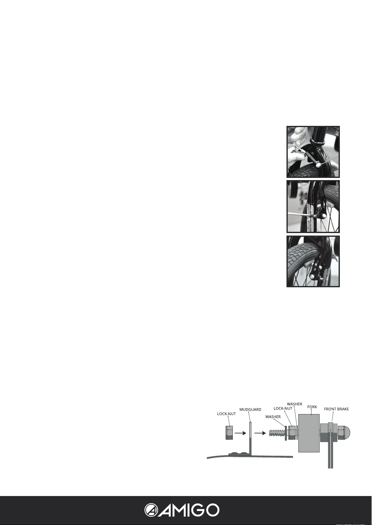
9. Front fender assembly
Bike equipped with canti brake or V brake
1. Remove the nut washer and bolt, holding the front fender to the fork steer tube.
2. Place the front reector (if any) on the front side of the bolt, between the ring and the bolt
end. Same as with front lights (if tted).
3. Hold the front reector or front light (if tted) with 1 hand and in the correct position.
4. When at on the mudguard, push the suspension hook of the mudguard upwards (do not
break). Place it at the back of the hole in the front frame/fork on the bolt.
5. Then insert the ring and then nally tighten the nut.
6. Look when the front reector is ,in a straight position. Then you can tighten the nut very well.
7. Check this screw after a while. May come o again due to vibrations.
Bike equipped with caliper
1. Turn the washer nut of the disc bolt on the back of the front brake. Do not remove the nut from the front! Push
the screw bolt through the hole in the front frame/fork. Keep 1 ring on the front.
2. Caliper front brake must always be on the front of the frame/fork. Not at the back!
3. Place the front reector (if any) on the front side of the bolt, between the ring and the bolt end. Same as with
front lights (if tted).
4. Hold the front reector or front light (if tted) with 1 hand
and in the correct position.
5. When at on the mudguard, push the suspension hook of
the mudguard upwards (do not break). Place it at the back
of the hole in the front frame/fork on the bolt.
6. Then insert the ring and then nally tighten the nut.
7. Look when the front reector/illumination is in a straight
position. Then you can tighten the nut very well.

10. Adjusting the back-pedal brake for children’s bicycles
For children’s bikes, it is advisable to check that the rear wheel does not turn stiy
before use. If this is the case, the cause is often due to the back-pedal brake that is set
too tightly.
1. The back-pedal brake is located at the rear wheel axle. It is attached to the frame
on the left side with a connection [A].
2. Loosen the [B] screw of the connection.
3. Turn the connection back one turn, counter-clockwise.
4. Re-attach the connection.
11. Lubricant
Bearings of naves, head tube and pedal axle are already greased in the factory and we advise you to grease these
regular. To grease these bearings, the parts have to be dismantled. This better can be done by a bicycle service shop.
This also applies to the chain or the navelining and brake cable directions.
12. Camshaft wheels
Note: The wheels must be checked before you start using the bike. By adjusting the spokes, you prevent pulsing in the
wheel. Use a spoke wrench to do this.
1. Check that all spokes are evenly tensioned by lightly squeezing two spokes.
2. If one or more spokes are not evenly tensioned, they should be tightened.
3. Tighten the loose spokes by half a turn and check again.
4. Wait a month and then check all the spokes again.
Warranty
It contains the legal warranty. Damages, which are created by wrong requirements, force, insucient maintenance or
by normal wastage, are locked out of warranty.
1. 10-year warranty on the frame and fork.
2. Five year warranty on the paintwork on rusting from the inside.
3. One-year warranty on all parts except the tires.
Recommendations
1. Check your cycle regular on any damages, wastage or released parts. You have to hold the sides of the rims fat
free.
2. The chain must be oiled regular (chain or universal oil).
3. Check the pressure of the tires regular.
4. The pedals must be attached very well.
5. Pay attention that your child is wearing closed shoes when it is cycling.
6. Pay attention, that your child is wearing always a helmet when it is cycling.
7. If you can not repair the cycle by yourself, please go to a cycle service shop.
8. Parts which are attached by you out of the way or changements which are placed to the cycle (in particular to the
brake installations) are changing the driving-properties and this can be dangerous.
9. Use only original parts when you are repairing the cycle.
Summary of screw parts of the cycle:
Part Norm NM Norm lbf.in
Axle nut in front 22 - 25 195 - 220
Axle nut at the back 25 - 29 220 - 225
Foreforkbolts 15 - 17 130 - 150
Handlebar screw 16 - 18 140 - 160
Saddle screw 16 - 18 140 - 160
Saddle supporting screw 9 - 12 80 - 105
We have worked with full devotion to deliver a product of high quality. AMIGO Bicycles has a complete assortment
for children from 2 years old in modern colours and trendy styles. You can visit also our website:
www.internet-bikes.com.
Belangrijk: indien de ets is voorzien van wielmoeren, zorg er dan voor dat deze niet worden verwijderd
met de wielas beschermers. Trek deze beschermers eraf in plaats van ze af te schroeven.
Max 60 Kgs for 12”/14”/16” under ISO-8098
Max 60 Kgs for 16”/18” under ISO-4210
Max 115 Kgs for 20”/22”/24”/26” under ISO-4210
This manual suits for next models
1
Table of contents


