Tomei 255 lph User manual
品番
(PART NUMBER)
適合
(APPLICATION)
日本語 **************2p
English **************7p
●この取扱説明書を良く読んでからお使いください
●日産自動車の発行する整備要領書と併せてお使いください
●取り付け後も大切に保管してください
●販売店様で取り付けをされる場合は本書を必ずお客様へお渡しください
TOMEI 製品のお買い上げありがとうございます。
タービンやカムを交換してエンジンを高出力化すると、その吸入空気量に見合った燃料の確保が必要です。
TOMEI大容量ポンプはトロコイド式を採用し、ノーマルとほぼ同じ外観でありながら大容量化を実現しました。
タービンやカムを交換するときにECUやインジェクターとあわせて、適正な組み合わせでお使いください。
また、ポンプをブラケットに結びつける危険な取り付け方法ではなく、完全ボルトオンでキット化しました。
●Read this manual carefully prior to the installation.
●Refer to the Nissan official Service Manual along with this Manual.
●Keep this manual for future reference after the installation has been completed.
●Give this manual to the owner when the installation was performed by another person or a shop.
Congratulations on your purchase of the quality TOMEI product.
It is critically important to ensure an adequate supply of fuel corresponding to the intake air volume when
upgrading the turbo and/or camshafts to increase the engine's performance.
The TOMEI high-flow fuel pump adopts the trust-worthy trochoid design which allows for increased capacity
while maintaining a similar appearance and size to the stock pump.
Please tune and use this product in the appropriate combination with the ECU, injectors, turbo and/or camshafts.
This product is designed to drop-in the stock fuel sender unit unlike most of aftermarket pumps on the market
that are designed to be just tied onto the bracket which is not a safe way to upgrade the fuel pump.
255 lph
350 lph
183021
183022
BNR32
M18K19 2023年12月
大容量フューエルポンプ BNR32
INSTALLATION MANUAL
OVER SIZE FUEL PUMP for BNR32
1
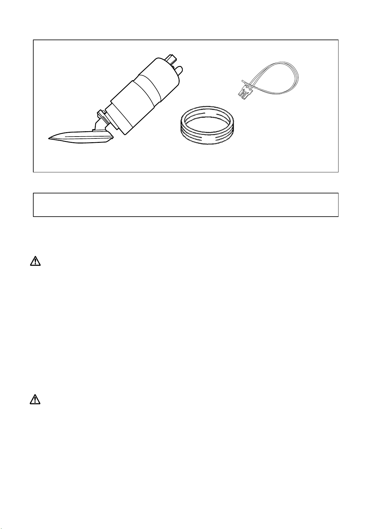
下記の内容/数量が揃っているかを確認してください。 ( )内は同梱の数量です。
■本品は自動車競技専用部品です。サーキットや公道から閉鎖されたコース内に限って使用してください。
■一般公道で使用すると車両本来の安全性が損なわれ危険です。また、法律で罰せられます。
■本品の取り付けは特別の訓練を受けた整備士が、設備の整った作業場で実施してください。
■指定する車種以外への取り付けはおやめください。本品およびエンジンを破損する恐れがあります。
■各ボルトの締め付けはトルクレンチを用いて、規定トルクで締め付けてください。規定トルクで締め付けないとボルトが緩んだり、
ボルトを破損する恐れがあり危険です。
■締め付け部は定期的に点検してください。
■部品脱着の際には無理な力を加えないでください。部品を破損する恐れがあります。
■取り付けの際は、適切な工具、保護具を使用しないと、けがにつながり危険です。
■必ず日産自動車の発行する整備要領書の指示に従い脱着を行ってください。
■ガソリンの漏れ、にじみは運転前に必ず点検してください。ガソリンが漏れると火災の恐れがあり危険です。
■本品はエンジンの仕様に応じたインジェクター、ECU等とあわせて使用してください。
■本品の取り付けはエンジン及びエンジンルーム内が冷えた状態で行ってください。
■部品欠落による車輌の破損・火災が起こる可能性があるため、製品構成部品の取り付けは確実に行ってください。
構成部品
取り付けに必要な工具類
・エンジン整備用工具一式 ・整備要領書
警告
注意
ポンプ本体 (1)
シールパッキン (1)
ハーネス (1)
2

本品の取り付けに際しては燃料系統の脱着を伴い、ガソリンが流出します。作業に際しては下記事項を確実に守ってください。
守らないと爆発や火災の恐れがあり危険です。
■
作業場所を指定し、作業場所以外では作業しない。
① 風通しの良い場所。
② 周囲に火気(溶接機・グラインダー・電動モーター・ストーブなど)の無い場所。
③ 気化した燃料が充満する恐れがあるピットなどから離れた場所。
■
火気使用・火花発生作業は行わない。
① 電気機器の使用禁止。
・ 原則として作業等には使用しないこと。
・ 燃料抜き取りには電動ポンプおよび、ポリタンクを使用しないこと。
・ 溶接機・グラインダー・ドリルなどを使用しないこと。
② 火花発生作業の禁止。
・ 火花発生の恐れがある作業(ハンマーの使用など)はしないこと。
■
静電気の防止および、安全への配慮を行う。
① 消火器を準備する。
② 静電気を防止する。
・ 足元が滑らない程度に床に水をまく。
・ フューエルチェンジャー・車両・フューエルタンク間にアース線を接続する。
③ 燃料が付着したウェスを分別処理する。
■
タンク内のガソリン残量が空に近い状態で作業すること。
■
ホースを抜くと配管の中に残ったガソリンが流れ出ます。ウェスなどを使って広がらないようにする。
■
取り出し作業中にごみなどがタンク内部に侵入しないようにする。
ガソリンに関わる警告
3

作業を始める前に、ガソリンタンク内のガソリン量を空に近い状態にしてください。
(1)燃料配管内のガソリンを除去する。
① フューエルポンプヒューズを取り外す。
② 燃料フィラーキャップを外し、タンクの内圧を抜く。
③ エンジンを始動し自然に停止した後、3~4回クランキングしてガソリンを消費する。
④ イグニッションスイッチをOFFにし、バッテリーのマイナス端子を取り外す。
(2)燃料タンクより、フューエルゲージASSYを取り外す。
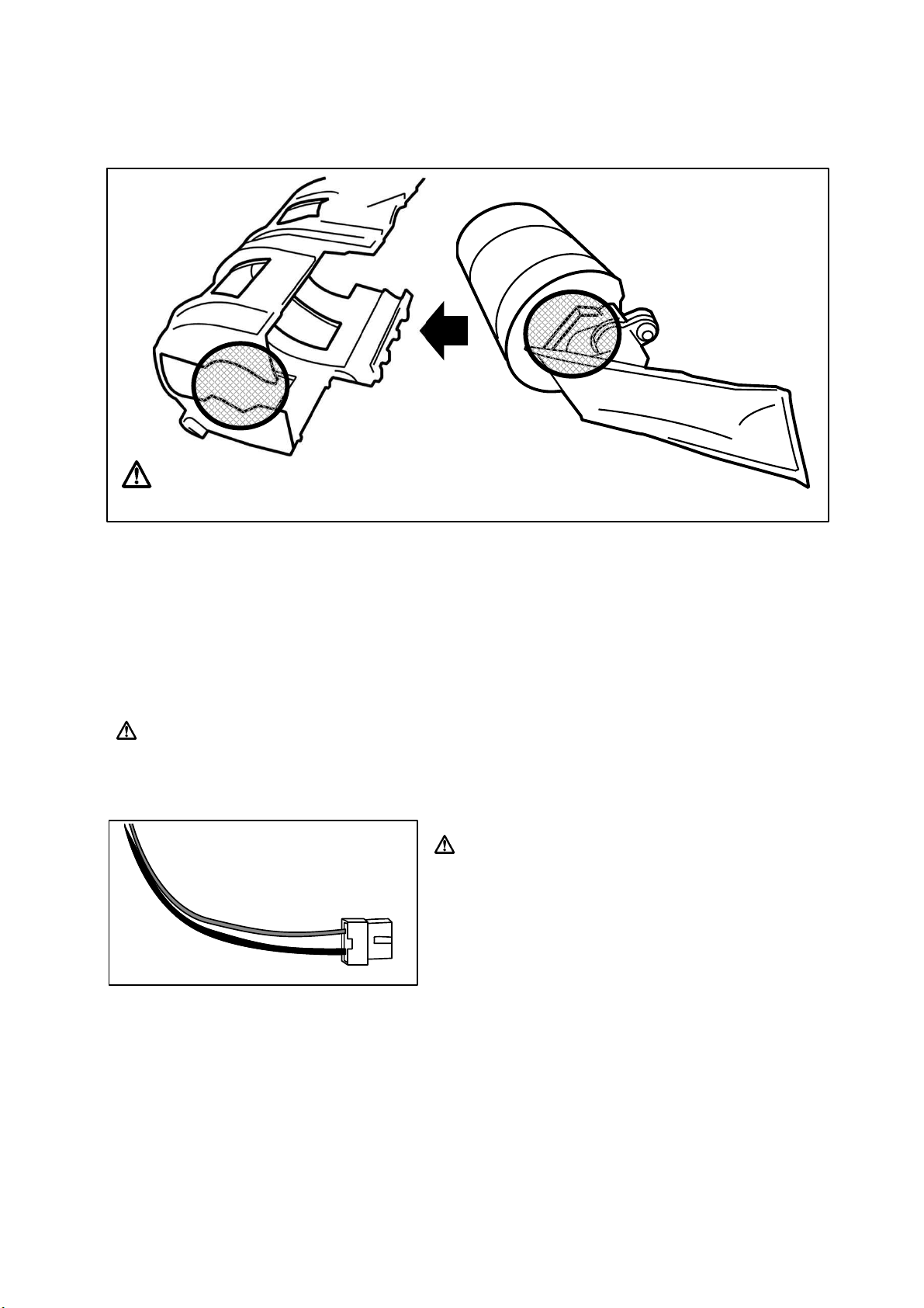
(1)フューエルゲージASSYからフューエルポンプASSYを
取り外す。
シールパッキンは再利用しません。
復帰時では付属品を使用して装着します。
(2)フューエルポンプASSYからフューエルポンプを外し
ポンプカバーおよびポンプブラケットを取り外す。
純正ポンプ以外の部品は再利用します。
1. 準備
2. 取り外し
シールパッキンは
復帰時では付属品を
使用します。
フューエルポンプASSY
ポンプカバー
チャンバー
ポンプ
ポンプブラケット
4

(1)ポンプカバーにフューエルポンプ本体を取り付ける。
ポンプカバー底部の穴形状とポンプ本体のイソレーター凸部形状を合わせ、取り付けてください。
(2)ポンプカバーにポンプブラケットを取り付ける。
(3)チャンバーを取り付ける。
この時、ポンプブラケット裏側のガイドをチャンバーの溝に合わせ、ブラケットの爪がチャンバー受け側と確実にロック
するように固定する。
(4)チャンバーの底に燃料ポンプフィルターが収まっていることを確認する。
ズレがある場合はポンプ本体の位置を調整してください。
(5)車両側のポンプハーネスからカプラーを切断し、付属のハーネスに切断したポンプハーネスを接続する。
+- の極性に注意してください。
(6)フューエルポンプおよびその他の部品を、取り外し時と逆の手順で組み付け、車両に復帰する。
3. 製品の取り付け
5
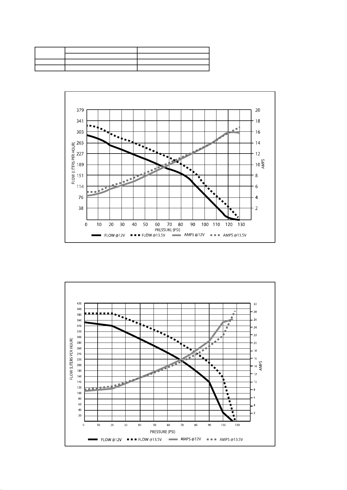
183022
吐出量(276KPa/40PSI 時)
350 l/h
12.0V
13.5V
183021
255 l/h
215 l/h
吐出量(276KPa/40PSI 時)
300 l/h
仕 様
255L/h Fuel Pump Liters Per Hour Flowchart
350L/h Fuel Pump Liters Per Hour Flowchart
6
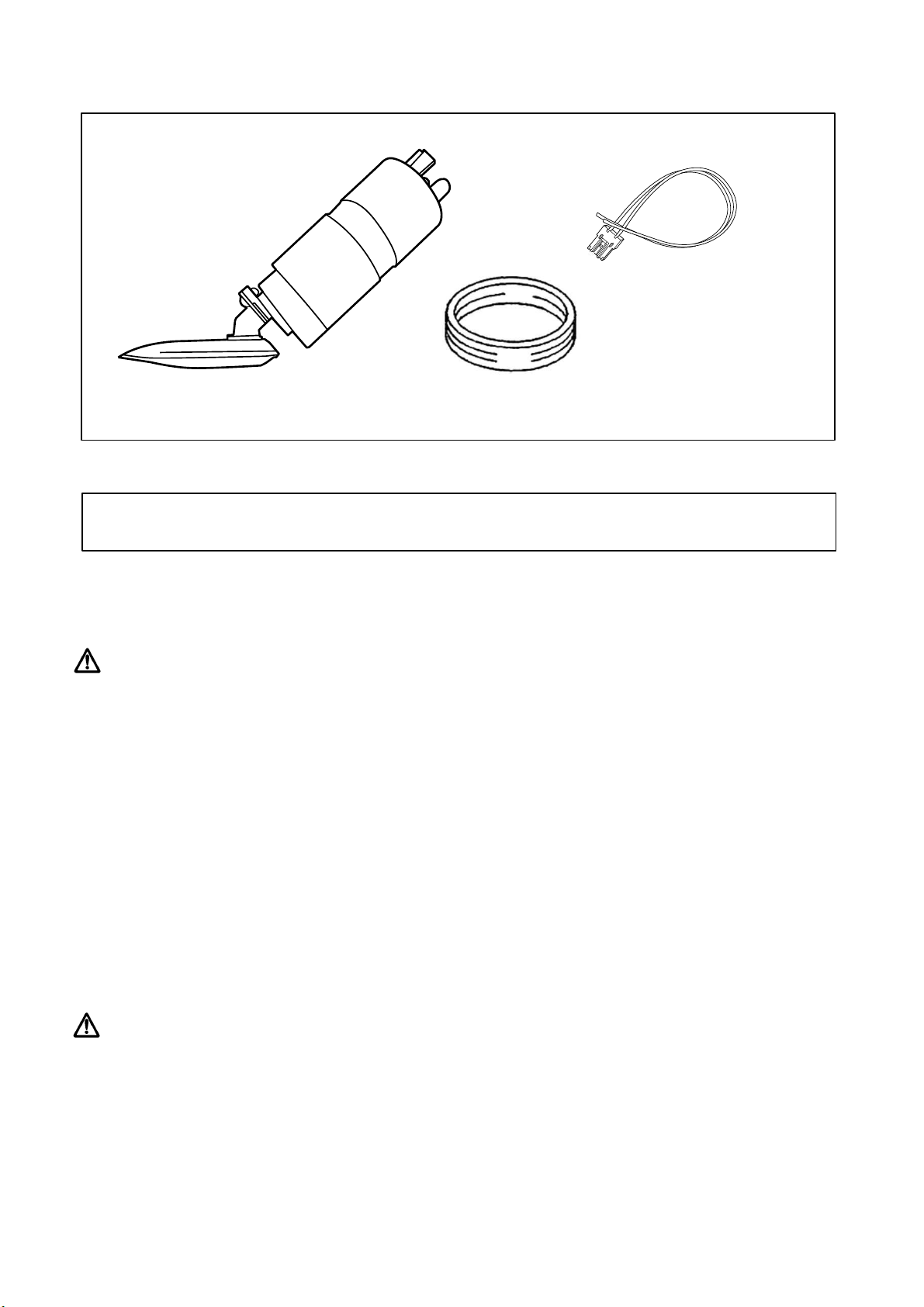
Below is the contents of this kit with the quantity listed in brackets ().
■This product is designed to be used for off road competition purposes only.
■This product must not be used on public roads due to safety risks, and it may not be street legal by local laws.
■This product is to be installed by a qualified professional in a fully equipped workshop.
■Installing this product to any other applications than specified, it may risk damaging this kit, the engine and/or
peripheral components.
■Do not overtighten any bolts/nuts during the installation to avoid the risk of damaging the bolts and/or the product.
■Follow the torque specs as specified in this manual or workshop service manual.
■Inspect every bolt and nut loosened / tightened during the installation regularly after the installation.
■Do not use any excessive force when installing this product as it may risk damaging the product or other parts.
■This product is to be installed with the appropriate tools and equipment to prevent any engine failures, injuries and/or a fire.
■Refer to the vehicles original workshop service manual when disassembling the engine.
■Do not use excessive force when removing and installing parts. As this may cause damage to the parts and related components.
■High flow injectors and a retuned ECU will be required.
■Do not attempt to install the product when the engine and/or the drive train is at operating temperature.
■Please ensure that the installation of the product and the peripheral components is performed accurately.
Failure in the installation may result in damaging the vehicle / product and/or a fire.
KIT CONTENTS
REQUIRED TOOLS
・General Engine Maintenance Tools ・Workshop Service Manual
WARNING
CAUTION
FUEL PUMP (1)
LID SEAL (1)
WIRING HARNESS (1)
7

During the installation, the fuel system will be disconnected resulting in gasoline leakage. Please ensure to
strictly follow the following precautions while performing the installation, or it may pose a risk of explosion or fire.
■
Appropriate environment to perform the installation procedures
① A well-ventilated place.
② There is no tool/equipment that could ignite a fire such as a welder, grinder, electric motor and/or a heater.
③Avoid a place where has a risk of fuel vapor accumulation when performing the installation procedures.
■
Do not use anything that could make a spark or ignite a fire during the installation.
① Any electric tool must not be used for the installation.
・ As a general rule, do not use for this type of job or similar.
・ Do not test the pump and/or fuel in a plastic tank.
・ Do not use a drill, grinder and/or welder.
② Preventing sparks during the installation.
・ Keep your work place spark free. (i.e.. Do not use a hammer).
■
Take measures to prevent static electricity and prioritize safety.
① Have a fire extinguisher readily available near the working space all the time.
② Prevent static electricity.
・ Keep the floor slip free and free from water.
・ Keep the vehicles properly earthed when changing the fuel duct and components.
③ Dispose cloth or towel that contains the fuel carefully and separately from any other waste.
■
Remove as much gas as possible from the gas tank before attempting the installation procedures.
■
Catch as much gas as possible using a cloth or towel that comes out when disconnecting the fuel lines,
not to spill on the floor.
■
Take precautions to prevent debris or any other foreign objects from entering the tank during the
installation.
WARNING Relating to Gasoline
8

Empty the gas tank as much as possible before start the installation.
(1)Removal of the fuel remaining in the fuel lines.
① Remove the fuel pump fuse.
② Remove the fuel filler cap to release the internal pressure from the tank.
③ Let the engine run until it stops by itself, then crank it 3-4 more times to remove the remaining fuel in the lines.
④ Turn the ignition OFF and disconnect the negative terminal of the battery.
(2)Remove the fuel sender unit assembly from the gas tank.
(1)Disassemble the fuel sender unit assembly and remove the
fuel pump assembly from the unit.
The lid seal shown on the left will not be reused.
Use the kit-included Lid Seal when reassemble.
(2)Remove the stock fuel pump body from the fuel pump
assembly, then also the pump cover and the pump bracket.
Everything except the stock pump body will be reused.
1. PREPARATION
2. REMOVAL
This lid seal will not be reused.
Use the new seal came with this kit.
FUEL PUMP ASSY
PUMP COVER
FUEL CHAMBER
FUEL PUMP
PUMP BRACKET
9
(1)Assemble TOMEI Fuel Pump to the pump cover removed from the stock pump body.
Make sure the pump bottom isolator is properly seated to the pump cover.
(2)Attach the pump bracket to the above unit.
(3)Put the assembly back into the fuel chamber.
Make sure that the positioning guide on the back of the pump bracket is properly fitted to the groove on the
fuel chamber side, and the locking tab of the pump bracket are securely locked to the fuel chamber.
(4)Verify the fuel strainer is properly positioned in the bottom of the fuel chamber.
Adjust the position of the pump body if the strainer is not positioned properly.
(5)Cut off the stock wire connector from the vehicle side of the wiring harness and replace with the kit-included
Wiring Harness.
Make sure to connect the positive / negative correctly.
(6)Assemble the fuel sender unit and put everything back in the reverse procedures of removal.
3. INSTALLATION
10
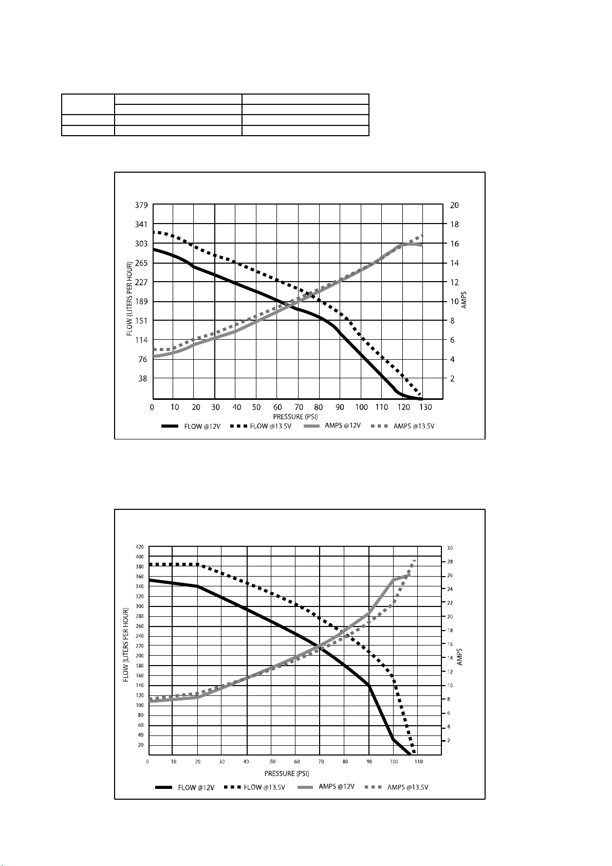
12.0V 215 l/h 300 l/h
183021
183022
Flow Rate(@ 276KPa/40PSI) Flow Rate(@ 276KPa/40PSI)
13.5V 255 l/h 350 l/h
SPECIFICATION
255L/h Fuel Pump Liters Per Hour Flowchart
350L/h Fuel Pump Liters Per Hour Flowchart
11

株式会社 東名パワード
〒
194-0004
東京都町田市鶴間5-4-27
TEL : 042-795-8411(代)
FAX : 042-799-7851
http://www.tomei
-
p.co.jp
大容量フューエルポンプ BNR32 取扱説明書 2023年12月
M18K19
OVER SIZE FUEL PUMP for BNR32 INSTALLATION MANUAL 2023.12 M18K19-0
この製品に関わる取り付け、操作上のご相談は上記へお願いします。
営業時間:月~金(祝祭日、年末年始を除く)9:00~18:00
Please contact your local authorized distributor listed on our website
if you have any questions in regards to the installation / usage of this product.
12
This manual suits for next models
3
Table of contents
Other Tomei Water Pump manuals


