Tone Commander 8610 User manual

13-280116 Rev. C
July 2008
.Tone Commander Systems, Inc.
11609 49th Place West
Mukilteo, WA 98275-4255
(800) 524-0024 (425) 349-1000
Fax (425) 349-1010
www.tonecommander.com
8610 / 8620
ISDN Telephone
Installation
Instructions

Tone Commander 8610/8620 Installation Instructions
Page 2 13-280116 Rev. C
Changes in this revision:
•Stand mounting instructions are clarified.
This manual applies to 8610/8620 software version 01.07.xx
© 2006, Tone Commander Systems, Inc. All rights reserved.
Printed in USA
Tone Commander is a registered trademark of Tone Commander Systems, Inc.

13-280116 Rev. C Page 3
Contents
Introduction.....................................................................................................................................................5
General Features......................................................................................................................................5
Models/Options.........................................................................................................................................5
Controls and Indicators.............................................................................................................................7
Installation.......................................................................................................................................................9
Ordering ISDN Service..............................................................................................................................9
8610T/8620T Installation...........................................................................................................................9
8610U/8620U Installation........................................................................................................................12
Desktop Installation.................................................................................................................................13
Wall Mounting .........................................................................................................................................15
Configure the Set....................................................................................................................................17
Label the Set...........................................................................................................................................18
Installation Options ......................................................................................................................................19
Installation Options Menu .......................................................................................................................19
SPID Entry ..............................................................................................................................................20
Parameter Download ........................................................................................................................... 20
Configuring Keys and Indicators.............................................................................................................21
Terminal Mode........................................................................................................................................26
Installation Password..............................................................................................................................27
Reset to Factory Default Settings...........................................................................................................28
Voice Announce......................................................................................................................................29
Administration Options................................................................................................................................31
Administration Options Menu..................................................................................................................31
Local Inspect...........................................................................................................................................31
Version....................................................................................................................................................34
Test .........................................................................................................................................................35
Diagnostic Display...................................................................................................................................37
Restart.....................................................................................................................................................37
Viewing the Error and Download Logs....................................................................................................37
Troubleshooting............................................................................................................................................39
Inoperable Telephone Recovery Procedures.........................................................................................39
Telephone Configuration Troubleshooting..............................................................................................40
Appendix A Ordering ISDN Service..........................................................................................................41
Recommended Button Assignments.......................................................................................................42
Appendix B Setup Menu Tree...................................................................................................................43
Appendix C Warranty and Service............................................................................................................47
Appendix D Specifications ........................................................................................................................48
Factory Default Settings..........................................................................................................................49
Appendix E UL/FCC Statements ..............................................................................................................50

Tone Commander 8610/8620 Installation Instructions
Page 4 13-280116 Rev. C

13-280116 Rev. C Page 5
Introduction
For operation instructions and user setup options, please refer
to the 8610/8620 User Guide, doc. #14-280195.
General Features _____________________________________________
Tone Commander 8610 and 8620 ISDN Telephones are easy to use multiline terminals with advanced
automatic setup capabilities. S/T and U interface models are available with 10 or 20 call appearances. The
phones support a wide variety of ISDN platforms listed in Appendix D.
Features of the 8610 and 8620 include:
•AutoSPID and Parameter Download •Automatic Switch Type Detection
•Call Log •Message Waiting Indication
•Call Timer •Ringing Control for Shared Lines
•Last Number Redial •Flexible Ringing Options
•Speed Dial •Desktop or Wall Mounting
•Hot Key Dialing •Integrated Speakerphone
•Direct Station Select •Voice Announce
•Call Directory •Handset or Headset Operation
Models/Options ______________________________________________
Several 8600 series ISDN telephone models are available. The models differ in the number of multifunction
keys provided and type of ISDN connection.
The S/T models require an external NT1 Network Termination, such as Tone Commander’s NT1U-223TC
(rack mount) or NT1B-300TC (standalone). Two S/T telephones can share a single ISDN line in a multi-
point arrangement.
U models include a built-in NT1, allowing direct connection to the ISDN line. An additional S/T jack allows
another terminal device to be connected to the network through the built-in NT1.
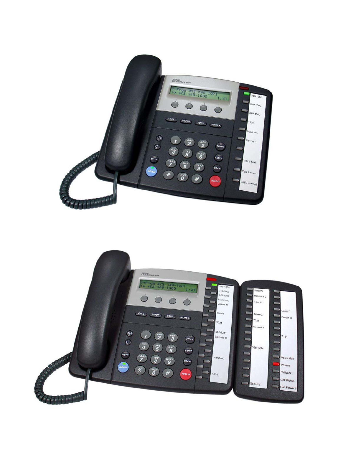
Options include the 8030X Button Expansion Module, which adds 30 multifunction keys to any 8610 or
8620 phone, the 8001TA RS-232 Terminal Adapter for interfacing the phone with any TAPI-compliant
Windows application, the 8002TA Analog Port Terminal Adapter for interfacing with any standard analog
telephone device, and the 8003TA Terminal Adapter, which combines the features of the 8001TA and
8002TA. The 8030X Button Expansion Module can be combined with any of the terminal adapter options.
Basic
Model Multifunction Keys ISDN
Connection
8610T 10 (40 with 8030X) S/T
8620T 20 (50 with 8030X) S/T
8610U 10 (40 with 8030X) U
8620U 20 (50 with 8030X) U
Tone Commander 8610/8620 Installation Instructions
Page 6 13-280116 Rev. C
8610
8620 with 8030X Button Expansion Module
Introduction
13-280116 Rev. C Page 7
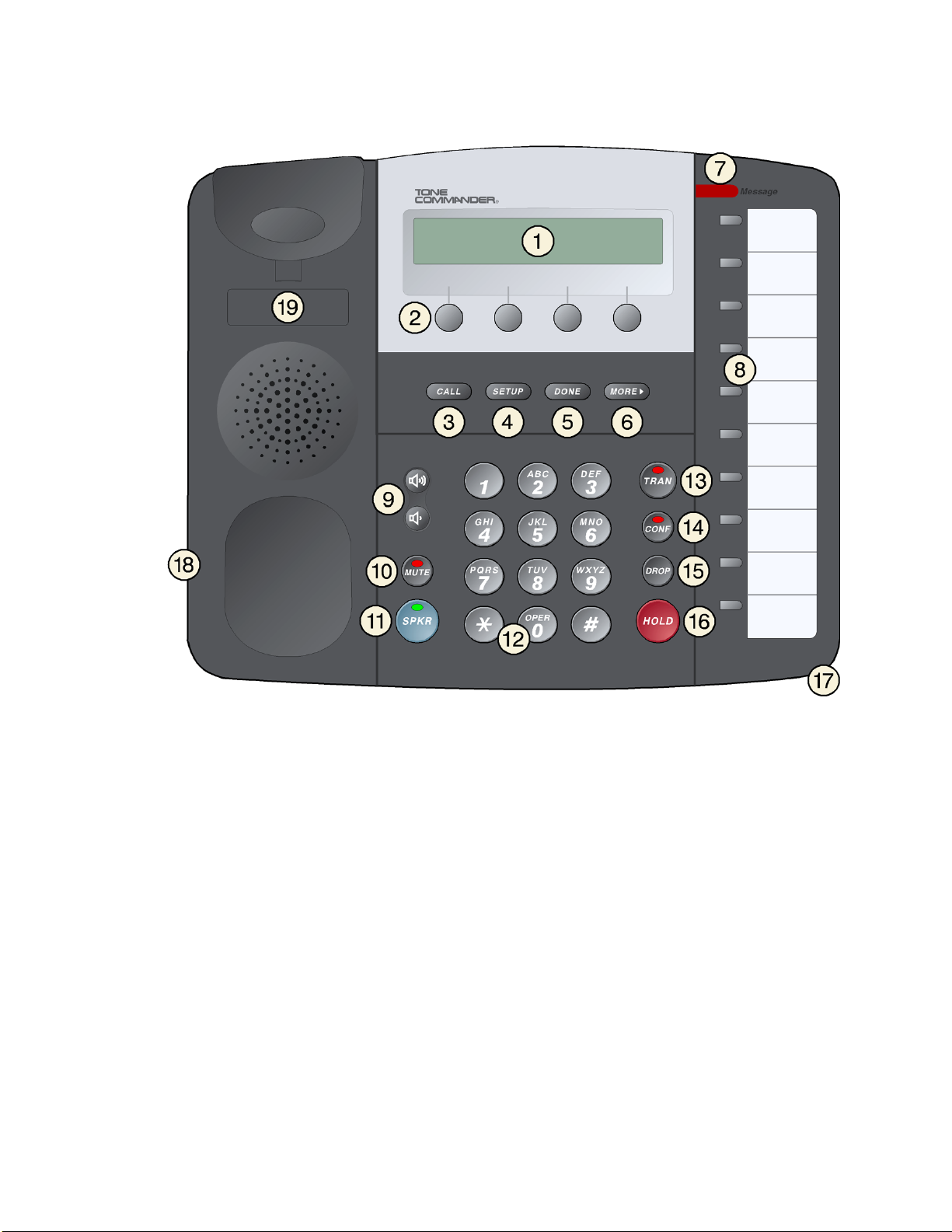
Controls and Indicators _______________________________________
1) Display – shows the call state, caller ID, dialed digits, network call control messages, and elapsed time
during calls. When not on a call, the date, time of day, and softkey options are displayed.
The viewing is primarily set by selecting the high or low base mounting position (page 13). Viewing
angle display clarity can be altered by adjusting the display contrast.
2) Softkeys – select the function displayed above the key on the second line of the display.
3) CALL Key – selects the Call Directory, Call Log, and Call Identification Display modes.
4) SETUP Key – enters Setup Mode.
5) DONE Key – exits the current menu, saves any changes made, and returns to the previous menu
options.
6) MORE4Key – cycles through the menu option groups in Setup Mode.
7) Message Waiting Indicator – a bright red indicator is lit when messages are waiting, controlled by the
network.

Tone Commander 8610/8620 Installation Instructions
Page 8 13-280116 Rev. C
8) Multifunction Keys – select call appearances, activate network features, or dial personal speed dial
numbers. Red and green indicators on the keys show call appearance and feature status. The optional
8030X Button Expansion Module provides 30 additional multifunction keys.
Call Appearance State Indication
Idle OFF
Call Ringing Green – flashing
In Use by You Green – on steady
On Hold by You Green – winking
In Use at Another Terminal
or an Activated Feature Red – on steady
On Hold at Another Terminal Red – winking
9) Volume Keys – adjust the receiver/speaker volume when on a call; adjust the ringer volume when on-
hook.
10) MUTE Key – mutes the microphone when using the speakerphone or handset/headset. A red indicator
on the key is lit when mute is active.
11) SPKR (Speaker) Key – activates the speakerphone. A green indicator on the key is lit when the
speakerphone is in use.
12) Dial Pad – dials telephone numbers, and sends DTMF tones to external equipment such as voice mail
systems. The dial pad is also used for number entry during setup.
13) TRAN (Transfer) Key – places the current call on hold, and selects an idle call appearance for
transferring the call. A second press completes a transfer.
14) CONF (Conference) Key – adds other parties to a conference call.
15) DROP Key – removes the last party added to a conference call, or disconnects you from a call and
returns new dial tone when not in conference mode.
16) HOLD Key – places a call on hold.
17) Microphone – used for hands-free (speakerphone) calling; located in front of the Hold key on the
bottom of the telephone.
18) Handset/Headset Jack – a jack on the side of the telephone connects to the handset or a standard
headset.
19) Telephone Identification Label Area – indented area for a directory number label. Use ½”x 1¾”
adhesive labels (Avery 8167/5267 or equivalent).
13-280116 Rev. C Page 9
Installation
Ordering ISDN Service ________________________________________
ISDN ordering forms may be supplied by your service provider. You can also print forms using the PC-
based Configuration Wizard. Please refer to Appendix A in this manual.
Consult your service provider to plan your service installation. Allow adequate time after cutover for testing
of all call appearances and programmed features. Ask your service provider for your SPID numbers, and
confirm the installation date.
8610T/8620T Installation _______________________________________
S/T models require an external NT1, such as the Tone Commander NT1U-223TC or NT1B-300TC.
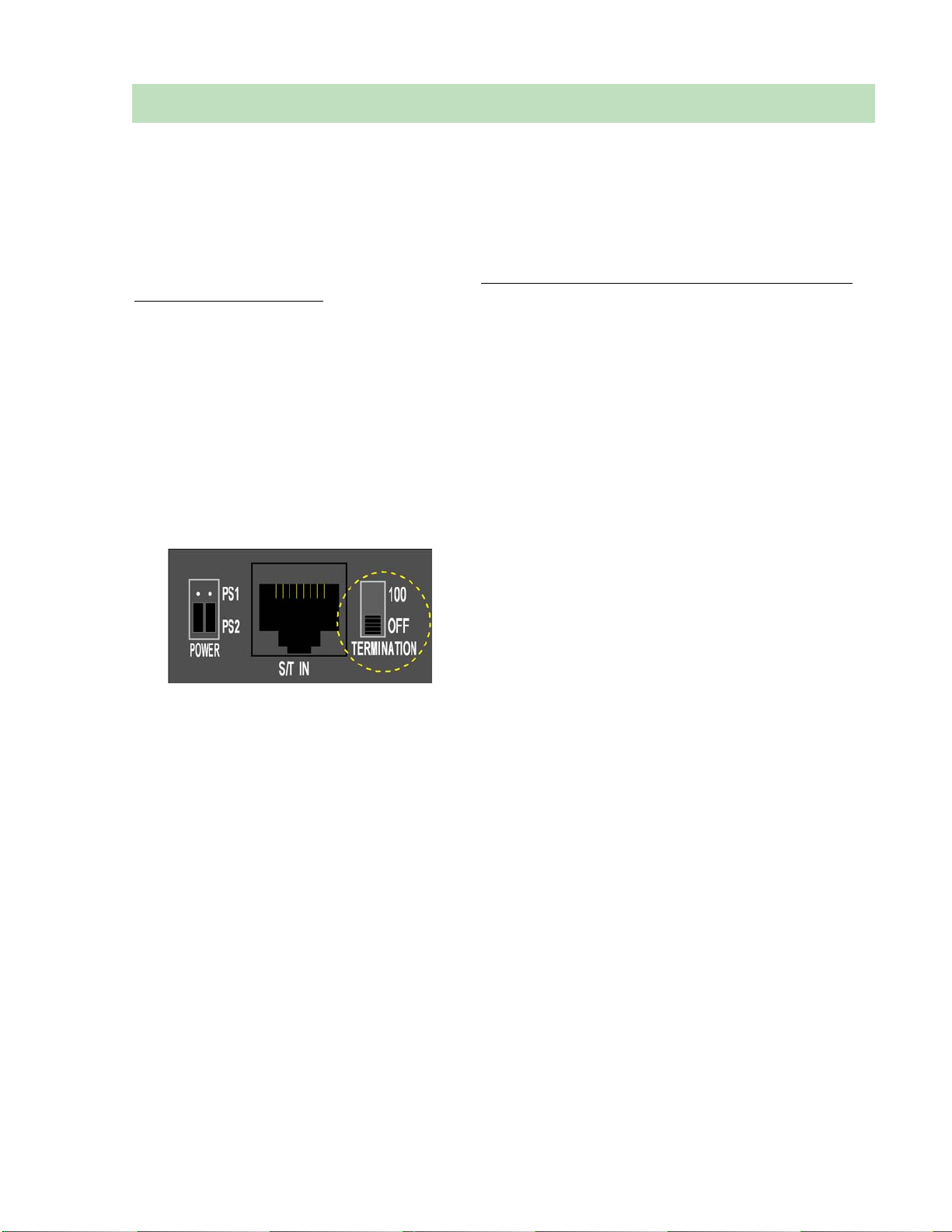
Set the Termination Switches on the Telephone and NT1
Set the termination switches on the bottom of the telephone and on the NT1 to match the termination
impedance to your premises wiring configuration. Several typical wiring configurations are shown below,
with the appropriate switch setting.
We recommend the use of Category 3 or better unshielded twisted pair cable with T568A or T568B
connector wiring. Distances shown are the maximums for 24-gauge cable, and may vary for other cable
types.
Available switch settings are OFF and 100 ohms.
Tone Commander 8610/8620 Installation Instructions
Page 10 13-280116 Rev. C
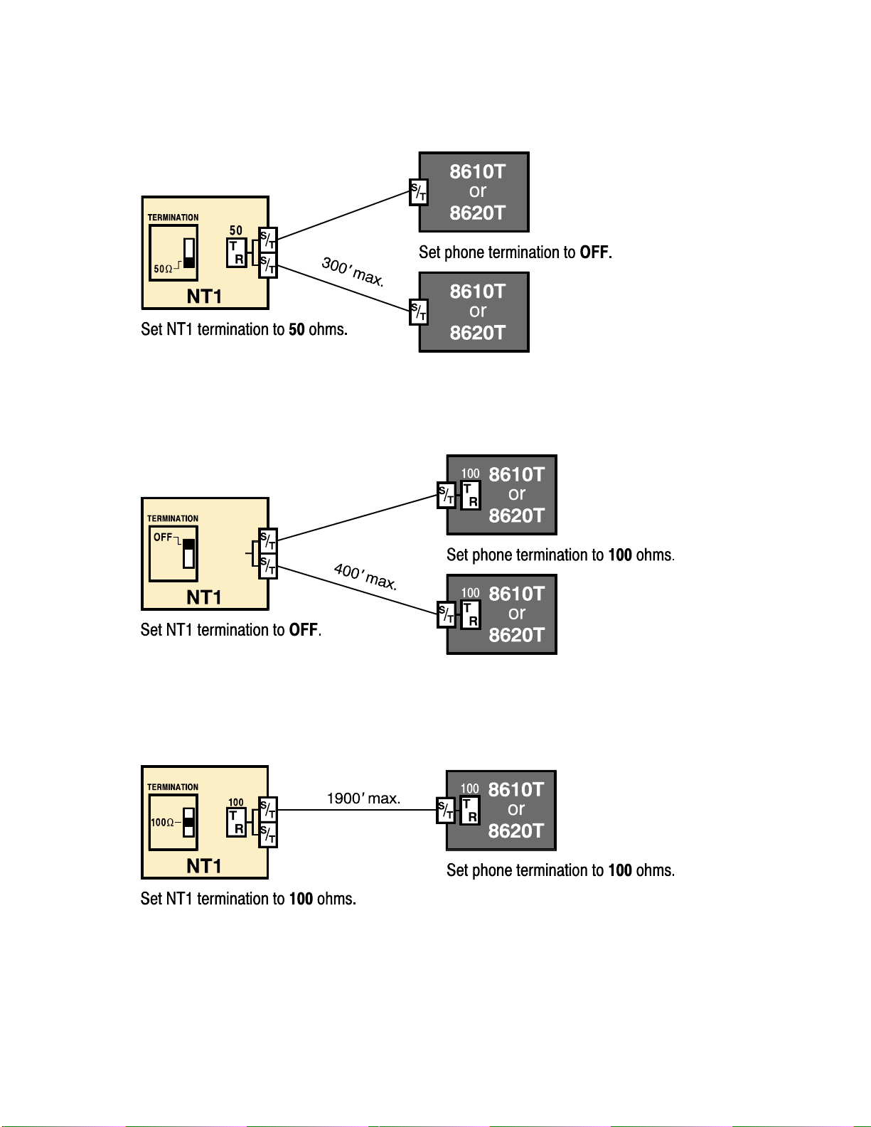
Basic Multipoint:
(recommended for most applications)
Short Multipoint:
Extended Point-to-Point:
Installation
13-280116 Rev. C Page 11
Line and Power Connections
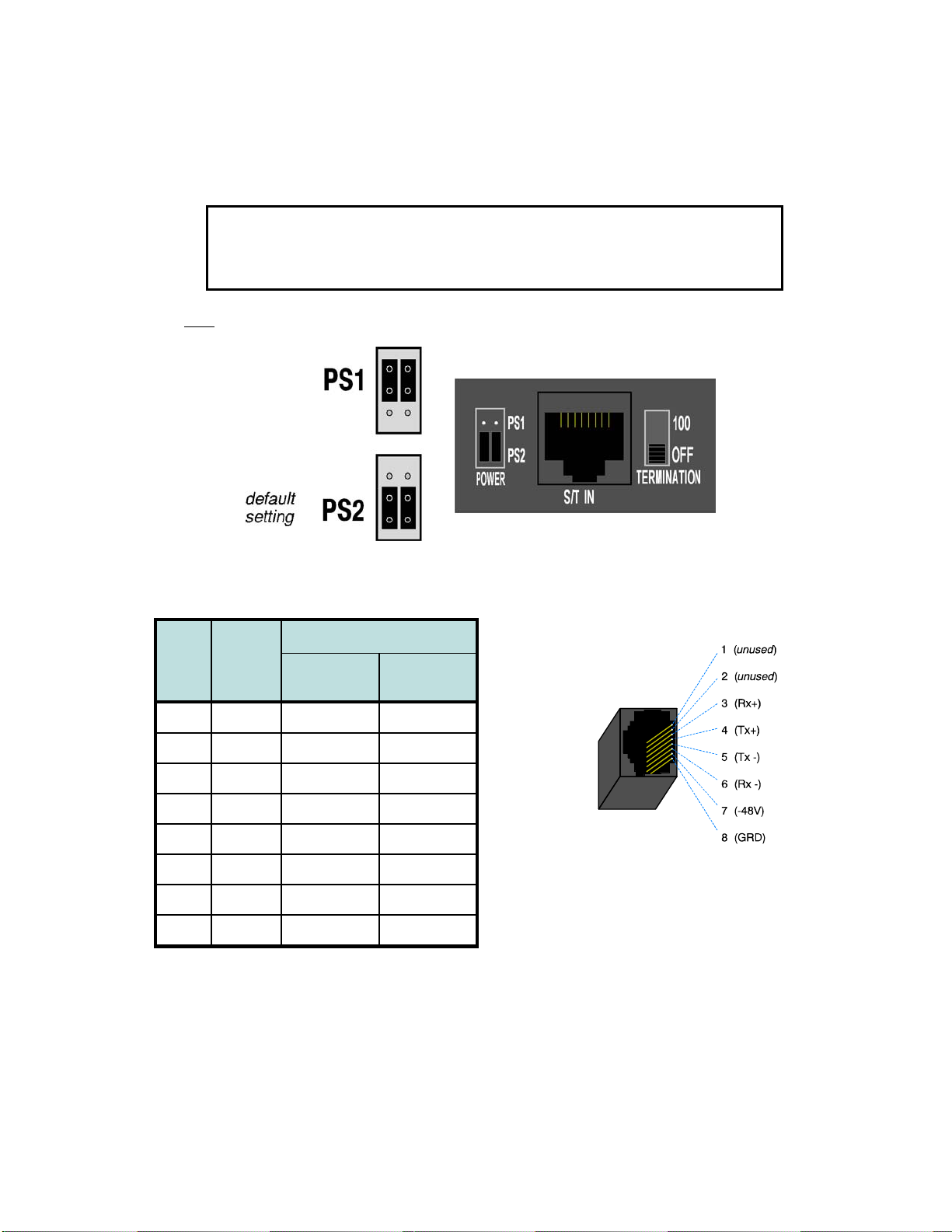
Power for the telephone may be provided on PS1 (phantom power on the transmit and receive pairs from
the NT1) or PS2 (power on pins 7 and 8). Tone Commander manufactures NT1 products that supply power
on both PS1 and PS2. Contact Tone Commander or visit www.tonecommander.com for more
information.
WARNING: If a separate power supply is used to provide PS2 power to the
telephone, make sure that the output ground of the NT1 power supply and the
PS2 power supply are connected (with the correct polarity) to a common ground
reference point or electrical damage to the telephone may occur.
•Set both power jumpers to PS1 or PS2 as required. PS2 powering is used in most applications.
•Using an 8-conductor line cord, connect the S/T IN jack on the telephone to the TERMINAL jack on the
NT1. Route the cord under the guide tabs in the phone base.
Pin # Signal Wire Color
T568 A T568 B
*
(AT&T 258A)
5 Tx- WHT-BLU WHT-BLU
4 Tx+ BLU BLU
1 unused WHT-GRN WHT-ORN
2 unused GRN ORN
3 Rx+ WHT-ORN WHT-GRN
6 Rx- ORN GRN
7 -48V WHT-BRN WHT-BRN
8 GRD BRN BRN
* T568 B jacks are recommended; they allow conventional station pair ordering when connecting to
S/T punchdown blocks on NT1 racks.
Handset/Headset
•Plug the supplied handset or a compatible headset into the jack on the left side of the telephone.
Modular Jack Pinout

Tone Commander 8610/8620 Installation Instructions
Page 12 13-280116 Rev. C
8610U/8620U Installation ______________________________________
U models include a built-in NT1. Optional external ISDN S/T Terminal Equipment may share the
telephone's ISDN line by connecting to the S/T jack on the telephone.
If you are not using external Terminal Equipment, no termination switch setting is required.
Set the Termination Switch on the Telephone
If external Terminal Equipment (TE) is connected, set the termination switch on the bottom of the telephone
to match the termination impedance to your premises wiring configuration. Two typical wiring configurations
for connecting external TE are shown below, with the appropriate switch settings.
We recommend the use of Category 3 or better unshielded twisted pair cable with T568A or T568B
connector wiring. Distances shown are the maximums for 24-gauge cable, and may vary for other cable
types.
Basic Multipoint:
(recommended for most applications)
Extended Point-to-Point:
Available switch settings are 50 and 100 ohms.

Installation
13-280116 Rev. C Page 13
Line and Power Connections
•Using an 8-conductor line cord, connect the U IN jack on the telephone to the line jack.
The 8610U and 8620U can be locally powered by a Tone Commander 901034 Desktop Power Supply.
This may be ordered with a phone as the –PWR1 Option.
•Plug the power supply barrel connector into the round jack on the back of the phone.
•When all other connections are completed, connect the power supply to a standard 120 VAC, 60 Hz
grounded power outlet.
Power can also be provided by an external -48 VDC source, such as a Tone Commander PS-50 ISDN
Power Supply, on pin 7 (-) and pin 8 (+) of the U IN jack.
Select only one powering method; DO NOT connect the local power supply and
power over the line cord simultaneously!
An additional terminal may be connected to the S/T OUT jack, which supplies PS1 and PS2 output power.
Handset/Headset
•Plug the supplied handset or a compatible headset into the jack on the left side of the telephone.
Desktop Installation __________________________________________
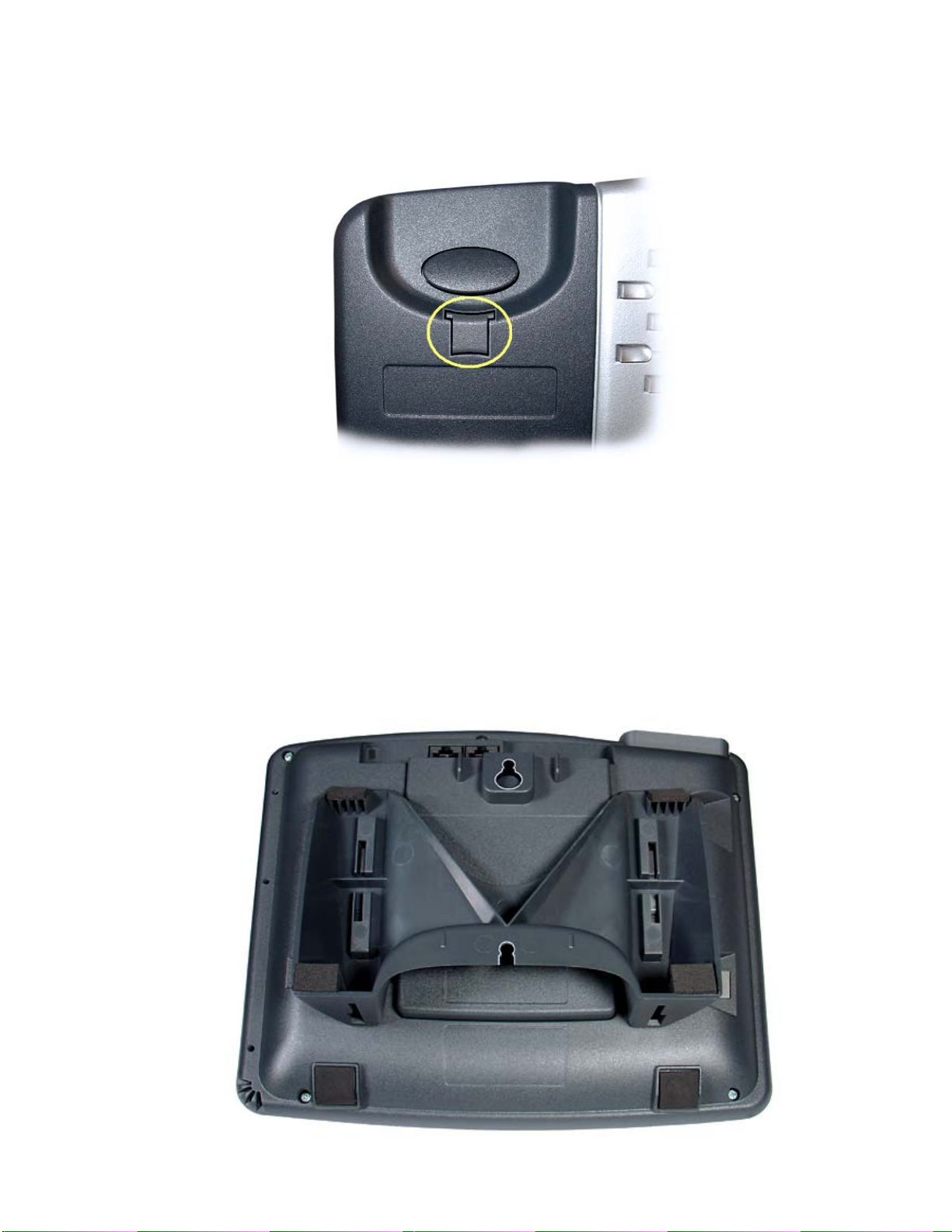
The stand can be installed in two positions for desktop use. Select the position that provides the best
screen readability and easy control operation for the phone’s location.
•If you need to remove the stand, press it down to disengage the snap tabs, and then lift off the stand.
The low desktop stand position is shown; the removal procedure is the same for high desktop and wall
mount positions.
Stand Removal

Tone Commander 8610/8620 Installation Instructions
Page 14 13-280116 Rev. C
•Rotate the stand as needed; refer to the pictures below.
•To install the stand, insert the tabs on the telephone into the large openings in the stand’s upper slots,
and then press the stand toward the top of the telephone until it locks into place.
If you are installing an 8030X Button Expansion Module on the phone, use the double-width stand
included with the 8030X.
Low Desktop Position
High Desktop Position
Installation
13-280116 Rev. C Page 15
Handset Retainer Clip, Low Desktop Applications
For low desktop position use, the handset retainer clip should be installed in the default position, without
the tab protruding into the hookswitch area. Rotate the clip for high desktop applications – see page 16.
Wall Mounting _______________________________________________
The phone stand and handset retainer clip must be rotated for wall mounting.
•Remove the stand from the phone base – see page 13.
•Rotate the stand as shown below.
•To install the stand, insert the tabs on the telephone into the large openings in the stand’s upper slots,
and then press the stand toward the top of the telephone until it locks into place.

Tone Commander 8610/8620 Installation Instructions
Page 16 13-280116 Rev. C
Attaching to a wall mount jack
•Plug an 8”, 8-pin line cord into the S/T IN jack (8610/8620T) or the U IN jack (8610U/8620U) on the
telephone. If you do not have one, you can obtain an 8” line cord by calling Tone Commander Technical
Support at (800) 524-0024.
•Hold the telephone next to the wall mount jack. Plug the line cord into the jack.
•Hang the telephone on the wall plate mounting studs. The top mounting stud fits into the keyhole slot in
the phone expansion cover or optional Terminal Adapter, and the bottom stud slides into the ‘U’-shaped
slot in the wedge base. Press down firmly to lock into place.
Handset Retainer Clip, Wall Mount or High Desktop Position Applications
Pull out the handset retainer clip as shown. Rotate the clip 180°, and then re-insert the clip. The tab should
protrude into the hookswitch area for wall mount or high desktop position use

Installation
13-280116 Rev. C Page 17
Configure the Set ____________________________________________
ISDN configuration is performed automatically in many cases. The telephone set will detect the switch type,
set the SPID number, and download other setup parameters when these features are available from the
Telco central office.
You will be prompted for any required setup information that cannot be set automatically.
Initialization
A self-test is performed upon power up. Press any key to begin initialization with the network. Unattended
initialization begins automatically after a short random time interval. This delay prevents multiple terminals
at a site from initializing simultaneously after a power outage.
The display will show progress while establishing the communication layers. When all three communication
layers are established, the TEI (Terminal Endpoint Identifier) and switch type will be shown for two
seconds.
SPID Entry
The SPID number will be assigned automatically if the network supports AutoSPID. If there is more than
one SPID available for your terminal, you will be prompted to select your primary telephone number.
If AutoSPID is not supported, you will be prompted to enter the phone’s primary telephone number, which
is used by the phone to generate a SPID number. Enter the number with the dial pad, and then press the
DONE key.
Å
BKSP (backspace) deletes the previous digit.
National ISDN – enter your full 10-digit telephone number
(including area code)
5ESS Custom ISDN – enter your 7-digit telephone number
Parameter Download (National ISDN only)
Parameter Download is a network feature that Identifies Call Appearance and Feature Activator keys that
are assigned to your line so that your phone may be configured automatically.
Note: Speed Dial, DSS keys, and other user preference settings are not configured by Parameter
Download.
If Parameter Download is not supported, the following screen may appear momentarily, prompting you to
manually configure the telephone at a later time (see page 20).
Automatic Button Detection (5ESS Custom ISDN only)
Press each multifunction key. The phone will discover the key's network assignment. Keys that have no
network assignment may be used for speed dialing – please refer to page 24.
L1:OK L2:OK TEI:123
L3:OK SWITCH=5ESS NI-X
ENTER PRIMARY PHONE #
999-555-1243 ←BKSP
NO PARAMETER DOWNLOAD
PRESS SETUP TO CONFIGURE

Tone Commander 8610/8620 Installation Instructions
Page 18 13-280116 Rev. C
Firmware Updates
Call Tone Commander technical support at (800) 524-0024 to get information on firmware updates.
Using Local Inspect to Verify Keys
Local Inspect allows you to identify the call appearance or feature assignment of each configured key,
directory number bearer capabilities, and the feature indicator assignment for the Message Waiting
Indicator. Please refer to page 31.
Label the Set ________________________________________________
Label the multifunction keys with the telephone number, feature name, speed dial party name, or other
appropriate designation. A perforated label sheet is provided with the telephone.
The 8610/8620/8810 User Setup Program allows you to set up key labels, Speed Dial keys, Voice Mail
Menu keys, and the Call Directory using a Windows PC interface. The phone setup information can be read
from the phone, saved to disk, and loaded into an 8610, 8620, or 8810 telephone that is equipped with an
8001TA or 8003TA Terminal Adapter. The program will also print key labels for the 8030X Button
Expansion Module and 8610/8620 telephones. You can download this program from
www.tonecommander.com; please refer to Appendix A on page 41.
Install the key label overlays by inserting the tabs into the openings on the phone.
A space is provided beneath the handset for a directory number label. Use ½”x 1¾”adhesive labels
(Avery 8167/5267 or equivalent).

13-280116 Rev. C Page 19
Installation Options
Options in this section are typically set at the time of installation. Many options can be set automatically by
the AutoSPID, Automatic Switch Detect, and Parameter Download features, if supported on the network.
The following options can be changed from the Installation Options menu:
•SPID
•
Installation Password
•Parameter Download
•
Reset to Default Settings
•Terminal Mode
•
Voice Announce
•Keys and Indicators
Installation Options Menu _____________________________________
You can enter the Installation Options menu when the phone is idle.
Press the SETUP key.
Select INSTL.
When Æappears in the top line of the display, you can press the MORE4key to see additional
menu selections.
Note: The POTS option is only available when the 8002TA or 8003TA Analog Port Terminal Adapter is
installed.
The PARAM and MODE options are only available with National ISDN.
A password may be set to prevent unauthorized entry into the Installation Options menu.
When prompted for a password, enter your password with the dial pad. Press the DONE
key after entering the password.
To change or remove the password, please refer to page 27.
SETUP MENU
INSTL ADMIN USER POTS
INSTALLATION OPTIONS →
SPID PARAM KEYS MSG
INSTALLATION OPTIONS →
MODE PASSWD RESET VA

Tone Commander 8610/8620 Installation Instructions
Page 20 13-280116 Rev. C
SPID Entry __________________________________________________
A unique SPID (Service Profile IDentifier) is required for operation of the 8610/8620. If the network
supports AutoSPID, a SPID that is assigned to your ISDN line can be automatically selected. If National
ISDN generic SPID assignments are used by your service provider, your SPID will consist of your primary
telephone number followed by “0101” (e.g., 42534910000101). Contact your network service provider for
your telephone’s SPID.
From the Installation Options menu, select SPID.
(SETUP →INSTL →SPID)
Using the dial pad, enter the SPID number supplied by your network service provider.
If you need to make corrections, select
Å
BKSP (backspace) to delete the previous digit.
CLEAR removes all digits, allowing you to start over.
When digits have been entered, press the DONE key to return to the Installation Options menu or
press the SETUP key to exit Setup Mode.
Parameter Download _________________________________________
(National ISDN only)
ISDN Parameter Download is an automated feature for configuring Call Appearance and Feature Activator
keys. If configured for auto download, a Parameter Download is executed when the phone initializes with a
new SPID, or when requested by the network, due to a line configuration change.
Note: Speed Dial and DSS keys are not configured by Parameter Download.
From the Installation Options menu, select PARAM.
(SETUP →INSTL →PARAM)
Starting a Download
Select START to manually initiate a Parameter Download.
Enabling/Disabling Automatic Download
Select AUTO.
Select ENABLE or DISABLE.
ID=42534910000101
←BKSP CLEAR
PARAMETER DOWNLOAD
START AUTO
AUTO DOWNLOAD=ENABLED
ENABLE DISABLE
Other manuals for 8610
2
This manual suits for next models
1
Table of contents
Other Tone Commander Telephone manuals

Tone Commander
Tone Commander 8810 User manual

Tone Commander
Tone Commander 6220T-TSG User manual

Tone Commander
Tone Commander 524 User manual

Tone Commander
Tone Commander 2260d User manual

Tone Commander
Tone Commander 30e120 User manual

Tone Commander
Tone Commander 1030 User manual

Tone Commander
Tone Commander 8610 User manual

Tone Commander
Tone Commander 524 User manual

Tone Commander
Tone Commander 6210 User manual

Tone Commander
Tone Commander 6220-TSG-DD User manual


