MALUX ExResistTel Operating instructions

Art. Nummer. : 112 861 01
Part No. Ersatzteil Beschreibung Spare part description
9700U003A000-LG Handapparat komplett mit Panzerschnur Handset complete with armoured cord
112 861 08 Panzerschnur komplett 1m Handset cord 1m
112 861 09 Panzerschnur komplett 2m Handset cord 2m
112 861 10 Panzerschnur komplett 3m Handset cord 3m
112 861 11 Panzerschnur komplett 5m Handset cord 5m
9700U600A020-LG Gehäuseoberschale mit Tastatur Cover plate incuding keypad
9701U500A000-LG Einsatz mit Gehäuseunterschale PCB including bottom part
584360030 Lautsprecher Speaker
W49088A315 Display Display
9700U007A000-LG Freisprecheinrichtung Handsfree microphone
519670083 Hörkapsel Hearing capsule
9700U008A000-LG Mikrofon komplett Microphone complete
9700U530A00 Rasthakenset Snaphookset
FHF Funke+Huster Fernsig GmbH · Postfach 14 01 66 · D-45441 Mülheim an der Ruhr · Gewerbeallee 15-19
D-45478 Mülheim an der Ruhr · Telefon +49-208-82 68-0 · Telefax +49-208- 82 68-286 · http://www.fhf.de · e-mail: [email protected]
Ersatzteilliste explosionsgeschützter Fernsprecher Ex ResistTel
Spare parts exploison proof phone Ex Resistel
MaluxD

No.:
Repair of ex equipment Index:
0
Repair manual
Repair manual
Example: ResistTel and ExResistTel Rev.: 0 Page 1 of 15
Repair manual
No.: Repair of ex equipment Index: 0 18.05.2010
Title: Repair instructions for ResistTel and ExResistTel
Foreword to the repair manual for ex equipment
•here using the example of ResistTel and the ExResistTel
Work on the equipment must be carried out by specialist personnel (qualified person).
In accordance with the technical rules for operating safety TRBS 1203 part 1, the qualified person
must fulfil the requirements for the explosion protection tests in accordance with paragraph 2.1
(professional training), paragraph 2.2 (professional experience) and paragraph 2.3 (recent
professional activity).
In accordance with the ordinance on industrial safety and health (BetrSichV) §6, the employer
(and thus also the qualified person) have to ensure that an explosion protection document is drawn
up and kept up to date.
The explosion protection document is to be drawn up before work is commenced. It is to be revised if
changes, extensions or transformations of the work equipment or work process are carried out.
Any repair or exchange must be carried out in a clean environment and in a workshop atmosphere.
Any repair or exchange of components must be carried out in de-energised state - the equipment is
to be disconnected from the mains.
The instructions for opening/closing the equipment must be followed exactly as they are given in the
repair manual.
To finish off the repair, the operator or the qualified person from his enterprise must carry out an
appropriate test (e.g. a high voltage test) on the equipment.
If parts are not repaired/exchanged appropriately, the guarantee liability of the manufacturer expires.
If exchanging part of a piece of equipment for an original spare part, the legal guarantee period only
begins for this spare part. No new guarantee begins for the entire equipment.
If performing one of the aforementioned measures, it is assumed that the operator is familiar with the
associated documentation and uses it correctly.

No.:
Repair of ex equipment Index:
0
Repair manual
Repair manual
Example: ResistTel and ExResistTel Rev.: 0 Page 1 of 15
Funke+Huster Fernsig GmbH
Gewerbeallee 15-19
D-45478 Mülheim an der Ruhr
http://www.fhf.de e-mail:
Phone +49/208/8268-0
Contents
1.
Exchange of upper part of telephone….…….…. Page 3,4
2.
Exchange of lower part of telephone….….….…. Page 5,6
3.
Exchange of handset….….….….….….….….…. Page 7, 8, 9, 10
4.
Exchange of display….…….….….…….….….… Page 11, 12, 13,14
5.
Exchange of receiver hook for handset….…….… Page 15

No.:
Repair of ex equipment Index:
0
Repair manual
Repair manual
Example: ResistTel and ExResistTel Rev.: 0 Page 1 of 15
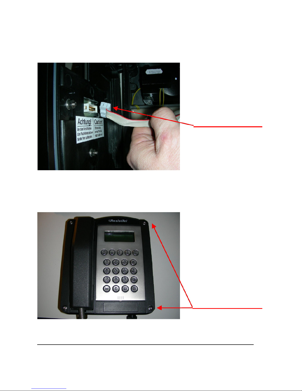
1. Exchange of upper part of telephone
Loosen 4 cover screws
with torx key TX 30.
Screws are
captive.
Carefully remove upper part
of telephone
(no strain may be put on
the flat connector).
Note: Detach flat connector
in the upper part of the
telephone leading to the
electronics in the lower part
of the telephone and remove
upper part of the telephone

No.:
Repair of ex equipment Index:
0
Repair manual
Repair manual
Example: ResistTel and ExResistTel Rev.: 0 Page 1 of 15
Attach new telephone
upper part to existing flat
connector of the lower
part of the telephone.
The plug connection is
restraint-guided via a
tongue and groove.
Put upper part of telephone
onto the lower part of the
telephone and fasten with 4
cover screws (torque 3Nm,
key TX30)
Note:
Do not tilt the upper
part of the telephone.
Screw on the screws evenly
and crosswise. Consider
position of the seal.
Perform a visual and functional check after assembling the equipment.

No.:
Repair of ex equipment Index:
0
Repair manual
Repair manual
Example: ResistTel and ExResistTel Rev.: 0 Page 1 of 15
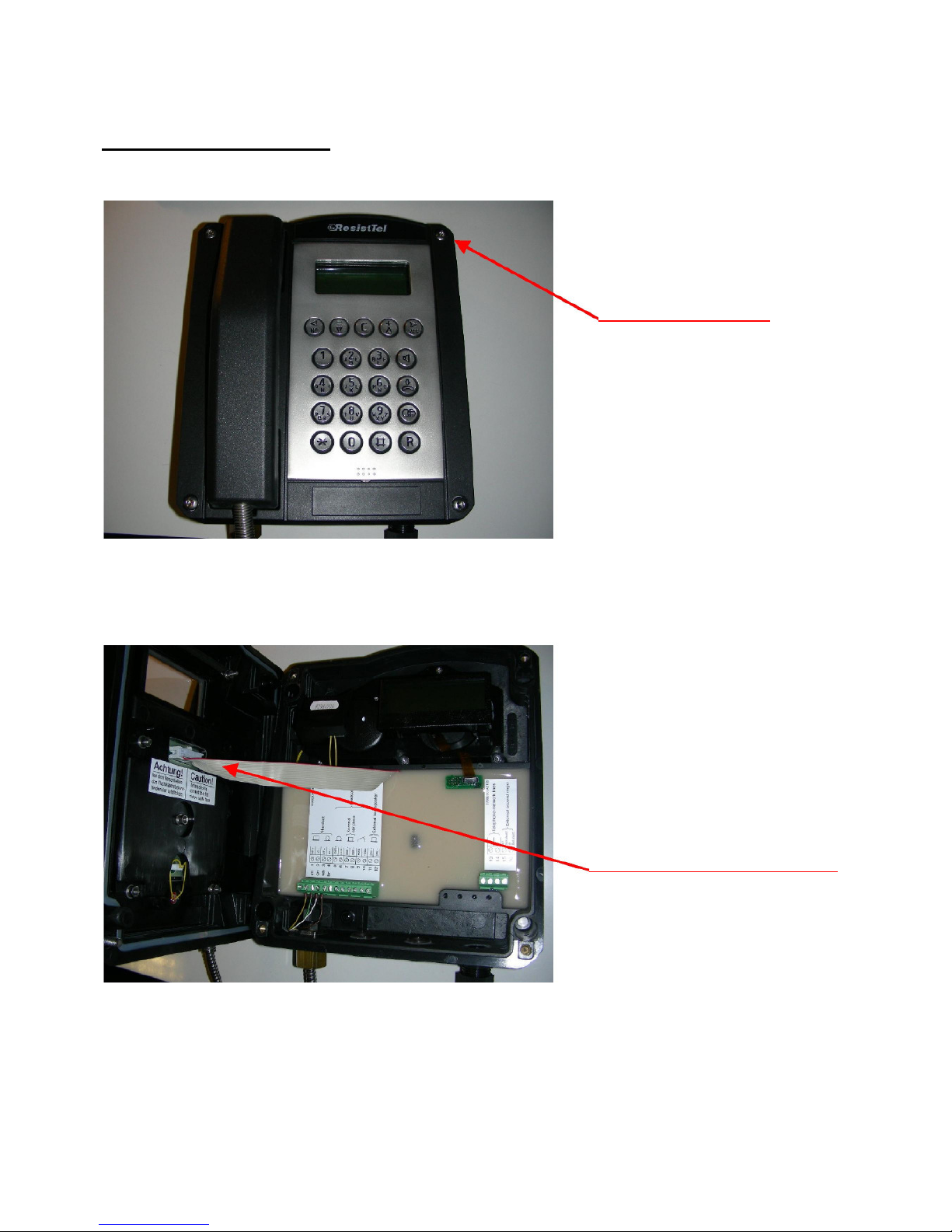
Carefully
remove upper part of
telephone
(
no strain may be put on the
flat connector
).
Note: Detach flat connector
in the upper part of the
telephone leading to the
electronics in the lower part
of the telephone and remove
upper part of the telephone
2. Exchange of lower part of telephone
Loosen 4 cover screws with
torx key TX30.
Screws are captive.
No.:
Repair of ex equipment Index:
0
Repair manual
Repair manual
Example: ResistTel and ExResistTel Rev.: 0 Page 1 of 15
Attach new housing lower
part with attached flat
connector to the upper part
of the telephone. The plug
connection is restraint-
guided via a tongue and
groove.
Put upper part of
telephone onto lower
part of telephone and
fasten with 4 cover
screws (torque 3Nm,
key TX30)
Note:
Do not tilt the upper part
of the telephone and
screw on the screws
evenly and crosswise.
Consider position of the
seal.
Perform a visual and functional check after assembling the equipment
No.:
Repair of ex equipment Index:
0
Repair manual
Repair manual
Example: ResistTel and ExResistTel Rev.: 0 Page 1 of 15
3. Exchange of handset
Loosen 4 cover screws
with torx key TX 30.
Screws are
captive.
Carefully remove upper part
of telephone
(no strain may be put on
the flat connector).
Note: Detach flat connector in
the upper part of the telephone
leading to the electronics in the
lower part of the telephone and
remove upper part of the
telephone

No.:
Repair of ex equipment Index:
0
Repair manual
Repair manual
Example: ResistTel and ExResistTel Rev.: 0 Page 1 of 15
Remove receiver complete
with armoured cord
.
Disconnect connecting
wires (4 pcs) with suitable
tools.
Loosen nut with M24 jaw
spanner and remove.

No.:
Repair of ex equipment Index:
0
Repair manual
Repair manual
Example: ResistTel and ExResistTel Rev.: 0 Page 1 of 15
Push the connecting cord of the
new receiver through.
Note:
Ensure anti-twist protection
(hexagon) in the housing.
The brass hexagon must
penetrate into the housing.
Attach connecting wires in
accordance with the colour
coding on the stick-in sign
using suitable tools
Attach counternut and fasten
with M24 jaw spanner.

No.:
Repair of ex equipment Index:
0
Repair manual
Repair manual
Example: ResistTel and ExResistTel Rev.: 0 Page 1 of 15
Attach upper part of
telephone. The plug
connection is restraint-
guided via a tongue
and groove.
obligation
-
led.
Put upper part of
telephone onto lower
part of telephone and
fasten with 4 cover
screws (torque 3Nm,
key TX30)
Note:
Do not tilt the upper part
of the telephone and
screw on the screws
evenly and crosswise.
Consider position of the
seal.
Perform a visual and functional check after assembling the equipment.

No.:
Repair of ex equipment Index:
0
Repair manual
Repair manual
Example: ResistTel and ExResistTel Rev.: 0 Page 1 of 15
Carefully
remove upper part
of telephone
(no strain may be put on
the flat connector).
Note: Detach flat connector
in the upper part of the
telephone leading to the
electronics in the lower part
of the telephone and remove
upper part of the telephone
4. Exchange of display
Loosen 4 cover screws with
torx key TX 30.
Screws are captive.

No.:
Repair of ex equipment Index:
0
Repair manual
Repair manual
Example: ResistTel and ExResistTel Rev.: 0 Page 1 of 15
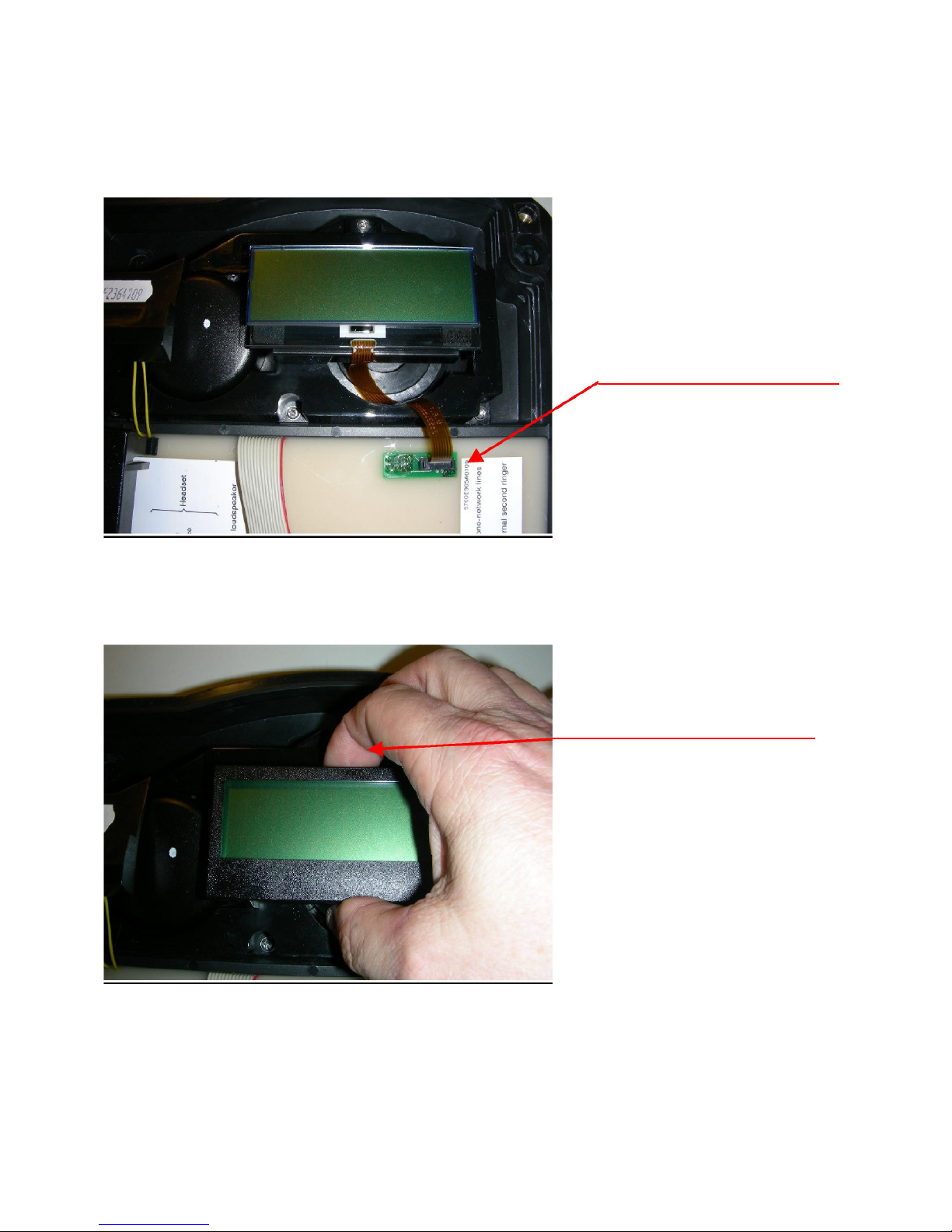
Carefully remove display
frame by pressing the
receiver hook at the back.
Loosen the connecting line by
unlocking the zero insertion
force connector and remove
the display
No.:
Repair of ex equipment Index:
0
Repair manual
Repair manual
Example: ResistTel and ExResistTel Rev.: 0 Page 1 of 15
Place the new display in the
centre of the mounting frame.
Attach connecting line to zero
insertion force connector and
lock.
Put display frame up
straight and press down
until the receiver hook at
the back locks in place.

No.:
Repair of ex equipment Index:
0
Repair manual
Repair manual
Example: ResistTel and ExResistTel Rev.: 0 Page 1 of 15
Put upper part of
telephone onto lower
part of housing and
fasten with 4 cover
screws (torque 3Nm,
wrench TX30)
Note:
Do not tilt the upper part
of the telephone and
screw on the screws
evenly and crosswise.
Consider position of the
seal.
Attach upper part of
telephone. The plug
connection is restraint-
guided via a tongue
and groove.
Perform a visual and functional check after assembling the equipment.

No.:
Repair of ex equipment Index:
0
Repair manual
Repair manual
Example: ResistTel and ExResistTel Rev.: 0 Page 1 of 15
Screw in receiver hook
with metal spring into the
bottom of the telephone
upper part.
5. Exchange of receiver hook for handset
Remove handset
from the upper part
of the telephone.
Loosen screws for
fastening the receiver
hook using a key Tx20.
Remove receiver hooks
on both sides of the
telephone upper part.
Insert new receiver
hooks.
Note:
Push receiver hooks
outwards as far as
they will go and screw
them on. (torque 3Nm,
key Tx20)
Note:
The retention force
of the receiver can
be continuously
adjusted. Pushing
the receiver hooks
together
strengthens the
retention force
whilst pulling them
apart decreases it.
Perform a visual and functional check after assembling the equipment
This manual suits for next models
1
Table of contents
Other MALUX Telephone manuals


