Toner DIP3200A User manual

DIP3200A 32 Program IP to Analog Modulator
User Manual
969 Horsham Road lHorsham, Pennsylvania 19044 USA l Phone: 215-675-2053 Fax: 215-675-7543 l[email protected]

Directory
Chapter 1 Product Overview ..............................................................................1
1.1 Key Features..................................................................................................1
1.2 Specifications............................................................................................ 1-2
1.3 Appearance and Illustration .........................................................................3
Chapter 2 Installation Guide...............................................................................4
Chapter 3 Web NMS Management ............................................................... 5-12
Precautions........................................................................................................13
1
Chapter 1 Product Overview
1.1 Key Features
2 GE ports (max 64 IP programs total MPTS/SPTS), Max 840Mbps for each GE input
Support HEVC/H.265, H.264/AVC, MPEG-2 TS Decapsulation
Processing of up to 32 IP multicast groups of a Gigabit Ethernet MPEG TS into up to 32
standard NTSC or PAL Analog channels
32 non-adjacent or adjacent carriers output within 400MHz bandwidth
RJ-45 Ethernet front jack for Configuration and Web-based Network management
1.2 Specifications
Input
Interface/rate
2 GE RJ-45 ports for content ingest
Max 840Mbps for each GE input
Stream
UDP, UDP / RTP, 1-7 packets, FEC, SPTS,
MPTS
Transport Protocol
UDP/RTP, unicast and multicast, IGMP
V2/V3
Packet Length
188 / 204 Bytes
Decoding
Parameters
Video codecs
HEVC/H.265, H.264/AVC Level 4.1 HP,
MPEG-2 MP@HL
Audio formats supported
MPEG-1/2 Layer 1/2, (HE-)AAC,AC3
Data
Teletext, Teletext subtitles, DVB Subtitling
Resolutions
HEVC/H.265:
1080@60P ,1080@60I,1080@50P,1080@
50I,720@60P,720@50P

2
H.264/AVC:
1080@60I,1080@50P,1080@50I,1080@3
0P,1080@25P ,
720@60P,720@50P,576@50I,480@60I
MPEG2:
1080@60I,1080@50I,
720@60P,720@50P,576@50I,480@60I
Aspect ratio
4:3/16:9
Modulation
Number of Output
Channels
Up to 32 Analog
Connectors
75 ohm F-Female
Frequency range
47 – 862MHz
Output Bandwidth
400MHz
Output level
maximum 52 dBmV
Return loss
≥ 14dB
Spurious frequency dist.
≥ 60dB
Stereo cross talk
> 55dB
Residual carrier
accuracy
1%
TV standard
NTSC or PAL B-G,
Video-signal to noise
ratio
≥ 60dB
Network
Interface
Management
1 x 100 Base-T Ethernet (RJ 45)
Data
2 x 1000 Base-T Ethernet (RJ 45)
Protocol
IEEE802.3 Ethernet, RTP, ARP, IPv4,
TCP/UDP, HTTP, IGMPv2/v3
Performance
Image resolution
up to 1080i
CNR
60 dB (after internal combining)
SNR
> 53 dB (after internal combining)
Sampling frequency
48, 44.1, 32
Output volume
adjustment
0 - 100 %
General
Demission
19x16.5x1.75 Inches 420×440×44.5
(WxDxH)
Temperature
32-110 °F (0-45° C)
Power Supply
AC100V±10%, 50/60Hz
or AC 220V±10%,50/60Hz
3
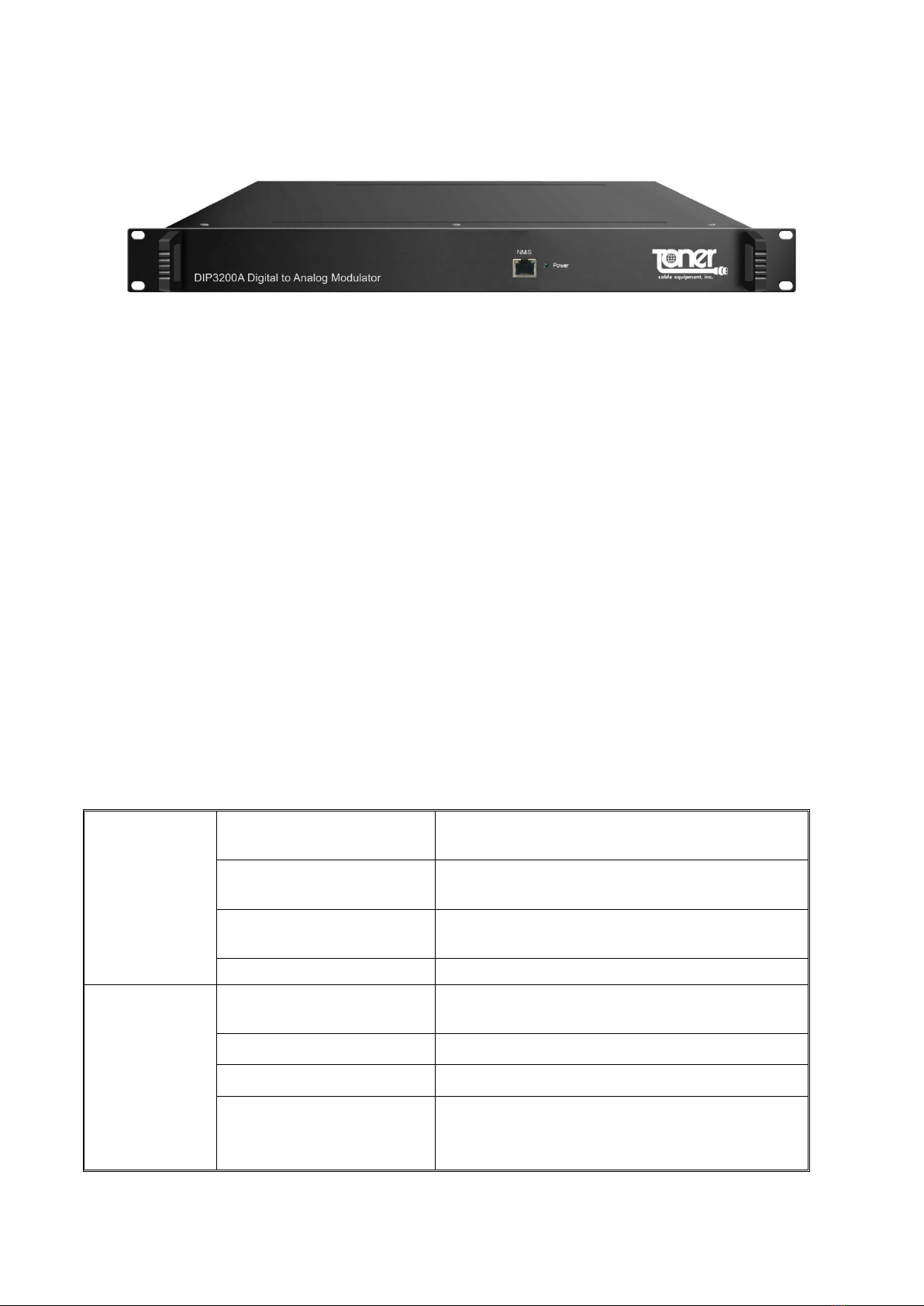
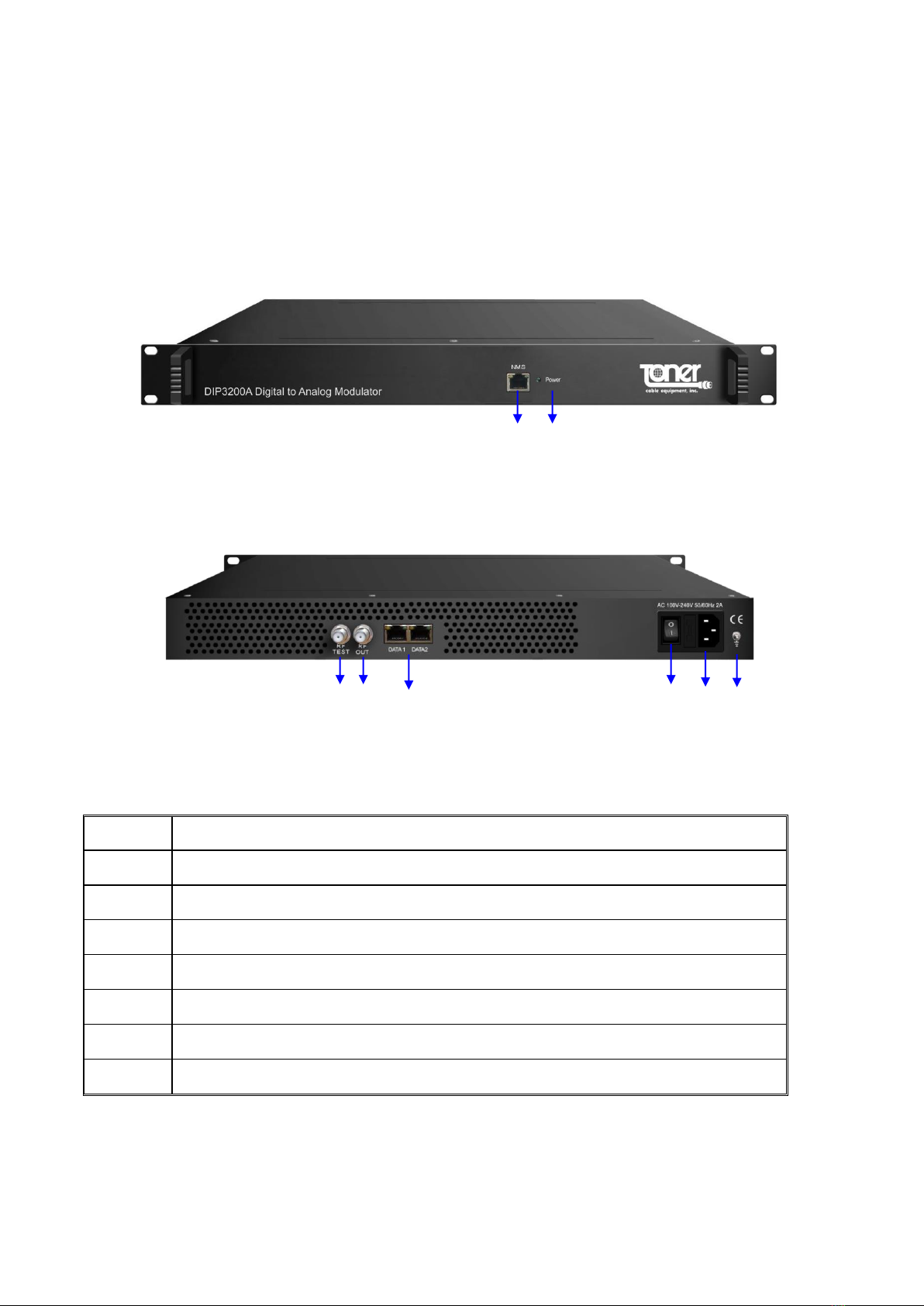
1.3 Appearance and Illustration
Front Panel Illustration
Rear Panel Illustration:
1
NMS: network management port
2
Power Indicator
3
Grounding/ Earthing connection
4
AC Power Connection (IEC Jack)
5
Power switch
6
Content Input RJ-45 Jacks (2)
7
RF output connector, F Female
8
RF test connector, F Female – dB
4
5
6
7
1
3
2
8

4
Chapter 2 Installation Guide
2.1 Grounding
It is recommended that the chassis be grounded using the grounding screw on the rear
2.2 Power cord connection
The power socket is located on the rear panel, and the power switch is next to it.
2.3 Content connection
Use a standard Category 5 or higher Ethernet cable(s) to connect the DIP3200A to your
signal source
2.3 Management and web connection
Use a standard Category 5 or higher Ethernet cable to connect the DIP3200A to a network
or computer

5
Chapter 3 Web NMS Management
Setup and management can only be done using the IP network jack on the front panel
3.1 Login
The factory default IP address is 192.168.0.136
Launch the web browser and input the DIP3200A IP address in the browser’s address bar
and press Enter.
The Login box will appear (Figure-1). Enter the default Username and Password. Both the
default Username and Password are “admin” without the “. Then click on Login” to enter the
setup screen
Figure-1
3.2.1 Login Screen
When correctly logged in the following screen will appear (Figure-2).
Figure-2
6
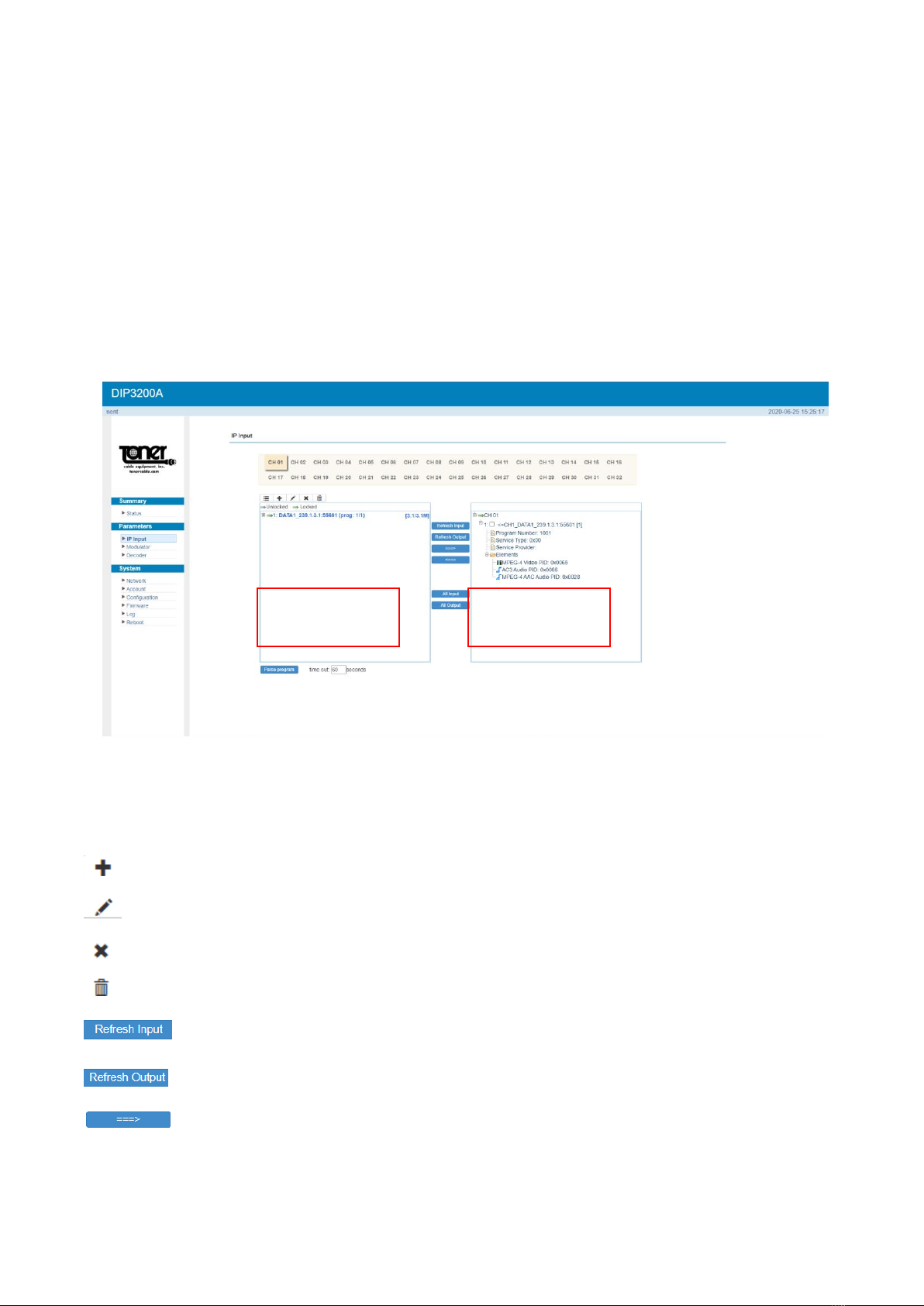
3.2.2 Settings IP Input:
Click “IP Input” on the left side of the screen to set up the input IP’s (Figure-3).
Select at the top of the screen which channel you want the program on. CH01 will be the first
channel in your output which you will select later when you set up modulation.
Here is where you select the Programs from the inputs on the left and select the outputs
selecting the ===> button to add them to the Output area. Here you will see the details of the
channel.
Figure-3
Configure ‘Input Area’ and ‘Output Area’ with buttons in ‘Operation Area’. Instructions are as
below:
: To add input channel which come from Data1 or Data 2 or Data Module (front panel)
: To edit the input channel
: To delete the input channel
: To delete all inputs channel
To refresh the input program information
To refresh the output program information
Select one input program first and click this button to transfer the selected
program to the right box to output.
Input Area
Output Area

7
Similarly, user can cancel the multiplexed programs from the right box.
To select all the input programs
To select all the output programs
To parse programs time limitation of parsing input programs
3.2.3 Settings Output: Modulator:
Select “Modulator”, to set up the analog output channels (Figure-4) NOTE all your channels
must be within a 400 MHz wide bandwidth window. The DIP3200A will not allow you to
select a channel beyond the window so make sure your first channel and last channel are
no more than 394 MHz apart.
Figure-4
Remember to save changes, refer to 3.3.3
The analog output channels are selected based on the picture carrier frequency. Use the
Frequency List (Figure 5) to choose the correct frequency for the channel you want.
Channel 1 will be the first program you selected on the IP Input and Channel 2 will be the
second channel selected and so on.

8
Channel Video Audio Channel Video Audio Channel Video Audio
2 55.25 59.75 42 331.275 335.775 87 601.25 605.75
3 61.25 65.75 43 337.263 341.763 88 607.25 611.75
4 67.25 71.75 44 343.263 347.763 89 613.25 617.75
5 77.25 81.75 45 349.263 353.763 90 619.25 623.75
6 83.25 87.75 46 355.263 359.763 91 625.25 629.75
95 91.25 95.75 47 361.263 365.763 92 631.25 635.75
96 97.25 101.75 48 367.263 371.763 93 637.25 641.75
97 103.25 107.75 49 373.263 377.763 94 643.25 647.75
98 109.275 113.775 50 379.263 383.763 100 649.25 653.75
99 115.275 119.775 51 385.263 389.763 101 655.25 659.75
14 121.263 125.763 52 391.263 395.763 102 661.25 665.75
15 127.263 131.763 53 397.263 401.763 103 667.25 671.75
16 133.263 137.763 54 403.25 407.75 104 673.25 677.75
17 139.25 143.75 55 409.25 413.75 105 679.25 683.75
18 145.25 149.75 56 415.25 419.75 106 685.25 689.75
19 151.25 155.75 57 421.25 425.75 107 691.25 695.75
20 157.25 161.75 58 427.25 431.75 108 697.25 701.75
21 163.25 167.75 59 433.25 437.75 109 703.25 707.75
22 169.25 173.75 60 439.25 443.75 110 709.25 713.75
7 175.25 179.75 61 445.25 449.75 111 715.25 719.75
8 181.25 185.75 62 451.25 455.75 112 721.25 725.75
9 187.25 191.75 63 457.25 461.75 113 727.25 731.75
10 193.25 197.75 64 463.25 467.75 114 733.25 737.75
11 199.25 203.75 65 469.25 473.75 115 739.25 743.75
12 205.25 209.75 66 475.25 479.75 116 745.25 749.75
13 211.25 215.75 67 481.25 485.75 117 751.25 755.75
23 217.25 221.75 68 487.25 491.75 118 757.25 761.75
24 223.25 227.75 69 493.25 497.75 119 763.25 767.75
25 229.263 233.763 70 499.25 503.75 120 769.25 773.75
26 235.263 239.763 71 505.25 509.75 121 775.25 779.75
27 241.263 245.763 72 511.25 515.75 122 781.25 785.75
28 247.263 251.763 73 517.25 521.75 123 787.25 791.75
29 253.263 257.763 74 523.25 527.75 124 793.25 797.75
30 259.263 263.763 75 529.25 533.75 125 799.25 803.75
31 265.263 269.763 76 535.25 539.75 126 805.25 809.75
32 271.263 275.763 77 541.25 545.75 127 811.25 815.75
33 277.263 281.763 78 547.25 551.75 128 817.25 821.75
34 283.263 287.763 79 553.25 557.75 129 823.25 827.75
35 289.263 293.763 80 559.25 563.75 130 829.25 833.75
36 295.263 299.763 81 565.25 569.75 131 835.25 839.75
37 301.263 305.763 82 571.25 575.75 132 841.25 845.75
38 307.263 311.763 83 577.25 581.75 133 847.25 851.75
39 313.263 317.763 84 583.25 587.75 134 853.25 857.75
40 319.263 323.763 85 589.25 593.75 135 859.25 863.75
41 325.263 329.763 86 595.25 599.75
Figure-5
9
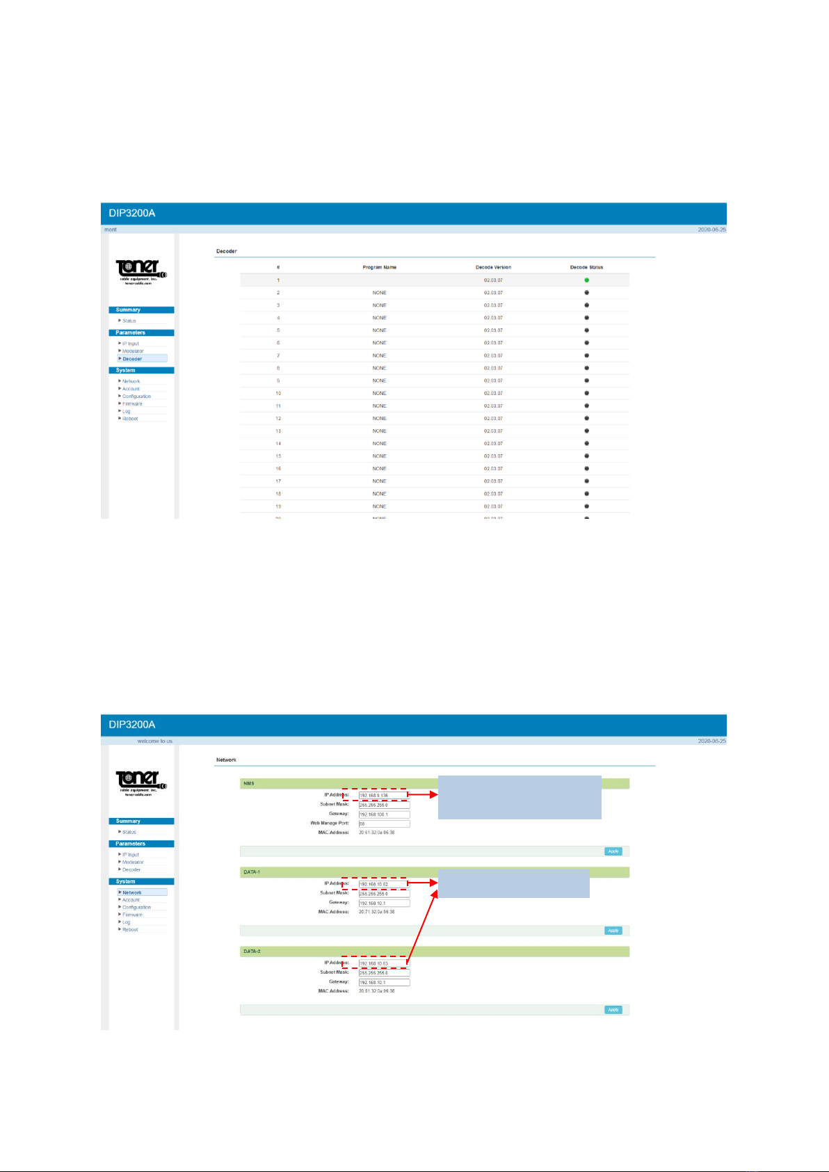
3.2.4 Settings → Decoder:
This function is to monitor status of decoding. It displays the interface as (Figure-6).
Figure-6
3.3 System
3.3.1 Network:
Click ‘Network’, it displays the interface as (Figure-7) where to set network parameters.
Figure-7
Set data port IP
address
To modify IP input
address
10
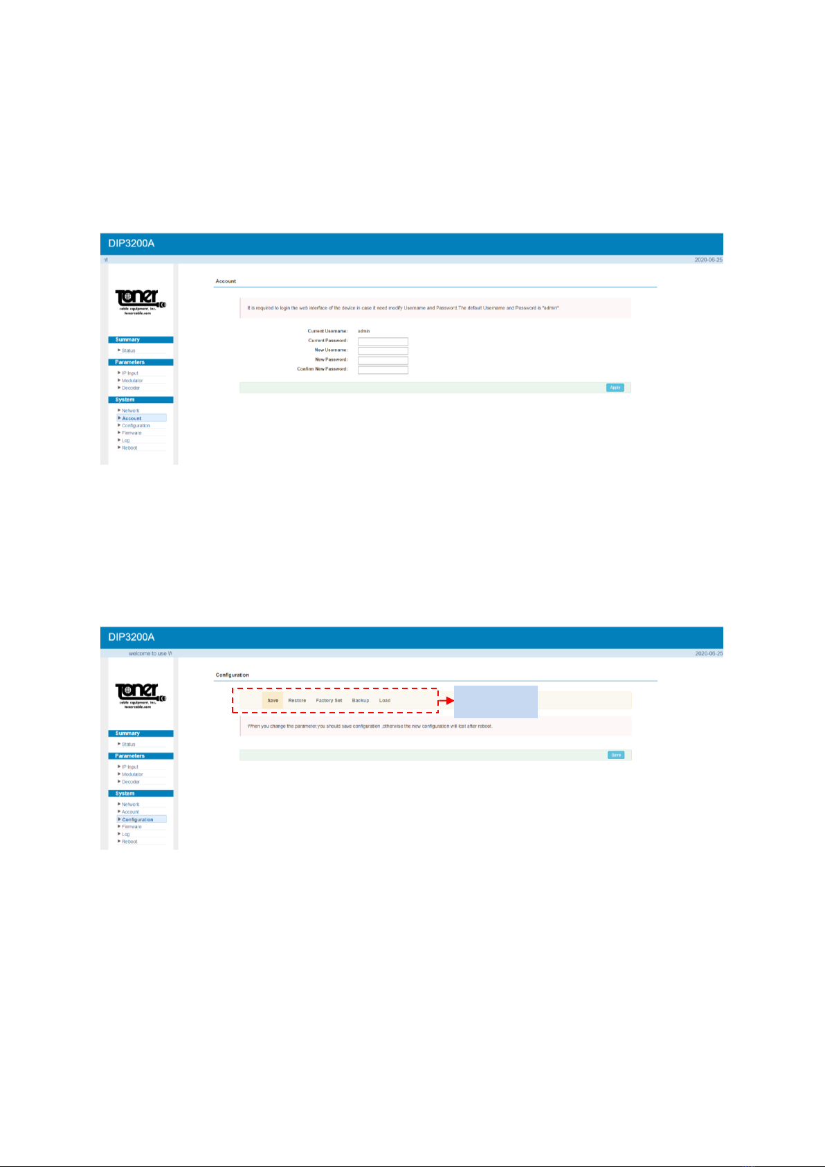
3.3.2 Account:
Click “Account”, it displays the screen as (Figure-8) where you can change login username
and password for the web interface.
Figure-8
3.3.3 Configuration:
Click “Configuration”, it displays the screen as (Figure-9) where to set your configurations
for the DIP3200A.
Figure-9
Remember to save changes, refer to 3.3.3
Select
areas
11
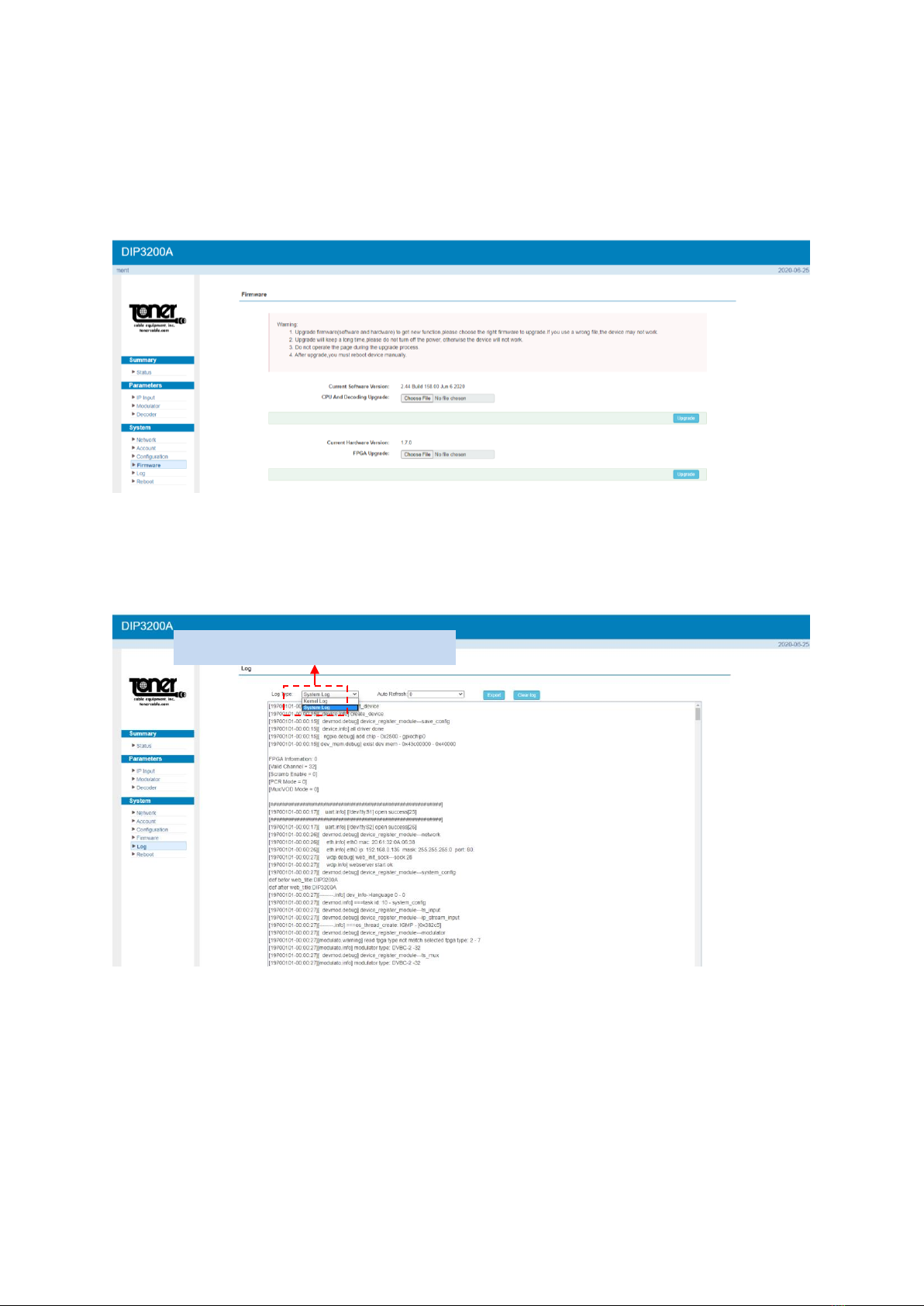
System →Firmware:
Click “Firmware”, it displays the screen as (Figure-10) where to update firmware for the
device.
Figure-10
System →Log:
Click “Log”, it displays the screen as (Figure-11) where to check the “Log”.
Figure-11
To select “Kernel Log” and “System Log”
12
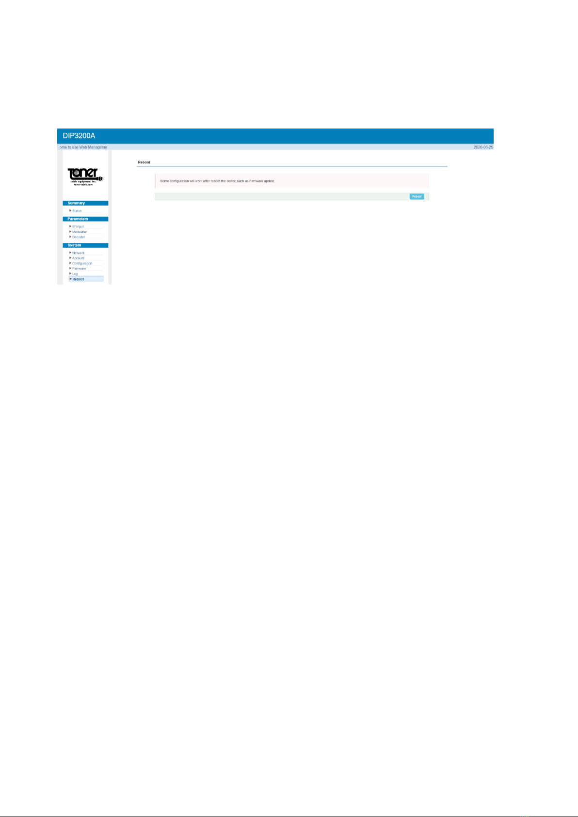
System →Reboot:
Click “Reboot”, it displays the screen as (Figure-12) where to check the “Reboot”.
Figure-12

13
Precautions
Do not install in an environment that exceeds 110 degrees F.
When installing in a rack make sure there is one full empty rack space above and
below the unit.
Install where there is good ventilation, do not install in a dusty environment such as a
laundry.
Make sure the electrical outlet is the correct voltage.
Make sure all connections are tight and installed properly.
Make sure that there are not power issues. If the power switches on and off quicker
than 10 second intervals, this could cause damage to the unit. Unplug the unit and
wait for the power problem to be corrected.
Check to make sure the top ventilation opening is not obstructed in any way.
Table of contents
Other Toner Modulator manuals


Popular Modulator manuals by other brands


Polytron
Polytron HDM 1 SL user manual

PROception
PROception proMOD1 Installation and operation instructions

Comtech EF Data
Comtech EF Data SDM-2020 Installation and operation manual

Security-Center
Security-Center Profiline TV8682 installation guide

Technomate
Technomate TM-RF HD IR user manual

Hinds Instruments
Hinds Instruments PEM-CSC user manual


