TONO THETA-7000E User manual

TONO
COMMUNICATIONS COMPUTER
Θ- 7000E
INSTRUCTION MANUAL
TONO CORPORATION
230 MOTOSOJA-MACHI, MAEBASHI-SHI, 371. JAPAN

TABLE OF CONTENTS
1. Features & Precautions ....................................................... 1
2. Location and Function of controls ......................................... 4
i) Front panel (Keyboard)
ii) Back panel
3. ccessories supplied ........................................................... 7
4. Connection ......................................................................... 7
4-1. Basic System ........................................................ 7
i) Power Supply
ii) TV set
iii) Transceiver
4-2. Expanded System ................................................. 10
i) Oscilloscope
ii) Printer
5. Operation
i) Preliminary Setting ......................................... 11
ii) Procedure to Power Up Equipment .................. 11
iii) Speed and Weight Setting ............................. 12
iv) Tuning ......................................................... 13
v) Transmission ................................................. 16
1. Buffer Memory
2. Correction of Miswritten Characters
3. utomatic Key Repeat
vi) Functions ..................................................... 17
1. Channel Memory
2. SEND Function
3. Split Screen
4. Stop of Transmission
5. "Stand-by" Procedure
6. CW Identification
7. Other Function Keys
8. Indications
vii) Using a Tape Recorder for Storage ................ 22
6. pplication of a Microcomputer as an Intelligent Terminal ...... 23
7. How to Set Cells for the Battery Backed-up Memory .............. 23
Key function and display ......................................................... 24
Special Character SCII 00–1F ................................................ 27
Specifications ......................................................................... 28
Input/ Output Circuit .............................................................. 29

- 1 -
1. FEATURES & PRECAUTIONS
Features:
1. Communications Computer Θ-7000E
Due to the most up-to-date computer technology, one piece of equipment can now handle
both transmitting and receiving in CW, RTTY and SCII.
2. VHF and Composite video output provided:
Both a home TV set and video monitor outputs are provided for display purposes.
3. Printer interface
Centronics para. Compatible interface enables easy connection of a low-cost dot printer for
hard copies.
4. Wide range of transmitting and receiving speeds
10 communication speeds for transmitting (with automatic CW speed adjustment of re-
ceive) and 9 communication speeds for transmitting and receiving in RTTY and SCII. The
multiple speed feature makes the Θ-7000E ideal for mateur, business and commercial use.
5. Built-in demodulator for high performance
Three-step shift (either 170 Hz, 425 Hz, 850 Hz) can be obtained using either High Tone or
Low Tones. Manual adjustment is available by FINE TUNING control.
6. Crystal controlled modulator
transceiver without FSK function can transmit in RTTY mode by utilizing the high stability
crystal-controlled modulator controlled by the computer.
7. Convenient SCII key arrangement
The keyboard layout is the same as a regular typewriter and automatic insertion of LTR/FIG
code makes operation a breeze.
8. Large capacity display memory
The two-page display memory contains 32 characters × 16 lines per page. Page selection
is operated via the keyboard.
9. Split-screen
With a keyboard command, the first page can be divided in two; the upper half for transmit
and the lower half for receive. Sentences can be edited whilst receiving.
10. utomatic Transmit/Receive switch
The transmit/receive switch is controlled by the microprocessor. (Manual operation is also
available.) Built-in remote control key function controls the transmit/receive switch of the
transceiver.
11. nti-noise
new anti-noise circuit prevents garbled messages when there is no signal.
12. Battery backed-up memory
Data in the battery backed-up memory is retained when the external power source is re-
moved. The Θ-7000E has provision for 64 characters × 7 channels in the non-volatile
memory. Data from a memory can be repeated 1–9 times from a keyboard instruction.
Every channel can read out continuously. The channel number in use is displayed in the
buffer.
13. SEND function
The SEND function sends data displayed on the screen, including any channel data after in-
struction from the keyboard. The message can be stopped and restarted.
14. Buffer memory
53-character-buffer-memory is displayed on the 17
th
and 18
th
lines on the screen. The
characters move to the left erasing one by one as soon as they are transmitted. Data in the
channels can be displayed in the buffer.
15. Rub out function
Mistakes can be erased whilst the information is still in the buffer memory. If the mistake
has already been sent a correcting code will be transmitted.
16. Simultaneous access of the memory
Whilst receiving, it is possible to write into the channel memory and the buffer memory
from the keyboard. When sending from the channel memory or the screen it is possible to

- 2 -
write into the buffer memory.
17. Pre-loading function
The buffer memory can momentarily store data and release it on an instruction from the
keyboard.
18. Channel No., Page No., and Case No.
Channel No., Page No., and Case (LTR/FIG) in RTTY are displayed in the 17
th
line of the
screen.
19. CR (Carriage return)/LF (line feed) cancel function
When receiving CR or LF, they are replaced by = (equal) and _ (underline) respectively for
effective use of the screen.
20. Cursor control function
Full cursor control (up/down-left/right) is available from the keyboard.
21. WORD MODE operation
Characters can be transmitted by word groupings.
22. utomatic CR/LF
While sending, CR/LF are automatically inserted once every 72 (64 or 80) characters.
23. utomatic LETTER code insertion
With LETTER switch ON, LETTER code can be transmitted continuously while transmitting
from the keyboard is stopped.
24. ECHO-B CK function
With a keyboard instruction, received data can be read and sent out at the time. cassette
tape can be used as the source data.
25. WORD-WR P- ROUND function
In receive mode word-wrap-around prevents the last word of the line from splitting in two.
This function is released with a keyboard instruction.
26. Transmit/receive in SCII mode in RTTY
On instruction from the keyboard, the same FSK signals as used in RTTY are transmitted
in SCII mode.
27. CW Identification function
Keyboard controlled CW identification is available if required.
28. M RK- ND-BRE K (SP CE- ND-BRE K) system
Either mark or space tone can be used to copy RTTY.
29. Monitor circuit
built-in-monitor circuit with an automatic transmit/receive switch enables checking of the
transmitting and receiving state. In receive mode it is possible to check the output of the
mark filter, the space filter and GC amplifier prior to the filters.
30. CW practice function
The Θ-7000E reads data from the key and displays the characters on the screen.
31. Variable CW weights
For CW transmission, weights (ratio of dot to dash) can be changed within the limits of
1:3–1:6.
32. Cross-pattern checking output terminal
Provision has been made for attachment of an oscilloscope to aid tuning. This supplements
the tuning LED and audio monitor provided in the system.
33. Log-computer output provided
The Θ-7000E has an output terminal for connection to a log-keeping computer.
34. Test message function
"RY" and "QBF" test messages can be repeated with this function.

- 3 -
Precautions:
1. Before operating the set, please read this INSTRUCTION M NU L thoroughly.
2. Before using with a transceiver practice with a TV set.
3. djust SWR between the transceiver and antenna as follows:
OUTPUT SWR
10 W 1.5
10 W – 100 W 1.3
100 W – 500 W 1.1
4. Take care to properly connect in. the connection to the input circuits and output circuits. Input
signal and load should be within the ratings.
5. Voltage of DC power supply should be within the range of DC 11 V – 14 V.
6. Where the Input impedance of the TV set is 300 ohms (not 75 ohms) put a matching trans-
former of 75 ohms : 300 ohms between the Θ-7000E and the TV set.
7. DC power supply for the Θ-7000E should not be connected to other sets.
8. The Θ-7000E should be installed at a well-ventilated dry place not exposed to the direct rays of
the sun with special care for heat radiation.
9. While automatic CR/LF insertion function is working, CR/LF is inserted automatically at space
which is written anywhere but in the last 5 letters of line.
10. Use RTTY modem at 150 Baud less.

- 4 -
2. LOCATION AN FUNCTION OF CONTROLS
i) Front panel (Keyboard)
1. POWER pilot LED: lights when the POWER switch is turned ON.
2. POWER switch
3. F switch: [ GC] output from GC can be monitored
[M RK] or [SP CE] output from respective filters can be monitored.
4. XMIT indicating LED: turns on and of with SHIFT X operated when the REMOTE switch is set
at M NU L; turns on and off corresponding to key operation while at UTO.
5. OUTPUT indicating LED: indicates output level. It lights at the time of "mark" and does not
light at the time of "space". V.V.
6. VOL: controls the volume of a monitor speaker.
7. SP CE indicating LED: Indicates space of input signal.
8. FINE tuning control: provides the fine tuning of shift width in receiving in B UDOT mode and
RTTY of SCII.
9. M RK indicating LED: Indicates mark of input signal.
10. TONE switch: indicates High Tone or Low Tone in RTTY.
11. SENSE switch: changes the polarity of mark/space in input and output.
12. MODE switch: for mode selection.
13. SHIFT switch: sets shift width in RTTY
14. WORD switch: transmits characters in the buffer memory by word groupings by pushing
SPACE (or LF or CR ).

- 5 -
15. OPER TION switch: controls the state of the keying circuit.
16. INPUT switch: [TTL] obtains input from TTL LEVEL IN jack.
[ F] obtains input from others.
17. F INPUT switch: relates to F INPUT jacks on the back panel.
18. NTI-NOISE switch: Helps to prevent garble when there is no signal.
19. SCII MODEM switch: relates to F INPUT KCS and RX/T PE on the back panel.
20. LETTER switch: LETTER code is transmitted when transmitting in RTTY.
21. REMOTE switch: puts the transceiver in transmitting state by pushing any key ( UTO) or
SHIFT X (M NU L).
22. WRITE |CH1 key ┐
23. READ | CH2 key │
24. SEND |CH3 key │
25. CLEAR | CH4 key │ Refer to page 22
26. HOME | CH5 key │
27. |CH6 key │
28. | CH7 key │
29. WEIGHT | SPEED key ┘
30. PAGE | CASE key
31. [ RESET ] key: put the set in the initial state.

- 6 -
ii) Back panel
1. PHONE jack: Connect with an earphone
2. FUSE: 2
3. VIDEO RF jack: Connect with a home TV set.
4. VIDEO COMPOSITE jack: Connect with a video monitor.
5. POWER supply jack: DC 12 V in
6. OSCILLO SP CE jack: Oscilloscope should be connected to this jack for the space output for
cross pattern.
7. OSCILLO M RK jack: Oscilloscope should be connected to this jack for the mark output for
cross pattern.
8. FSK ID jack: Connect 100 kΩ – 200 kΩ resistor for CW identification.
9. FSK KEY jack: Connect with RTTY keying terminal of the transceiver for FSK function in RTTY.
10. CW KEY POSI jack: Connect to the transceiver for CW (refer to page 8)
11. CW KEY NEG jack:
12. REMOTE jack: Connect to PTT terminal of the transceiver for remote control.
13. FSK OUT T PE jack: Connect to MIC terminal of the cassette tape recorder.
14. G IN control: Controls the FSK output level.
15. FSK OUT TX jack: Connect to MIC terminal of the transceiver.
16. F INPUT T PE jack: Connect to E RPHONE terminal of the tape recorder.
17. F INPUT RX jack: Connect to EXT SP terminal or line output of the transceiver.
18. F INPUT KCS jack: Connect to E RPHONE terminal of the tape recorder.
19. TTL LEVEL OUT jack: For output in TTL level without modulation.
20. TTL LEVEL IN jack: For non-modulated signals in CW, B UDOT or SCII and when using with a
hand key.
21. PRINTER C BLE OUTLET

- 7 -
3. ACCESSORIES SUPPLIE
Instruction manual 1
Pin plug 16
Headphone plug 1
Power source cord 1
Coaxial cable 4 m
Connector for printer 1
4. CONNECTION
4-1 Basic System
i) Power supply
Before connecting a power lead to your DC power supply, the setting of the voltage must
be within the range of DC 11 V – 14 V.
fter confirming that the DC source switch and POWER switch of the Θ-7000E indicates
OFF, connect a plus (+) of POWER supply jack of the Θ-7000E with the plus (+) terminal of
DC source; minus (–) with minus (–) terminal.
ii) TV set
1. Solder an ancillary coaxial cable and a pin plug as shown in Fig. 3. fter having soldered,
connect the pin plug to the RF pin jack of the Θ-7000E and the other end of the coaxial ca-
ble to an antenna terminal of a home TV set. Tune TV set to CH3 or CH4,
Fig. 3
or 2. Connect the pin plug to COMPOSITE pin jack for a display monitor.
We recommend you TONO display monitor model: CRT-12,, which is specially designed for
mateur radio communications and has very stable display without being interfered by a
electric wave.
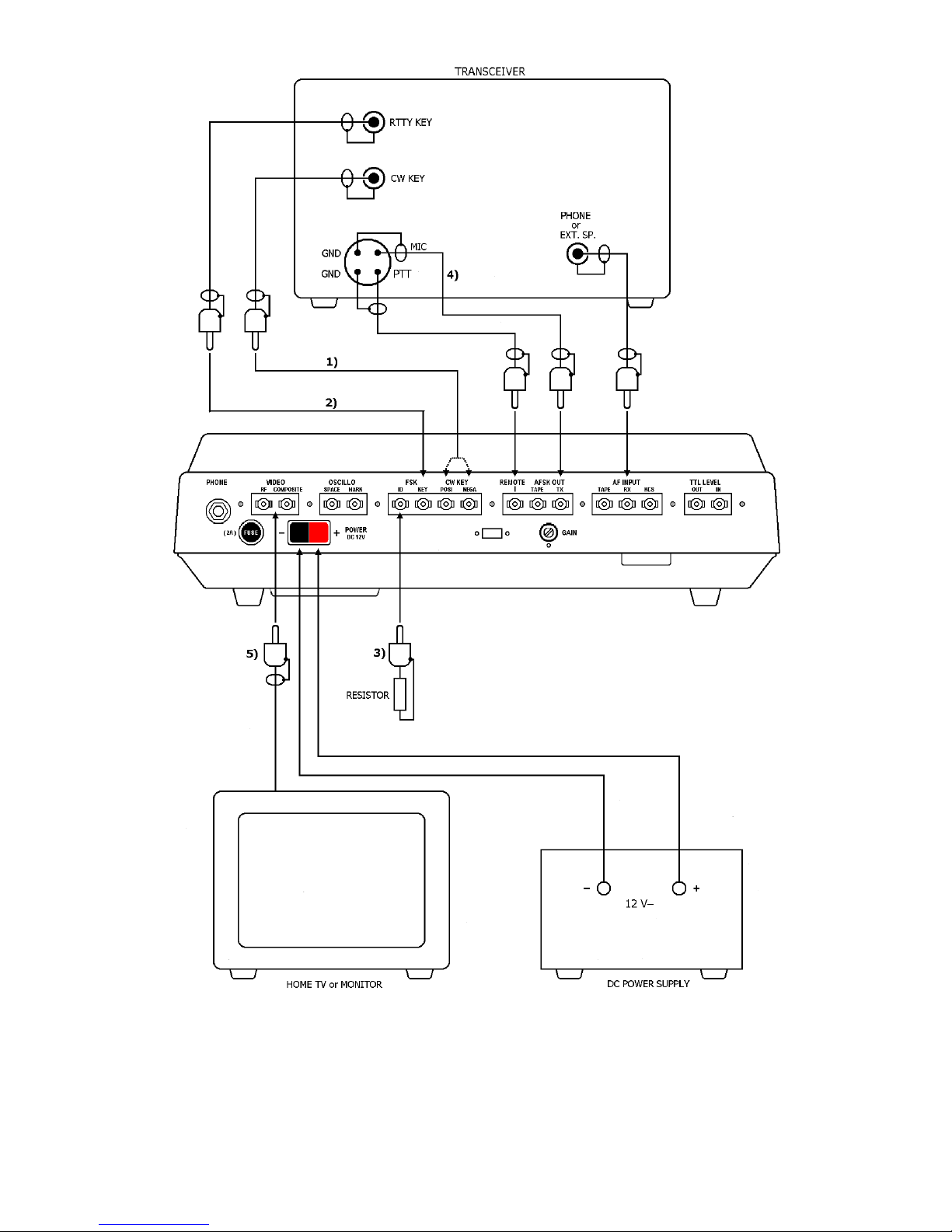
iii) Transceiver
Make sure SWR is as follows; to enable correct operation.
OUTPUT SWR
10 W 1.5
10 W – 100 W 1.3
100 W – 500 W 1.1
Table 1
- 8 -
Fig. 4
NOTE: 1) Check the polarity against the ground by the tester and connect with the respective
jack.
2) No need to connect when using with FSK function of Θ-7000E.
3) Only for CW identification with FSK function of the transceiver.
4) No need to connect when using with FSK function of the transceiver.
5) For Home TV set "RF"; for Monitor set "COMPOSITE".
- 9 -
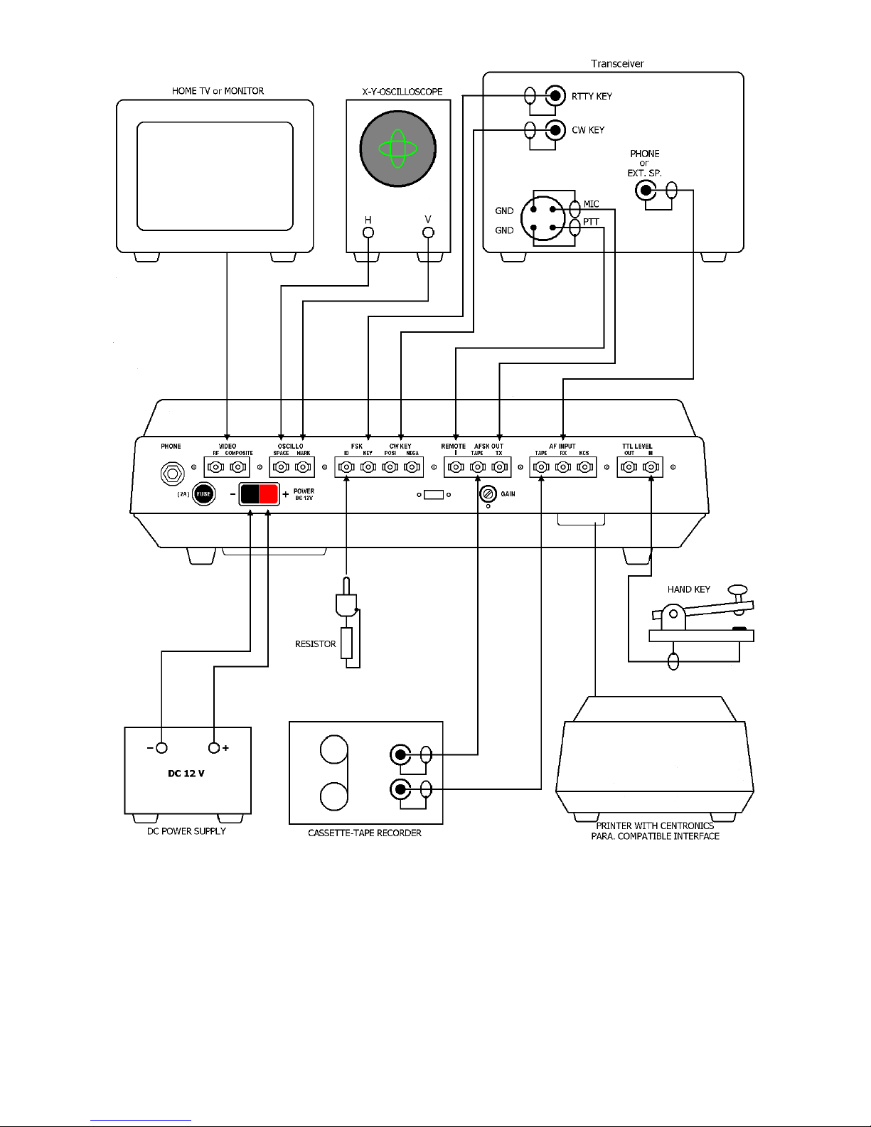
Fig. 5
- 10 -
4-2 Expanded System
Refer to page 9 for detail.
i) Oscilloscope
s output impedance for oscilloscope is 200 kΩ, use an oscilloscope whose input im-
pedance is over 1 MΩ. s output for oscilloscope is about 1.2 V
PP
, large cross pat-
tern cannot be obtained without an amplifier in horizontal-amplifier of the oscillo-
scope.
ii) Printer
printer which has Centronics compatible interface can be connected directly with
the Θ-7000E.
We recommend the TONO printer model HC-800, which is easy to connect because
of its supplied cable with connector for the Θ-7000E.
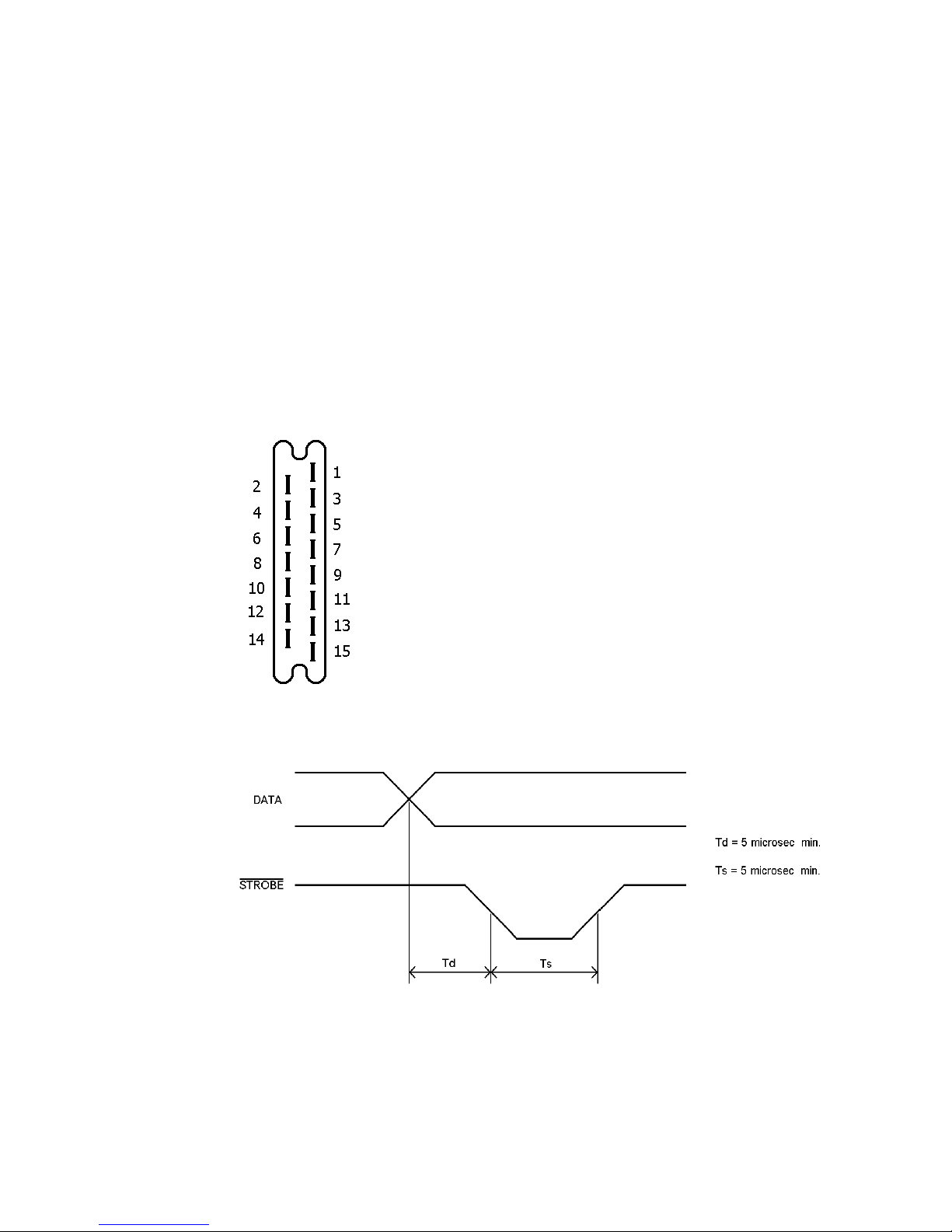
Connector CN8 on the CPU board is a connector for a printer. The function of each
pin is as follows. The fan-out of each pin is 5 standard TTL loads. void overload!
Connect any of them to your printer is required.
15 V (leave this non-connected
_____
2 RE DY (input)
____
3 BUSY (output (leave this non-connected)
______
4 STROBE (output)
5 – 12 Parallel data in SCII
5
th
pin = LSB
12
th
pin = MSB
13 SERI L OUT (leave this non connected)
14 SERI L IN (leave this non-connected)
15 GROUND
Fig. 6
_____
When RE DY is "L" level, timing of data for printer is as follows:
Fig. 7
_____
When RE DY is "H" level, the port for printer holds the previous data. The printer should print and
make CR/LF with LF instruction or CR instruction.

- 11 -
5. OPERATION
i) Preliminary Setting
Theta-7000E
Front
Panel
POWER
sw
VOL
tuning control
MODE sw
OPER TION
sw
SENSE sw
REMOTE sw
SCII MODEM
sw
F INPUT
sw
LETTER
sw
NTI-NOISE
sw
INPUT
sw
WORD
sw
F
sw
FINE
tuning control
TONE
sw
SHIFT
sw
OFF
medium
---
NORM
NORM
---
KSC
RX
---
---
F
---
GC
medium
---
(any place)
when in B UDOT
mode select the
proper shift
Back
Panel FSK G IN
control
around medium
--- : as required
DC power supply
POWER
sw
OFF
TV set
POWER
sw
VHF channel
(Home TV)
OFF
CH 4 ( ustralia &
Continental)
CH 3 (US )
Transceiver
MODE sw
according to the MODE sw
setting of the Θ-7000E.
w/o FSK function
LSB setting is required for
RTTY.
POWER sw OFF
F volume
Set it so as to make the input
voltage into the Θ-7000E
ranging from 50 mV to 1 V
(ordinary listening volume)
Table 2
ii) Procedure to power up equipment
Put the power switch ON of: 1. TV set
2. DC power supply
3. The Θ-7000E
4. Transceiver
When you get POWER pilot LED light and indications on the TV screen as shown in Fig. 8,
your Θ-7000E is all ready to go!
If using RF input, it may be necessary to find correct channel – either 3 or 4 – and adjust
fine tuning.
Fig. 8
- 12 -
iii) Speed and Weight Setting
[1] CW (MORSE)
RECEIVING SPEED
Receiving speed is automatically determined. Dots which are less than 20 msec may be regarded
as noise. However, when slow CW is received right after rather fast CW, 2 – 4 characters are re-
quired before synchronization is achieved.
For the faster sync, in high speed
WEIGHT | SPEED →H
(Push) (and then push)
For the faster sync, in low speed
WEIGHT | SPEED →L
When the receiving speed of signals suddenly diminishes to less than half, it will sometimes hap-
pen that 8 – 12 characters are read as E or T by mistake. However, correct reading will be ob-
tained with the continuation of the CW signals at the new rate.
TR NSMITTING SPEED
Transmitting speed is automatically set at the speed of about 50 characters per minute in the initial
state.*
(* Pushing POWER switch ON or [ RESET ] key makes the initial state.)
For the speed change
WEIGHT | SPEED →Ø ~ ) | 9
There are ten speeds to be selected as shown in Table 3.
Ø about 25 char./min. % | 5 about 87 char./min.
! | 1 about 32 char./min. | 6 about 113 char./min.
" | 2 about 41 char./min. ' | 7 about 147 char./min.
# | 3 about 52 char./min. ( | 8 about 188 char./min.
$ | 4 about 68 char./min. ) | 9 about 250 char./min.
Table 3
WEIGHT SETTING
Weight (ratio of dot to dash) is automatically set at 1:3 in the initial state.
For the weight change
SHIFT | WEIGHT | SPEED →Ø ~ ) | 9
There are ten steps within the limits of 1:3 – 1:6.

- 13 -
[2] RTTY (B UDOT)
Transmitting/receiving speed is automatically set at 45.45 baud in the initial state.
For the speed change
WEIGHT | SPEED →Ø ~ ) | 9
Selection will be obtained as shown in Table 4.
Ø 45.45 Baud % | 5 110 Baud
! | 1 50 Baud | 6 150 Baud
" | 2 56.88 Baud ' | 7 200 Baud
# | 3 74.2 Baud ( | 8 300 Baud
$ | 4 100 Baud ) | 9 300 Baud
Table 4
NOTE: 45.45 Baud is popular among mateurs and 50 Baud is usually used in business
communications.
For the adjustment
SHIFT Z speed up (the length of a bit becomes about 0.16 msec shorter per
time)
SHIFT S speed down (about 0.16 msec shorter per time)
[3] SCII
Transmitting/receiving speed is automatically set at 110 baud in the initial state.
For speed change and selection, refer to RTTY.
[4] Mode change under running condition
Speed setting is necessary. Be sure to push [ RESET ] key when B UDOT or SCII mode is
changed into CW mode; otherwise the tone frequency of FSK is set at "Mark" frequency of
B UDOT/ SCII mode.
iv) Tuning
TR NSMITTING
[1] CW (MORSE)
Tune the transceiver when keying output is ON and with OPER TION switch at TEST and
SENSE switch at NORM. fter tuning, set OPER TION switch to NORM (refer to page 21).
[2] RTTY
In RTTY when using FSK complete tuning by adjustment of microphone-gain of the trans-
ceiver, avoiding excess modulation and over drive.

- 14 -
RECEIVING
[1] CW (MORSE)
Using LED indicator
1. Receive CW with the transceiver.
2. SP CE indicating LED lights when the CW signals from the transceiver pass through the
band-pass-filter of which the central frequency is 830 Hz.
3. Tune VFO or RIT of the transceiver so as to make this SP CE indicating LED have maxi-
mum brightness.
Using audio level
1. Set F switch to SP CE.
2. Output of the band-pass-filter can be heard.
3. djust the transceiver to have the maximum sound level.
If the SP CE indicating LED begins to flicker corresponding to signals, the Θ-7000E reads
properly and will display on the TV screen. Special characters are displayed as shown in Ta-
ble 5.
CW special character Display
__
BT =
__
KN (
__
HH >
__
R +
__
S ^
__
V ;
__
@
Table 5
[2] RTTY (B UDOT)
1. Tune in RTTY signals with the transceiver.
2. Increase the F output frequency gradually from the lower value with the VFO or RIT
until M RK indicating LED lights.
3. Continue increasing the frequency.
4. Stop increasing the frequency when the M RK indicating LED lights again and comes to
light at maximum brightness.

- 15 -
5. SP CE indicating LED lights at this moment if the shift width of RTTY signal agrees with
the setting of the Θ-7000E.
│
│ YES
│
│
│
│
│
│ ┌──────────────────
│ │ YES
▼
▼
│
NO │
▼
5. If SP CE indicating LED does not
light, turn the FINE tuning control
to catch the position where it
lights.
─
NO │
▼
6. Turn the FINE tuning control and
stop it at the maximum brightness
of SP CE indicating LED.
6. Change SHIFT width so as to
make SP CE indicating LED light
and turn the FINE tuning control
to make the lighting the maxi-
mum brightness.
When tuning is completed, right characters will be displayed on the screen.
│
NO │
▼
Change the speed setting (See page 13)
│
NO │
▼
Turn *SENSE switch to REV.
│
NO │
│
▼
Input signals are judged not to be RTTY.
For amateur communications, 170 Hz shift is most commonly used; for business communi-
cations, 850 Hz and 425 Hz shift is usually used. In addition, monitoring of the output of
M RK filter and that of SP CE filter are obtainable by tuning F switch to M RK and SP CE
respectively. The output of M RK filter and SP CE filter can function in lieu of M RK indicat-
ing LED and SP CE indicating LED.
SHIFT SWITCH HIGH TONE LOW TONE
M RK SP CE M RK SP CE
170 Hz 2125 Hz 2295 Hz 1275 Hz 1445 Hz
425 Hz 2125 Hz 2550 Hz 1275 Hz 1700 Hz
850 Hz 2125 Hz 2975 Hz 1275 Hz 2125 Hz
Table 6
Tuning by cross pattern
In the case of tuning with a cross pattern made on the oscilloscope, adjust VFO and RIT of
a transceiver and FINE tuning control of the Θ-7000E to make amplitude both in V-direction
and in H-direction the maximum.
- 16 -
[3] SCII
When using KCS
Tuning by watching the LEDs or by listening the transmitting sound from the speaker is not
available in this mode.
Receive signals of 2400 Hz for mark and 1200 Hz for space in accordance with KCS (Kansas
City Standard) from a tape recorder or a microcomputer.
When using RTTY ( SCII)
Tuning is the same as in B UDOT mode.
[4] NOISE
NTI-NOISE circuit
When there are too many errors caused by noise when there is no signal, set the NTI-
NOISE switch ON. This circuit may make mistakes with high speed CW (Morse) of which a
dot is shorter than 20 msec.
UNSHIFT-ON-SP CE function (only in B UDOT)
When error in C SE (LTR or FIG) is often made with a lot of noise, push SHIFT Y UN-
SHIFT-ON-SP CE function works and leads the LTR case when space is received.
# is replaced by * on the 17
th
line. To release this function push these keys again.
v) Transmission
Procedure CW (MORSE) B UDOT (RTTY) SCII
1. Setting
The transceiver can be made to transmit by any of the three ways below:
a) utomatic ┌ with REMOTE terminal of the Θ-7000E when connected to PTT
b) Manual └ terminal of the transceiver.
c) Manual change by the switch on the transceiver
or
Semi-break-in state with
VOX turned ON
or
tape recorder in recording
state or microcomputer in
receiving state
2. Transmission Operate the keyboard, when characters corresponding to the respective keys as
in Table 12 are displayed on the screen.
3. OUTPUT in-
dicating LED
lights at
mark space space
4. The trans-
mitting sound heard heard heard
5. Setting The transceiver can be returned to the receiving state by any of the three ways
below:
a) utomatic ┌ with REMOTE terminal of the Θ-7000E when connected to PTT
b) Manual └ terminal of the transceiver.
c) Manual change by the switch on the transceiver

- 17 -
1. BUFFER MEMORY
Characters written in buffer memory are transmitted in order of writing. If the typing speed ex-
ceeds the transmitting speed, characters are stored in the buffer memory up to 53 characters.
With 53 characters being stored, the cursor disappears, gives a sound signal and inputs from the
key are rejected.
For loading of characters in the buffer memory SHIFT V . V will be displayed on the screen. To
release the loaded information, push these keys again.
2. CORRECTION OF MISWRITTEN CH R CTERS
By pushing the HH key, mistakes can be erased, whilst the information is still in the buffer memo-
ry, and correcting code will be transmitted if the mistake has already been set.
If the HH key is pushed when the buffer memory is empty, characters shown in Table 8 are trans-
mitted:
CW
__
HH
B UDOT /
SCII {BS}
Table 8
3. UTOM TIC KEY REPE T
The same signal is repeated when you hold the key pressed. This applies to any key if it is held de-
pressed.
vi) Functions
1. CH NNEL MEMORY
Data in this memory Is retained even when the external power source is removed. The Θ-7000E
has provision for 64 characters × 7 channels in the nonvolatile memory. nd Channel 7 can be div-
ided in 4 parts as shown in Fig. 9.
0 16 32 48 63
Fig. 9
No. 1 reads from the first character to the last you have written in Channel 7; No. 2 from the 16
th
character, No. 3 from the 32
nd
character, No. 4 from the 48
th
character.
[Writing]
1. WRITE | CH1 ~ | CH7
2. SHIFT | WRITE | CH1
Select a channel by pushing the desired CH1 – 7 key. Selected
channel number is shown at the 17
th
line on the screen.
1. NOTE: When you write in CH7, select desired part from
!| 1 to $ | 4 after operating these keys.
3. Type on the keys to write in desired data. audio signal is heard after 64 characters are writ-
ten in. Characters from the keyboard are thereafter to be written on the 64
th
character. The
64
th
character is not displayed on the screen, although it is written in the memory.

- 18 -
4. HH for correction of mistake
5. SHIFT | READ | CH2 By pushing these keys Channel number at the 17
th
line should indicate
Ø.
Example: "CQ DX CQ DX DE DC7XJ K" in CH1
1. WRITE | CH1
2. SHIFT | WRITE | CH1
3. C Q space D X space C Q space D X space D E space D C
' | 7 X J space K
4. SHIFT | READ | CH2
[OUTPUT]
1. WRITE | CH1 ~ | CH7 Select a channel by pushing. Selected channel number is dis-
played on the 17
th
line on the screen. (To cancel the selected
channel push any key except for !| 1 ~ )| 9 )
2. !| 1 ~ )| 9 Designate the number of times you want to send. nd chan-
nels will be displayed in the buffer memory.
Example: CH1 × 3, CH6 × 5, CH3 × 1, CH7 (4)
WRITE | CH1 # | 3 | CH6 % | 5 | CH7 $ | 4
NOTE: Channel 7 can NOT be repeated. fter designating channels and the number of
times the cursors will be displayed in the buffer memory.
3. Writing in the buffer memory is possible also during output from the channel memory.
2. SEND FUNCTION
SHIFT | SEND | CH3 Characters from the Characters from the head of the screen up to one before
the cursor are transmitted. It can send whatever you can write on the screen. In other words, spe-
cial characters such as DEL, ESC, CR or LF cannot be transmitted.
SHIFT BT However in B UDOT mode, CR is transmitted replaced by = (equal) displayed on the
screen and LF by _ (underline). This function also works in receiving in B UDOT mode, received
sentences can be immediately repeated to transmit by SEND function While this function is work-
ing, = will be displayed on the screen. (See Table 11). To release this function, push these keys
again.
s soon as transmission of the sentences on the screen finishes, transmission from the buffer
memory begins. In the case you want to insert characters from the keyboard while sending by
SEND function, write " " in the place you want to stop beforehand.
While stopping at "\", characters from the keyboard are not displayed, although they are transmit-
ted.
To restart it push SHIFT | space or SHIFT | SEND | CH3 .
Table of contents
Other TONO Conference System manuals


