TONO Theta 7000 User manual

TONO
COMMUNICATIONS COMPUTER
Θ- 7000
INSTRUCTION MANUAL
TONO CORPORATION
230 MOTOSOJA-MACHI, MAEBASHI-SHI, 371. JAPAN
TEL 0272-52-6284

**************************** CONTENTS ***************************
Page
1. Features ...................................................................................................... 1
2. How to use ................................................................................................. 5
3. Designation and Explanation of Parts ............................................................ 7
4. How to operate ........................................................................................... 10
4.1 Initiali ation ................................................................................................ 10
4.2 Preliminary setting ....................................................................................... 11
4.3 Procedure for power ON ............................................................................... 11
4.4 Tuning of a wireless set for transmission ........................................................ 12
4.5 Speed setting for transmitting and receiving .................................................. 12
4.6 Weight setting in CW mode ..........................................................................
4.7 Tuning for receiving .....................................................................................
4.8 Recording of signals during receiving ............................................................ 14
4.9 Transmission ............................................................................................... 15
4.10 How to use battery backed-up memory ......................................................... 19
4.11 How to use SEND function ........................................................................... 19
4.12 Stop of transmission .................................................................................... 20
4.13 "Stand-By" procedure .................................................................................. 20
4.14 How to use function key ............................................................................... 20
4.15 How to use a tape recorder .......................................................................... 21
4.16 CW practice ................................................................................................ 21
4.17 Application of a microcomputer as an intelligent terminal ................................ 22
4.18 Operation example ...................................................................................... 22
RATINGS ............................................................................................................... 23
INPUT/OUTPUT CIRCUIT ........................................................................................ 24

- 1 -
1. FEATURES
(1) COMMUNICATION COMPUTER
The Θ-7000 is made with the newest technique of computer; transmits and receives the CW
(Morse Code), RTTY (Baudot code) and ASCII (American Standard Code for Information Interchange)
and projects them to a home TV set. It may be used as an intelligent terminal for a microcomputer as
well as for a wireless set.
(2) WIDE RANGE OF TRANSMITTING AND RECEIVING
Its transmitting-receiving speeds are 10 steps for transmitting the CW, automatic-following for re-
ceiving the CW, 4 steps for transmitting-receiving the RTTY and 2 steps for transmitting-Receiving the
ASCII. It may be effectively used not only for the radio amateur communications but also for the
business communications.
(3) HIGH PERFORMANCE DEMODULATOR
It has an active filter type demodulator of high stability and reliability in it, which results in a very
high communication performance. For the RTTY, three steps (shift with 170 H , 425 H and 850 H )
and 'FINE TUNING' are available, so the demodulator may be very easily operated.
(4) CRYSTAL-CONTROLLED MODULATOR
It has a high precision, high stability crystal-controlled modulator which is controlled by the com-
puter attached to it and the RTTY may be transmitted and received even with a machine without FSK
function.
(5) EASILY OPERATEABLE KEYBOARD ARRANGEMENT
It has a keyboard arrangement about the same as the ordinary typewriter; even for RTTY it is not
necessary to change LTR and FIG manually and the code of LTR and FIG may be added automatically.
(6) LARGE CAPACITY DISPLAY MEMORY
It has the capacity for two pages of 32 characters × 16 lines and the pages may be changed
easily by operating the key switch, so such a use that one page is for receiving and the other page is
for transmitting may be available. When the screen is filled up, the lines go up automatically with the
scrolling function.
(7) AUTOMATIC CHANGE FROM/TO TRANSMITTING TO/FROM RECEIVING
Change of transmitting and receiving is controlled automatically by the computer.
(8) A BATTERY BACKED-UP MEMORY
It has a battery backed-up memory for 32 characters × 7 channels; the sentences do not volatil-
i e when the power source is cut off. The computer will let the machine work automatically at any
time with your key switch operation if you put your call sign or sentences which you often use it.
(9) OUTPUT REPEATING
The sentence memori ed in the battery backed-up memory may be put out repeatedly with the
key switch operation. It may be used very conveniently at calling.

- 2 -
(10) 'SEND-OUT' FUNCTION
The sentence on the screen sent from the keyboard or received from the outside may be sent out
with the key operation of one time from the first character to the character before the cursor. A sen-
tence of up to 511 characters may be sent out at one time.
(11) USE OF A CASSETTE TAPE-RECORDER AS A SUPPLEMENTARY MEMORY
The sentence may be put in the cassette tape-recorder or the sentence may be led in and dis-
played on the screen from the cassette tape-recorder. This function may be very effectively utili ed
being connected with the 'SEND-OUT' function, so paper tapes are no more necessary for the RTTY.
(12) BUFFER MEMORY FOR DISPLAYING ON THE TV
The information in the buffer memory which has the capacity of 23 characters may be put on the
lowest line (17
th
line) on the screen and they move to the left every time one of them is sent out, so
the going -out sentence may be well observed.
(13) 'RUB-OUT' FUNCTION
When a wrong character is sent to the buffer memory from the keyboard, the character may be
canceled before it is sent out of the buffer memory and a correcting code may be put out after it is
sent out.
(14) SIMULTANEOUS ACCESS
During receiving the communication, the sentence may be put in the buffer memory or the bat-
tery backed-up memory. Efficient QSO may be made because the sentence may put in the buffer
memory even when the battery backed-up memory is transmitting or the displaying memory is trans-
mitting with the 'SEND-OUT' function.
(15) PRELOADING FUNCTION
Buffer memory may memori e the sentence sent from the keyboard and by using this function at
the time of receiving, transmitting may be made just after receiving and beautiful continuous may be
sent out.
(16) ONLY THE RECEIVED SENTENCES MAY BE DISPLAYED IF NECESSARY
When you don't need the display of the sent out sentence, only the received sentence may be dis-
played though both of them are available.
(17) DISPLAYING CHANNEL NO., PAGE NO. AND THE CASE
The channel number of the battery backed-up memory, the page number of the screen, the case
(LTR or FIG) in the RTTY may be displayed on the lowest (17
th
) line.
(18) FUNCTION OF CANCELING CR AND LF
When CR (carriage return) or LF (line feed) is received or at writing with the keyboard, CR and LF
are replaced with = (equal) and _ (underline) on the screen respectively and the screen may be used
effectively.
(19) FUNCTION OF CONTROLLING CURSOR MOVEMENT
Cursor movement may controlled by the keyboard. In the case of the ASCII mode, the cursor
movement may be controlled by the external signals and it is effective when the machine is con-

- 3 -
nected to a microcomputer.
(20) SINGLE-SIDED RTTY MAY BE RECEIVED
So-called single-sided RTTY of intermission of either marks or spaces may be clearly received.
(21) 'UNSHIFT ON SPACE' FUNCTION
When you receive a space (space of Baudot code) in the case of the RTTY, the CASE changes to
LTR regardless of the case so far. It may be effective to be used for receiving signals very close to the
noise level.
(22) A MONITOR CIRCUIT
A monitor circuit which automatically changes transmitting and receiving to each other is at-
tached; the situation of transmitting and receiving may be found through the speaker. At the time of
receiving, the output from the mark filter, the output from the space filter and the output from the
AGC amplifier in the front stage of the filter may be monitored.
(23) CW PRACTICE FUNCTION
If you connect the key to this machine and operate the key, the machine will read it and display it
on the screen. In this case, the CW key operation's output circuit works according to the operation of
the key.
At the time of receiving CW, always different sentences may be received by using the output re-
peating function (9) and the 'SEND-OUT' function (10), which makes your practice effective and inter-
esting.
(24) CW WEIGHT IS CHANGEABLE
At transmitting the CW, the length of the dash may be changed in the range of 1:3 ~ 1:6.
(25) OUTPUT TERMINALS FOR OBSERVING THE CROSS PATTERN
The demodulator of this machine may be easily tuned with the tuning indicating LED or the moni-
tor circuit. Output terminals for observing the cross pattern with an oscilloscope are attached.
(26) OUTPUT PORTS FOR A PRINTER
8 bit parallel I/O port is attached for connecting to a printer. In this case, the output is ASCII and
a strobe pulse comes out every time of putting out a character.
(27) DC TWO WAY POWER SOURCE SYSTEM
Both power supplies +12 VDC and +5 VDC may be used.
(28) FUNCTIONAL DESIGN
The keys, switches and others are arranged functionally to be used easily and everything as well
as the case is designed functional and elegant.
(29) CARETAKING COMMUNICATION IS AVAILABLE
Messages may be received while you are out by attaching the option part Θ-22 and making a net-
work with your group members and in this case, no messages may be received from outside the net-
work. Also the RTTY's function may be expanded by the Θ-22.
- 4 -
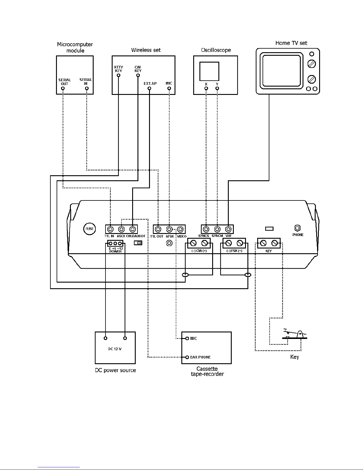
Figure 1: Connection

- 5 -
2. HOW TO USE
2.1 Accessories for the Θ-7000
Instruction manual 1
Pin plug 9
Earphone plug 1
Power source cord 1
Coaxial cable 4 m
2.2 I stallatio
The Θ-7000 should be installed at a well-ventilated dry place not exposed to the direct rays of the
sun with special care for heat radiation.
2.3 Co ectio
(1) Power supply
An ancillary source power supply cord is connected for 12 VDC. In the case of using 5 VDC,
change the connection within source cord connector as shown in Fig. 2.
Figure 2
Before connecting a source cord to your DC power supply, the setting of source voltage is neces-
sary as follows:
In the case of 12 VDC 11 V ~ 13,8 V
In the case of 5 VDC 4.75 V ~ 5.25 V
Source voltage should be stabili ed without ripple in the case of 5 VDC. After confirming a DC
source switch and a power switch of the computer indicate OFF, connect the red source cord of the
computer to a plus (+) terminal of DC source, a black source cord to a minus (–) terminal.
(2) TV set
Solder an ancillary coaxial cable and a pin plug as shown in Fig. 3. After having soldered, connect
the pin plug to a VHF pin jack of the Θ-7000 and the other end of the coaxial cable to an antenna ter-
minal of a home TV set.
Figure 3

- 6 -
(3) Wireless set
Before connecting, adjust SWR as follows:
In the case of output less then 10 W: less than 1.5
In the case of output from 10 W to 100 W: less than 1.3
In the case of output from 100 W to 500 W: less than 1.1
(i) Speaker
Solder the ancillary coaxial cable and a pin plug as shown in Fig. 3. After soldering,
connect the pin plug to the CW/BAUDOT pin jack of the Θ-7000 and the other end to an external
speaker terminal or an earphone terminal of a wireless set.
(ii) In CW mode
Connect the cable to a key jack for CW of a wireless set, check the polarity by a tester
and connect its plus (+) to the plus (+) of a screw terminal for CW of the computer; its minus (–) to
the minus (–) of the computer. Take care not to exceed the rated capacity of keying circuit of 1.5 A,
150 V.
(iii) In RTTY mode
° In the case of a wireless set with FSK function:
Connect the cable to a KEY jack for RTTY of the wireless set, check the polarity by a
tester and connect its plus (+) to the plus (+) screw terminal for FSK of the computer, its minus (–)
to the minus (–) terminal. Special care should be exercised not to exceed the rating: 1.5 A for the
maximum keying circuit current and 150 V for the maximum voltage.
° In the case of a wireless set without FSK function:
Solder the ancillary coaxial cable and a pin plug as shown in Fig. 3. After soldering,
connect the pin plug to a pin jack for AFSK of the Θ-7000 and the other end to a microphone terminal
of the wireless set. The shielding braids of the cable should be connected to GND side of the micro-
phone terminal.
(4) Key
For manipulation practice in CW mode, connect keys to a screw terminal for KEY of the com-
puter.
(5) Oscilloscope
Cross pattern can be observed with oscilloscope by the following procedures: solder the co-
axial cable or shield cable with two pin plugs respectively as shown in Fig. 3; after soldering, connect
the pin plugs to pin jacks, SYNCM and SYNCS; connect the cable in SYNCM to the V-axis input to the
oscilloscope and the cable in SYNCS to the H-axis input.

- 7 -
3. Desig atio a d Expla atio of parts
3.1 Keyboard
Figure 4
(1) POWER switch: Power Switch
(2) POWER pilot LED: Lights when the power switch is turned on.
(3) VOL: Controls the volume of a monitor speaker.
(4) RESET switch: Initiali es the computer
(5) LTRS/FIGS indicating LEDs: Indicate LTRS/FIGS in RTTY mode
(6) MODE switch: For mode selection among CW, BAUDOT (RTTY) and ASCII.
(7) NORM/TEST/TUNE switch: TEST position of the switch makes the keying circuit OFF;
NORM provides an ordinary use condition; TUNE makes the
keying circuit ON and provides the output level control.
(8) OUTPUT indicating LED: Indicates output level. Lights at the time of "mark" and does
not light at the time of "space".

- 8 -
(9) BUFFER switch: At RUN, data are put out in order of key input; at LOAD, data
are sent to the buffer memory in order of input, not being put
out. They are put out with the switch returning to RUN.
(10) RUB OUT switch: Miswritten characters sent to the buffer memory or the bat-
tery backed-up memory can be cleared by pushing HH key
with ON position of RUB OUT switch. Correct data can be sent
to after this clearing. The rub-out function is not available
when the switch is OFF.
(11) DISPLAY switch: Only the received data are displayed when the switch is at
RCV; both received and transmitted sentences at ALT.
(12) CR.LF CANCEL switch: In BAUDOT mode and ASCII mode, CR and LF are obtained with
OFF; with ON, CR and LF are respectively replaced by = (equal)
and _ (underline).
(13) UNSHIFT ON SPACE switch: When the space in BAUDOT code is put in with the switch being
ON, the CASE is changed to LTR.
(14) PROGRAM switch: Changes built-in ROMs.
(15) POLARITY switch: Changes the polarity of mark/space in input and output.
(16) FREQ.SHIFT: Changes output and input shift width in BAUDOT mode.
N: 170 H
M: 425 H
W: 850 H
(17) SPEAKER: When AGC is indicated, output from AGC can be monitored;
when MARK or SPACE are indicated, output from respective
filters can be monitored.
(18) MARK.SPACE indicating LEDs: Light corresponding to mark/space of input signal. In CW mode,
SPACE indicating LED lights.
(19) FINE tuning volume: Provides the fine tuning of shift width in receiving in BAUDOT
mode.
(20) [WRITE | CH1 ] key: Selects channel 1. When it is pushed with [SHIFT] key, the
channel 1 is made to be ready for being written in.
(21) [READ | CH2] key: Selects channel 2. When it is pushed with [SHIFT] key, selected
channel comes to be read.
(22) [SEND | CH3] key: Selects channel 3. When it is pushed with [SHIFT] key, dis-
played data on the screen are transmitted from the beginning.
(23) [CLEAR | CH4] key: Selects channel 4. When it is pushed with [SHIFT] key, the
screen is cleared.
(24) [HOME | CH5] key: Selects channel 5. When it is pushed with [SHIFT] key, the cur-
sor returns to the head.
(25) [
➟
| CH6] key: Selects channel 6. When it is pushed with [SHIFT] key, the cur-
sor is made to return for a single character.

- 9 -
(26) [
➠
| CH7] key: Selects channel 7. When it is pushed with [SHIFT] key, the cur-
sor is made to advance for a single character.
(27) [WEIGHT | SPEED] key: Sets the speed of transmitting and receiving of a message in CW,
BAUDOT and ASCII.
(28) [PAGE | CASE] key: Change the CASE either LTR or FIG. When it is pushed with
[SHIFT] key, page change on the displayed screen is made.
3.2 The back pa el
Figure 5
(1) PHONE jack: Connects an earphone with the computer.
(2) CW.BAUDOT input jack: In CW or BAUDOT mode, AF output of a wireless set (speaker
output terminal or earphone terminal) is connected to this jack.
(3) ASCII input jack: In ASCII mode, AFSK in accordance with KCS is put in from a
tape recorder or a microcomputer.
(4) TTL IN jack: In CW, BAUDOT or ASCII mode, non-modulated signals in TTL
level are put in.
(5) INPUT switch: Makes the input selection. TTL or AF.
(6) VHF output jack: A terminal of a home TV set is connected to this jack. Data are
displayed in CH1 and CH2 resp. CH3 and CH4 in European TV
system.
(7) VIDEO output jack: Outputs combined video signals. Monitor TV set is connected
with this jack.
(8) AFSK output jack: A microphone terminal of a wireless set or a tape recorder is
connected with this jack.
(9) AFSK GAIN volume: Controls the AFSK output level.
(10) TTL OUT jack: Outputs in TTL level without modulation.
(11) FSK keying output terminal: In BAUDOT or ASCII mode, a RTTY keying terminal of a wire less
set and the like is connected to this terminal.

- 10 -
(12) CW keying output terminal: In CW mode, a CW keying terminal of a wireless set is connected
to this terminal.
(13) KEY input terminal: Key is connected to this terminal.
(14) Power supply jack: 12 VDC or 5 VDC is put in.
(15) SYNCM output jack: Oscilloscope is connected to this jack in mark-side output for
cross pattern.
(16) SYNCS output jack: Oscilloscope is connected to this jack in space-side output for
cross pattern.
(17) Hole for option switch mounting.
(18) Fuse
3.3 Co ector for a pri ter
Connector CN4 on the CPU board is a connector for a printer. The function of each pin is as fol-
lows. The fan-out of each pin is 1 standard TTL. Avoid overload!
1, 2, 3: Leave these non-connected. Take care not to make these in contact with the
power supply line or the ground line.
4: Strobe: negative pulse with about 5 micro-sec width is put out with each output
of one character.
5 ~ 12: Data: 5
th
pin is LSB, 12
th
pin is MSB.
13 GROUND
14, 15: Leave these non-connected.
The CPU board can be taken out of the computer by the following procedure:
1. Remove eight M4 screws from the bottom of the computer.
2. Remove the bottom plate.
3. Remove M4 screws at the four corners of the CPU board.
4. How to operate
4.1 I itializatio
In case of operation miss, push the RESET switch in order to make the computer revert to the in-
itial state.

- 11 -
4.2 Prelimi ary setti g
Θ-7000
Front panel
POWER switch
VOL
MODE switch
NORM/TEST/TUNE switch
BUFFER switch
DISPLAY switch
RUBOUT switch
UNSHIFT ON SPACE switch
CR.LF CANCEL switch
POLARITY switch
PROGRAM switch
FREQ.SHIFT
OFF
medium
Set at any of CW, BAUDOT or ASCII
NORM
RUN
ALT
ON
OFF
OFF
NORM
1
In case of BAUDOT mode, select among N (170 H
shift), M (425 H shift) and W (850 H shift) to set.
Back panel
FINE tuning volume
SPEAKER
INPUT switch
AFSK GAIN volume
medium
AGC
AF
near the mid point
Under panel
VHF CH switch
2K/4K switch
ENG/JPN switch
Set either to 1CH or to 2CH
2K
ENG
DC power supply
Power switch OFF
TV Set
Source switch OFF
VHF channel Set either to 1CH or to 2CH.
Wireless set
MODE switch
Set to any among the three MODEs corresponding to
the MODE switch setting of the Θ-7000, except in the
case that LSB setting is required for RTTY mode with a
wireless set without FSK function.
Power switch OFF
AF volume
Set this so as to make the input voltage into the Θ-
7000 ranging from 50 mV to 1 V (ordinary listening vol-
ume).
4.3 Procedures for power ON
After having confirmed the completion of preliminary setting, make a DC power supply switch and
a source switch of a TV set ON. Set POWER switch of the Θ-7000 to ON and set a source switch of a
wireless set to ON.
POWER pilot LED and LTR indicating LED light. OUTPUT LED also lights in the case of BAUDOT or
ASCII. Indications are obtained on the TV screen as shown in Fig. 6 and the Θ-7000 begins to work.

- 12 -
Figure 6
If the DC source power switch is set to ON after POWER switch of the Θ-7000 is set to ON, the
program may run away because power-on-reset function fails to work. In the case of miss in proce-
dure order, push the RESET switch. Miss in procedure order may result in bad influence to the Θ-7000
by the spike that may occur when DC source is ON.
4.4 Tu i g of a wireless set for tra smissio
In no transmission condition in CW mode, keying output is OFF (KEY break state). When the
NORM/TEST/TUNE switch is set to TUNE, keying output (CW screw terminal) becomes ON and tuning
for transmission comes to be done even in CW mode.
After tuning, set the switch to NORM.
In the case of RTTY by means of AFSK, make tuning with microphone-gain of a wireless set and
AFSK GAIN volume of the computer, taking care not to bring about excess modulation.
4.5 Speed setti g for tra smitti g a d receivi g
(1) In CW mode
Receiving speed is determined automatically. Quick CW of which the length of 1 dot is less than
50 msec may be regarded as noise. In case of receiving such a high speed CW, push [H] key after
pushing [WEIGHT | SPEED] key.
In the contrary case that slow CW is to be received immediately after rather quick CW, characters
from 2 to 4 are required for following. To push [L] key after [WEIGHT | SPEED] key makes the follow-
ing quicker.
When receiving speed of signals suddenly goes down to less than half, it sometimes happens that
T or E is indicated until 8 to 12 marks pass. Right reading will be obtained with continuous following.
By the power-on-reset or by pushing RESET switch, transmitting speed is automatically set at
about 49 characters per minute. For the speed change, push [Ø] - [) | 9] after [WEIGHT | SPEED]
key. 10 steps of range can be selected as shown in Table 2.

- 13 -
[ Ø ] About 17 characters/min. [% | 5] About 63 characters/min.
[! | 1] About 23 characters/min. [& | 6] About 81 characters/min.
[" | 2] About 29 characters/min. [/ | 7] About 105 characters/min.
[# | 3] About 38 characters/min. [( [ 8] About 136 characters/min.
[$ | 4] About 49 characters/min. [) | 9] About 176 characters/min.
Table 2
(2) In BAUDOT (RTTY) mode
Transmitting-receiving speed is set at 45.45 baud by power-on-reset or by pushing RESET switch.
For the speed change, push [Ø] - [) | 9] after [WEIGHT | SPEED] key. Selection will be obtained as
shown in Table 3.
45.45 baud is popular among amateurs and 50 baud is usually used with business communica-
tion.
NEXT PAGE MISSING
If the SPACE indicating LED begins to turn on and off corresponding to signals, right reading will
begin and be displayed on the TV screen.
Special characters are displayed as shown in Table 5.
CW special character Indication
__
BT =
__
KN (
__
HH <
__
AR +
__
AS ^
__
VA :
__
AA @
Table 5

- 14 -
(2) In BAUDOT (RTTY) mode
Receive RTTY signals with a wireless set. Gradually increase the frequency of AF output from the
lower value with VFO or RIT of the wireless set. Confirm that the MARK indicating LED lights first.
Stop increasing the frequency when when the MARK indicating LED lights again and comes to light at
the maximum brightness. SPACE indicating LED lights at this moment if the shift width of RTTY sig-
nals agrees with the setting of the computer. Turn the FINE tuning volume; stop turning at the maxi-
mum brightness of SPACE indicating LED.
If SPACE indicating LED does not light, turn the FINE tuning volume to catch the position that
makes it light. If the position cannot be caught, it is because of disagreement of shift width of RTTY
signals and FREQ.SHIFT setting of the computer. Adjust the setting so as to make SPACE indicating
LED light and turn the FINE tuning volume to lighting the brightest.
Right characters are to be displayed on the screen by the tuning mentioned above. If not, change
the speed setting. If not, even after changing the speed setting, turn POLARITY switch to INV. In the
case that all of these procedures result in failure, input signals are judged not to be RTTY. For ama-
teur communication, 170 H shift is most commonly used; for business communication, 850 H and
50 H shift are usually used.
In addition, monitoring of the output of MARK filter and that of SPACE filter are obtainable by
turning SPEAKER switch to MARK and speaker switch to SPACE respectively. The output of MARK filter
and SPACE filter can function in lieu of MARK indicating LED and SPACE indicating LED.
FREQ.SHIFT Shift width Mark Space
N 170 H 2125 H 2295 H
M 425 H 2125 H 2550 H
W 850 H 2125 H 2975 H
Table 6
When error in CASE (LTR or FIG) is often made with much noise, make the UNSHIFT ON SPACE
switch ON. For errors in CR.LF, make CR.LF CANCEL switch ON. CR is replaced by = (equal) and LF by
_ (underline), and double writing error can be avoided.
In the case of tuning by cross pattern made on oscilloscope, adjust VFO and RIT of a wireless set
and FREQ.FINE tuning volume of the computer to make amplitude both in V-direction and in H-direc-
tion the maximum.
(3) In ASCII mode
Receive ASCII signals from a tape recorder or from a microcomputer. MARK indicating LED and
SPACE indicating LED do not light. Monitoring with speaker is impossible. Receive signals of 2400 H
for mark and 1200 H for space in accordance with KCS.
4.8 Recordi g of sig als duri g receivi g
In the case of CW and BAUDOT (RTTY) mode, recording is enabled by connecting PHONE jack of
the computer with the microphone terminal of a tape recorder.
Recorded signals can be displayed again on the screen by connecting an earphone terminal or ex-
ternal speaker terminal of the tape recorder with CW or BAUDOT pin jack of the computer.

- 15 -
4.9 Tra smissio
(1) In CW mode
Make a wireless set in transmitting condition or prepare the semi-break-in condition by making
VOX being ON. Tap the key and CW characters corresponding to the respective keys as in Table 7 are
sent out and displayed on the screen. OUTPUT indicating LED lights at mark, does not light at space
and transmitting sound is heard from a speaker at this time.
On the completion of transmitting, the computer automatically enters into receiving state. How-
ever, in the case of no use of VOX, return the wireless set to the receiving state.
(2) In BAUDOT (RTTY) mode
Make a wireless set being in transmitting state, manipulate the keyboard of the computer and
BAUDOT characters corresponding to the respective keys as in BAUDOT column of Table 7 will be
sent out and displayed on the screen. At this time, OUTPUT indicating LED lights at mark, does not
light at space and transmitting sound is heard from a speaker.
The computer automatically enters into receiving condition when transmitting comes to an end.
Make, however, the wireless set return to receive condition at this end, because keying output contin-
ues to be ON (condition of MARK) and AFSK output maintains 2125 H (MARK frequency).
(3) In ASCII mode
In the case of recording in a tape recorder, make it recording condition; in the case of sending out
data to a microcomputer, make it receiving condition. Tap the keys and ASCII characters correspond-
ing to the respective keys as shown in ASCII column of Table 8 are sent out and displayed on the
screen. At this time, OUTPUT indicating LED lights at mark, does not light at space and transmitting
sound is heard from a speaker. On the completion of transmitting, the computer automatically enters
into receiving condition.
(4) Buffer memory
When the BUFFER switch is set at RUN, characters tapped with the keys are written in buffer
memory and put out in order of writing. If the tapping speed exceeds the transmitting speed, charac-
ters are stored in the buffer memory up to 23 characters. With 23 characters being stored, the cursor
disappears, gives a sound signal and inputs from the keys are rejected.
When the BUFFER switch is set at LOAD, character tapped with the keys are written in buffer
memory but not put out. At the time when 23 characters are stored, the cursor disappears, gives a
sound signal and inputs from the keys are not made. Characters are put out from the head of buffer
memory by setting the BUFFER switch to RUN. If the sentences that are to be transmitted next are
written in the buffer memory during receiving, continuous smooth sentences can be transmitted im-
mediately after the completion of receiving.
(5) Displaying on the screen
In the case that there is no need for display of transmitted sentences on the screen and that only
the display of buffer memory is required, turn the DISPLAY switch to RCV. The screen will come to be
used for receiving only.
- 16 -
(6) Correction of miswritten characters
In the case that RUBOUT switch is ON and miswritten character is in the buffer memory push the
[HH] key once, and the cursor of the buffer memory goes back for one character and the one charac-
ter is canceled. If the [HH] key is pushed when the buffer memory is empty, characters shown in Ta-
ble 7 are put out.
In the case that RUBOUT switch is at OFF, pushing the [HH] key does not provide the cancel of
miswritten characters and characters shown in Table 7 are written in buffer memory and put out.
CW
__
HH
BAUDOT /
ASCII BS
Table 7
(7) Output repeating
Push the key for a character with pushing REP key for output repeating of the character.
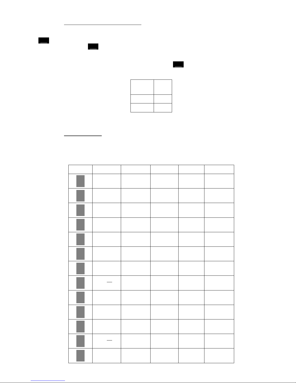
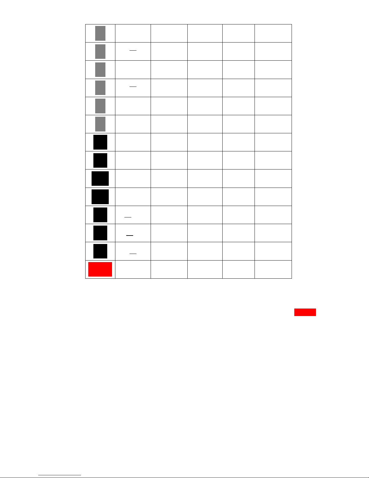
KEY CW BAUDOT ASCII BUFFER DISPLAY
!
1
SP
1
!
1
!
1
!
1
!
1
"
2
"
2
"
2
"
2
"
2
"
2
#
3
SP
3
#
3
#
3
#
3
#
3
$
4
$
4
$
4
$
4
$
4
$
4
%
5
SP
5
LTR
5
%
5
%
5
%
5
&
6
SP
6
&
6
&
6
&
6
&
6
'
7
'
7
'
7
'
7
'
7
'
7
(
8
(.K
8
(
8
(
8
(
8
(
8
)
9
(
9
(
9
(
9
(
9
(
9
0
SP
0
LTR
0
ULL
0
@
00
*
:
SP
:
LTR
:
*
:
*
:
*
:
=
-
=.BT
-
LTR
-
=
-
=
-
=
-
Q
SP
Q
LTR
Q
DC1
Q
Q
QQ

- 17 -
W W W W W W
E E E E E E
R
SP
R
LTR
R
DC2
RR R
T
SP
T
LTR
T
DC4
TT T
Y Y Y Y Y Y
U U U U U U
I
SP
I
LTR
I
HT
II I
_
O
SP
O
LTR
O
_
O
_
O
_
O
@
P
AA
P
LTR
P
@
P
@
P
@
P
A A A A A A
S
SP
S
LTR
SDC3 S S
D D D D D D
F F F F F F
BELL
G
SP
G
BELL
G
BELL
GG
(SOU D SIG.)
G
H
SP
H
LTR
H
BS
HH
(BACK SPACE)
H
J
SP
J
LTR
J
VT
J
K
JJ
(
K
SP
K
LTR
K
(
K
(
K
(
K
\
L
SP
L
LTR
L
\
L
\
L
\
L
+
;
+.AR
VA
LTR
;
+
;
+
;
+
;
Z
SP
Z
LTR
Z
SUB
ZZ Z
X
SP
X
LTR
X
CA
XX X
C C C C C C
V V V V V V
- 18 -
B B B B B B
^
AS
LTR
^
^
^
)
M
SP
M
LTR
M
)
M
)
M
)
M
<
,
HH
,
LTR
,
<
,
<
,
<
,
>
.
SP
.
LTR
.
>
.
>
.
>
.
?
/
?
/
?
/
?
/
?
/
?
/
LF SP LF LF J LF._*
CR SP CR CR M CR and LF
Return.=*
DEL SP LTR DEL ?
ESC
STOP XMIT
SP
STOP XMIT
LTR
STOP XMIT
ESC (
__
BT BT. = LTR = = =
__
K K .( ( ( ( (
__
HH HH / BS <./.H <./.BS
SPACE
BAR SP SP SP SP SP
Table 8
NOTE: 1. Characters in lower part of each column are obtained by pushing each key only;
characters or function in upper part are obtained by pushing each with [SHIFT] key.
2. *: function obtained when CR.LF CANCEL is ON.
Table of contents
Other TONO Conference System manuals


Popular Conference System manuals by other brands

Clear One
Clear One COLLABORATE Versa Room CT quick start guide

Clear-Com
Clear-Com Cellcom instruction manual

Multitech
Multitech MTCDTIP2 Hardware installation guide

Asahi KASEI
Asahi KASEI AKM AK7734 instruction manual

Firecom
Firecom 110 Installation & operation manual

Clear One
Clear One CLOCKAUDIO TS-001 Tech note


