SpectraLink DECT Server 8000 User manual

Spectralink DECT Server 8000
Installation Guide
14184630 version 8.0, K016
September, 2015

Copyright Notice
© 2013 Spectralink Corporation All rights reserved. SpectralinkTM, the Spectralink logo and the
names and marks associated with Spectralink's products are trademarks and/or service marks of
Spectralink Corporation and are common law marks in the United States and various other
countries. All other trademarks are property of their respective owners. No portion hereof may be
reproduced or transmitted in any form or by any means, for any purpose other than the recipient's
personal use, without the express written permission of Spectralink.
All rights reserved under the International and pan-American Copyright Conventions. No part of
this manual, or the software described herein, may be reproduced or transmitted in any form or by
any means, or translated into another language or format, in whole or in part, without the express
written permission of Spectralink Corporation.
Do not remove (or allow any third party to remove) any product identification, copyright or other
notices.
Notice
Spectralink Corporation has prepared this document for use by Spectralink personnel and
customers. The drawings and specifications contained herein are the property of Spectralink and
shall be neither reproduced in whole or in part without the prior written approval of Spectralink, nor
be implied to grant any license to make, use, or sell equipment manufactured in accordance
herewith.
Spectralink reserves the right to make changes in specifications and other information contained
in this document without prior notice, and the reader should in all cases consult Spectralink to
determine whether any such changes have been made.
NO REPRESENTATION OR OTHER AFFIRMATION OF FACT CONTAINED IN THIS
DOCUMENT INCLUDING BUT NOT LIMITED TO STATEMENTS REGARDING CAPACITY,
RESPONSE-TIME PERFORMANCE, SUITABILITY FOR USE, OR PERFORMANCE OF
PRODUCTS DESCRIBED HEREIN SHALL BE DEEMED TO BE A WARRANTY BY
SPECTRALINK FOR ANY PURPOSE, OR GIVE RISE TO ANY LIABILITY OF SPECTRALINK
WHATSOEVER.
Spectralink Corporation,
2550 55th Street,
Boulder CO 80301,
USA
Spectralink Europe ApS,
Langmarksvej 34,
8700 Horsens,
Denmark

14184630 Version 8.0, K016
September, 2015 1
Spectralink DECT Server 8000 Installation Guide
Contents
Spectralink DECT Server 8000 Installation . . . . . . . 3
Installing the Spectralink DECT Server 8000 . . . . . . . . . . . . . . . . . . . . . . . . . . . . . . . . . . . 3
Specifications . . . . . . . . . . . . . . . . . . . . . . . . . . . . . . . . . . . . . . . . . . . . . . . . . . . . . . . . . . . . . . . . . . 3
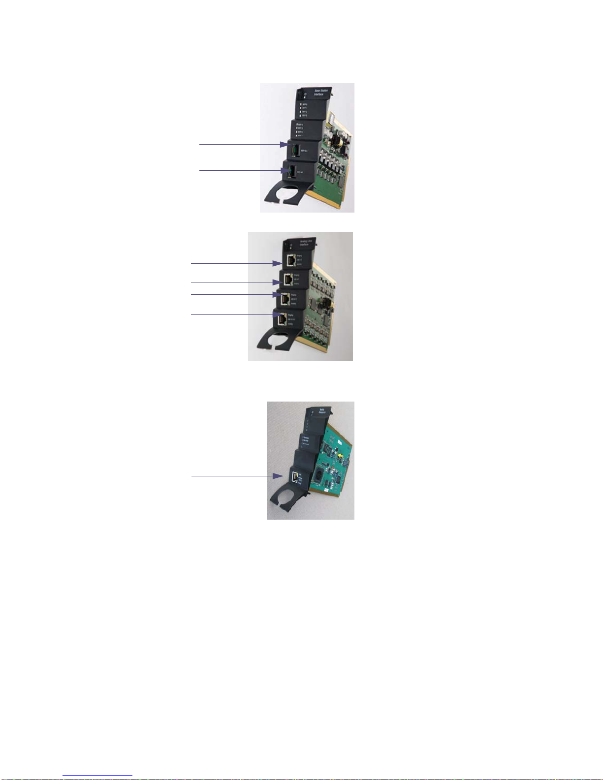
DECT Server 8000 Components . . . . . . . . . . . . . . . . . . . . . . . . . . . . . . . . . . . . . . . . . . . . . . . . . . . 5
Connections . . . . . . . . . . . . . . . . . . . . . . . . . . . . . . . . . . . . . . . . . . . . . . . . . . . . . . . . . . . . . . . . . . . 7
General Installation Information . . . . . . . . . . . . . . . . . . . . . . . . . . . . . . . . . . . . . . . . . . . . . . . . . . . . 8
Installing the Spectralink DECT Server 8000 in a Rack . . . . . . . . . . . . . . . . . . . . . . . . . . . . . . . . . . 9
Installing the DECT Server 8000 on a Flat Surface . . . . . . . . . . . . . . . . . . . . . . . . . . . . . . . . . . . . 11
Installing the Spectralink DECT Server 8000 on a Wall . . . . . . . . . . . . . . . . . . . . . . . . . . . . . . . . . 11
Connecting the Spectralink DECT Server 8000 Cables . . . . . . . . . . . . . . . . . . . . . . . . . . . . . . . . . 12
Installing Interface Cards and CPU Cards . . . . . . . . . . . . . . . . . . . . . . . . . . . . . . . . . . . . . . . . . . . 14
Replacing Components . . . . . . . . . . . . . . . . . . . 20
Component Replacement . . . . . . . . . . . . . . . . . . . . . . . . . . . . . . . . . . . . . . . . . . . . . . . . . . 20
Component Replacement Precautions . . . . . . . . . . . . . . . . . . . . . . . . . . . . . . . . . . . . . . . . . . . . . 20
To Replace an Interface Card . . . . . . . . . . . . . . . . . . . . . . . . . . . . . . . . . . . . . . . . . . . . . . . . . . . . 20
To Replace or Install a New CPU Card . . . . . . . . . . . . . . . . . . . . . . . . . . . . . . . . . . . . . . . . . . . . . 21
Replacing the Backplane . . . . . . . . . . . . . . . . . . . . . . . . . . . . . . . . . . . . . . . . . . . . . . . . . . . . . . . . 21
To Replace an AC Adapter. . . . . . . . . . . . . . . . . . . . . . . . . . . . . . . . . . . . . . . . . . . . . . . . . . . . . . . 21
Regulatory Notices . . . . . . . . . . . . . . . . . . . . . . 22
International Regulatory and Product Information . . . . . . . . . . . . . . . . . . . . . . . . . . . . . 22
United States Federal Communication Commission (FCC) . . . . . . . . . . . . . . . . . . . . . . . . . . . . . . 22
United States Safety Construction Details: . . . . . . . . . . . . . . . . . . . . . . . . . . . . . . . . . . . . . . . . . . 22
CE Mark R&TTE Directive . . . . . . . . . . . . . . . . . . . . . . . . . . . . . . . . . . . . . . . . . . . . . . . . . . . . . . . 22
Canadian Department of Communications . . . . . . . . . . . . . . . . . . . . . . . . . . . . . . . . . . . . . . . . . . 23
Important Safety Instructions and Product Information . . . . . . . . . . . . . . . . . . . . . . . . . 23
Warning . . . . . . . . . . . . . . . . . . . . . . . . . . . . . . . . . . . . . . . . . . . . . . . . . . . . . . . . . . . . . . . . . . . . . 24
Intrinsic safety . . . . . . . . . . . . . . . . . . . . . . . . . . . . . . . . . . . . . . . . . . . . . . . . . . . . . . . . . . . . . . . . 24
Exposure to sunlight, heat and moisture . . . . . . . . . . . . . . . . . . . . . . . . . . . . . . . . . . . . . . . . . . . . 24
Spare parts and accessories . . . . . . . . . . . . . . . . . . . . . . . . . . . . . . . . . . . . . . . . . . . . . . . . . . . . . 24
RF compliance information . . . . . . . . . . . . . . . . . . . . . . . . . . . . . . . . . . . . . . . . . . . . . . . . . . . . . . 25
NOTICES . . . . . . . . . . . . . . . . . . . . . . . . . . . . . . . . . . . . . . . . . . . . . . . . . . . . . . . . . . . . . . . . . . . . 25
Spectralink® Product Warranty Statement . . . . . . . . . . . . . . . . . . . . . . . . . . . . . . . . . . . . . . . . . . 25
END-USER LICENSE AGREEMENT FOR SPECTRALINK SOFTWARE . . . . . . . . . . . . . . . . . . 27

14184630 Version 8.0, K016
September, 2015 2
Spectralink DECT Server 8000 Installation Guide
Analogue Interface Card . . . . . . . . . . . . . . . . . . . . . . . . . . . . . . . . . . . . . . . . . . . . . . . . . . . . . . . . 33
Base Station Interface Card for 4 channels Base Stations . . . . . . . . . . . . . . . . . . . . . . . . . . . . . . 33
Base Station Interface Card for 8 channels Base Stations . . . . . . . . . . . . . . . . . . . . . . . . . . . . . . 34

Spectralink DECT Server 8000 Installation Guide
14184630 Version 8.0, K016
September, 2015 3
Chapter 1: Spectralink DECT Server 8000
Installation
This guide describes how you install the Spectralink DECT Server 8000.
Installing the Spectralink DECT Server 8000
The DECT Server 8000 can be installed in a rack, on a flat surface or on a wall using the
Spectralink DECT Server 8000 Wall Hanger. Before you start the installation, place the DECT
Server 8000 on a stable flat surface in the selected location, and inspect the package for any
damage and report it to the reseller or distributor immediately.
Specifications
Important
•Make sure only authorized persons have access to the equipment.
•Please review all the safety instructions for important safety and
regulatory information.
•The DECT Server 8000 rack can only be installed in a Restricted Access
Location (RAL) where access is limited to service personnel.
Table 1 Physical Dimensions
Physical dimensions
Height 177mm
Width 422 mm
Depth 328 mm
Weight 5.34 kg (excl. power supply)
Table 2 Power Supply
Power supply
AC Input 100-240 VAC, 50/60 Hz

Spectralink DECT Server 8000 Installation Guide
14184630 Version 8.0, K016
September, 2015 4
Table 3 Power Consumption
Power consumption
Typical AC Power Consumption 90 Watt
Max. AC Power Consumption Max 360 Watt
Table 4 Environment
Environment
Operating temperature 0°C - 40°C (22° - 104°F)
Storage temperature -30°C - 70°C (40° - 158°F)
Relative humidity 20% - 80% Non condensing
Operating altitude Up to 2000 m (6,500 ft)
Operating ESD level 4 KV

Spectralink DECT Server 8000 Installation Guide
14184630 Version 8.0, K016
September, 2015 5
DECT Server 8000 Components
The following table contains all Spectralink DECT Server 8000 parts and their part numbers
Table 5 DECT Server 8000 Components
Picture Description Part Numbers
Base Station Interface card (8 base
stations) 0233 9100
Analogue Interface card (16 lines) 0233 9200
Analogue Interface card (8 lines) 0233 9220
CPU card with link option
0233 9800
Includes two terminator
connectors.
CPU card without link option 0233 9900

Spectralink DECT Server 8000 Installation Guide
14184630 Version 8.0, K016
September, 2015 6
Media Resource Card 0233 9700
Link cable 0233 9400
EU rack
US rack
UK rack
0233 8900
0233 8901
0233 8902
Includes mains adapter and mains
cable.
Wall hanger 0250 0200
Mains adaptor 8476 9902
EU mains cable 8468 7013
UK mains cable 8468 7014
Table 5 DECT Server 8000 Components
Picture Description Part Numbers

Spectralink DECT Server 8000 Installation Guide
14184630 Version 8.0, K016
September, 2015 7
Connections
Figure 1 CPU Card Connections
The USB connection is not active in this release. Once it is active, it can be used as an alternative
to the RS232 connection.
US mains cable 8468 7015
Terminator connector 0250 0300
RS232 cable 13281100
Note
Link connections must not be left open. You must either plug in a link cable
or a terminator connector for protection and for stable functionality.
Table 5 DECT Server 8000 Components
Picture Description Part Numbers
Link upwards
Link downwards
USB
Ethernet
RS232

Spectralink DECT Server 8000 Installation Guide
14184630 Version 8.0, K016
September, 2015 8
Figure 2 RJ45 Connections for Base Stations
Figure 3 RJ45 Connections for AB Lines
Figure 4 Media Resource Card Connection
General Installation Information
The maximum number of DECT Server 8000 units that can be linked together depends on the
mounting method and the maximum length of the link cable:
A: RJ45 Connection
B: RJ45 Connection
A RJ45 Connection
B RJ45 Connection
D RJ45 Connection
C RJ45 Connection
A Ethernet

Spectralink DECT Server 8000 Installation Guide
14184630 Version 8.0, K016
September, 2015 9
•Rack mount: 8 units
•Flat surface mount: 2 units
•Wall mount: 1 unit
General Mounting Safety Precautions
•Keep the area around the Spectralink DECT Server 8000 clean and free of clutter.
•Decide on a suitable location for the equipment rack that will hold the Spectralink DECT Server
8000 unit. It should be situated in a clean, dry, and dust-free area that is well ventilated. Avoid
areas where heat, electrical noise, and electromagnetic fields are generated.
•Place it near an earthed power outlet.
•Place the power supply unit externally to the equipment.
Installing the Spectralink DECT Server 8000 in a Rack
Before you start installation take notice of the following safety precautions.
Rack mounting Safety Precautions.
• Important Always ensure proper rack earthing. Electrical shock hazards from the
telecommunication network and AC mains are possible with this equipment. To minimize risk
to service personnel and users, the system must be connected to an outlet with a third-wire
earth connection.
•Ensure that the leveling jacks on the bottom of the rack are fully extended to the floor with the
full weight of the rack resting on them.
•In a single rack installation, stabilizers should be attached to the rack.
•In multiple rack installations, the racks should be coupled together.
•Always make sure the rack is stable before extending a component from the rack.
•You should extend only one component at a time - extending two or more simultaneously may
cause the rack to become unstable.
•Before you install the rails, determine the placement of each component in the rack.
•Install the heaviest components on the bottom of the rack first, and then work up.
•Always keep the rack’s trays and boards closed when not servicing, to maintain proper
cooling.
Important
Always ensure proper rack earthing. Electrical shock hazards from the
telecommunication network and AC mains are possible with this equipment.
To minimize risk to service personnel and users, the system must be
connected to an outlet with a third-wire earth connection..

Spectralink DECT Server 8000 Installation Guide
14184630 Version 8.0, K016
September, 2015 10
•The rack ambient temperature may rise beyond room ambient temperature. in a multi unit
assembly, measures must be taken to ensure the Spectralink DECT Server 8000 ambient
temperature does not exceed the maximum operating ambient temperature of 40
°Celsius/104°Fahrenheit. The backplane temperature inside the Spectralink DECT Server
8000 can be up to 13°Celsius/24° Fahrenheit higher than the ambient temperature.
•To ensure ventilation, always leave 2/3 U between the Spectralink DECT Server
8000Spectralink DECT Server 8000 units any other units mounted in the rack.
To Install the Spectralink DECT Server 8000 in a Rack
You can install the Spectralink DECT Server 8000 in a rack using one of the two following
methods:
1Install the brackets supplied by the rack manufacturer on each side of the rack on which the
Spectralink DECT Server 8000 is placed. Secure the system by fastening four screws to the
rack on the front panel.
- OR-
1Install a shelf supplied by the rack manufacturer on top of which the Spectralink DECT Server
8000 is placed. Secure the system by fastening four screws to the rack on the front panel.
Figure 5 Rack Installation

Spectralink DECT Server 8000 Installation Guide
14184630 Version 8.0, K016
September, 2015 11
Installing the DECT Server 8000 on a Flat Surface
Before you start installation take notice of the following safety precautions.
Flat Surface Mounting Safety Precautions
•Ensure the surface can support the weight of the unit.
•Never install the Spectralink DECT Server 8000 on the floor.
•Never place anything, except ONE additional Spectralink DECT Server 8000 unit, on top of
the Spectralink DECT Server 8000. The top plate must be free to allow sufficient cooling.
To Install the DECT Server 8000 on a Flat Surface
1Remove the Spectralink DECT Server 8000 from its package.
2Before placing the unit, carefully turn it upside down and mount the four rubber pads supplied
in the package. One must be placed at each corner of the bottom plate.
3Place it on a clean, flat, horizontal surface.
Installing the Spectralink DECT Server 8000 on a Wall
Before you start installation take notice of the following safety precautions.
Wall Mounting Safety Precautions
•Ensure the wall quality is good enough for holding the unit. Avoid high-porous surfaces, joints
and similar.
•Never use countersunk screws.
•Leave at least 10 centimeter of free air above the unit for ventilation.
To Install the Spectralink DECT Server 8000 Using the Wall Hanger
For free hanging installations, you use the wall hanger.
1Find a suitable spot on an even closed-textured surface. The unit should be placed minimum
1 meter above ground surface and minimum 20 centimeter from any corner.

Spectralink DECT Server 8000 Installation Guide
14184630 Version 8.0, K016
September, 2015 12
Figure 6 Wall hanger positioning
2Mount the wall hanger securely using four screws. Use rawlplugs, expansion bolts, or other
appropriate fastening methods in relation to the wall material.Remove any drilling dust.
3Fit the DECT Server 8000 into the wall hanger, and fasten the two front screws.
Figure 7 Fitting the Spectralink DECT Server 8000 into the wall hanger
Connecting the Spectralink DECT Server 8000 Cables
When the Spectralink DECT Server 8000 has been mounted, the cables can be connected.
DECT
Server 8000

Spectralink DECT Server 8000 Installation Guide
14184630 Version 8.0, K016
September, 2015 13
Cable Safety Precautions
Before you connect the cables, ensure to take the following electrical safety precautions.
•Always use an earthed socket for power.
•Use a power cord with protective earth (PE) connection suitable for the country where it is
being used and with the appropriate local approvals.
•If using a rack, always ensure proper rack earthing
•Power supply cables must be connected prior to connecting any interface cables.
•The interface cables must be removed before any interface card is removed or replaced.
•When unplugging power, unplug AC mains power first before unplugging the power connector
from the Spectralink DECT Server 8000.
•The AC adapters must never be hanging by their own weight in the AC mains connector or the
output connector.
To Connect Power Cables
The Spectralink DECT Server 8000 has four power plugs on the back panel behind the sliding
doors:
•System Power Backup
•System Power Primary
•4+ BIF Power Backup
•4+ BIF Power Primary
Figure 8 DECT Server 8000 Power plugs
The unit configuration determines which plugs to use. Connect the plugs according to the following
table.
S
ys
t
em
0V 19V
Backup Primary Backup Primary

Spectralink DECT Server 8000 Installation Guide
14184630 Version 8.0, K016
September, 2015 14
1Plug a suitable power cord into the AC power adapter.
2Insert the AC power adapter output connector firmly into the socket on the Spectralink DECT
Server 8000 so that the retention clip snaps to the plug.
3Plug the AC power adapter into mains.
4If more than one AC power adapter is to be connected, the primary system power must be
connected first, the rest does not have to be done in any particular order.
5When powering down the unit, ALL power connectors must be unplugged to ensure the unit
is completely powered off.
If more than two AC power adapters are used, these must be kept on a flat surface (same
requirements as for the Spectralink DECT Server 8000 unit). In a rack installation the power
adapters can be kept on a tray installed for the purpose provided that the ambient temperature is
below 32ºCelcius/89,6º Fahrenheit, and they have free air surrounding them.
Installing Interface Cards and CPU Cards
Before you install an interface or a CPU card ensure to take the following precautions.
Safety Precautions
Cards contain static sensitive circuitry and may be destroyed or damaged by electrostatic
discharge (ESD).
•Make sure you re using proper ESD equipment to prevent damage to the system.
•Fill all empty slots with blanking front plates to close the front.
To Install Interface Cards
1With two hands, gently slide the interface card into the unit. Give it a gentle push on the last
centimeter so that it enters the backplane connector properly.
Avoid pushing on the front connectors - push only on the plastic parts at the top and bottom.
Table 6 Cable Plugs Overview
#Nbr BIF
Cards Redun-
dancy SYS PWR
Primary SYS PWR
Backup 4+ BIF PWR
Primary 4+ BIF PWR
Backup
BIF Card
Place-
ment
1≤4 No Connect No Connect No Connect No Connect Slot 5-8
2≤4 Yes Connect Connect No Connect No Connect Slot 5-8
3>4No Connect No Connect Connect No Connect Slot 1-8
4>4Yes Connect Connect Connect Connect Slot 1-8

Spectralink DECT Server 8000 Installation Guide
14184630 Version 8.0, K016
September, 2015 15
Figure 9 Installing Interface Cards
2Plug the interface cables into the card as described in the section “Conntecting Interface
Cables”.
To Install CPU Cards
1Ensure that the Spectralink DECT Server 8000 is powered off completely.
2With two hands, gently slide the card into the unit. Give the card a gentle push on the last
centimeter so that it enters the backplane connector properly.
Avoid pushing on the front connectors - push only on the plastic parts at the top and bottom.

Spectralink DECT Server 8000 Installation Guide
14184630 Version 8.0, K016
September, 2015 16
Figure 10 Installing CPU card
3Plug the interface cables into the card as described in the section “Connecting Interface
Cables”.
4Connect the link cable if required for linking more units together. If no link cables are required,
insert terminator connectors.
5Connect the Spectralink DECT Server 8000 to a PC using theRS232 cable.
6Connect the power and reboot the unit.
Connecting Interface Cables
The front interface of the Spectralink DECT Server 8000 is provided with connectors for the
different interfaces provided. Please see the Spectralink DECT Server 8000 Configuration Guide
for the actual pin-out of the different connectors.
The cables can be harnessed in two ways as shown in the following figures depending on the
installation requirements.

Spectralink DECT Server 8000 Installation Guide
14184630 Version 8.0, K016
September, 2015 17
Figure 11 Harnessing cables to the back and out

Spectralink DECT Server 8000 Installation Guide
14184630 Version 8.0, K016
September, 2015 18
Figure 12 Harnessing cables to the side and out.
Regardless of which way is used for harnessing, you must guide the cables through the opening
in the plastic front. This ensures safe retention of the cable.
Table of contents
Popular Conference System manuals by other brands

Mitel
Mitel Navigator 3300 ICP General Information Guide

nVent RAYCHEM
nVent RAYCHEM Elexant 9200i manual

AT&T
AT&T MERLIN 206 user guide

Codian
Codian IP VCR 2200 Series installation guide

Crestron
Crestron UC-MX50-Z-UPGRD quick start

Danish Interpretation Systems
Danish Interpretation Systems DCS 6000 user manual