manuals.online logo
Brands
  1. Home
  2. •
  3. Brands
  4. •
  5. Fein
  6. •
  7. Drill
  8. •
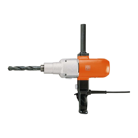
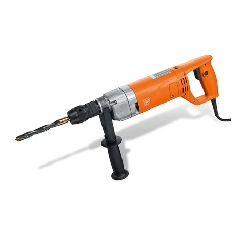
  9. Fein ASz 648 d User manual

Fein ASz 648 d User manual

This manual suits for next models

5

Other Fein Drill manuals

Fein DDSk 111 User manual

Fein

Fein DDSk 111 User manual

Fein KBM 32Q User manual

Fein

Fein KBM 32Q User manual

Fein KBU 35 PQ Setup guide

Fein

Fein KBU 35 PQ Setup guide

Fein HandyMaster ASB 14V User manual

Fein

Fein HandyMaster ASB 14V User manual

Fein KBM 65 U User manual

Fein

Fein KBM 65 U User manual

Fein KBC35 User manual

Fein

Fein KBC35 User manual

Fein BOS 16 User manual

Fein

Fein BOS 16 User manual

Fein ASy 630 User manual

Fein

Fein ASy 630 User manual

Fein BOP6 User manual

Fein

Fein BOP6 User manual

Fein DSc 648 User manual

Fein

Fein DSc 648 User manual

Fein KBE 52-2 M Setup guide

Fein

Fein KBE 52-2 M Setup guide

Fein KBH25-2U Series User manual

Fein

Fein KBH25-2U Series User manual

Fein KBU 35 MQ User manual

Fein

Fein KBU 35 MQ User manual

Fein HandyMaster ABS 12V Quick start guide

Fein

Fein HandyMaster ABS 12V Quick start guide

Fein 7 113 18 61 User manual

Fein

Fein 7 113 18 61 User manual

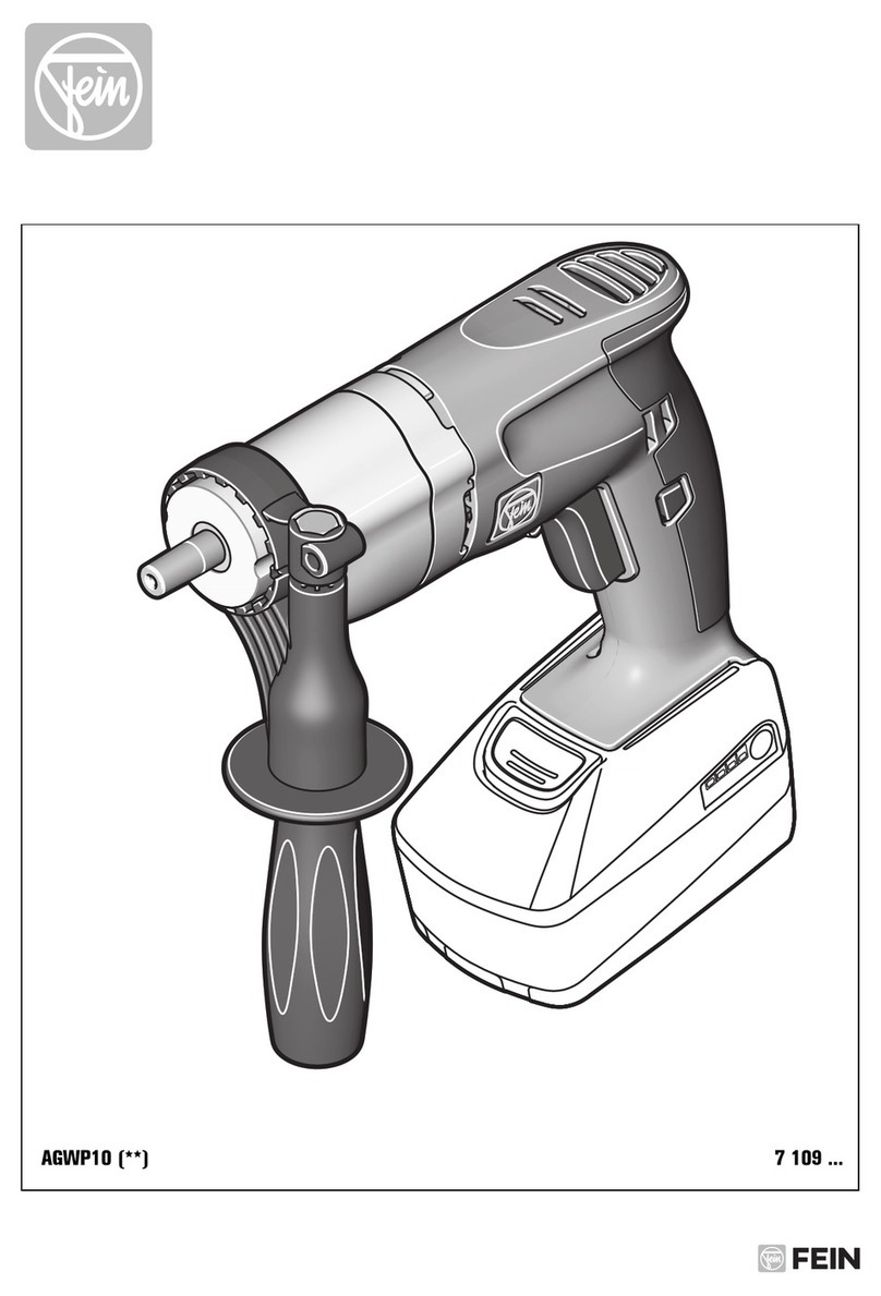
Fein AGWP10 User manual

Fein

Fein AGWP10 User manual

Fein ASCT18 User manual

Fein

Fein ASCT18 User manual

Fein ABS 18 User manual

Fein

Fein ABS 18 User manual

Fein ASge636 User manual

Fein

Fein ASge636 User manual

Fein ASKEU 636 Kin User manual

Fein

Fein ASKEU 636 Kin User manual

Fein KBE 35 Series User manual

Fein

Fein KBE 35 Series User manual

Fein KBM 50 Q User manual

Fein

Fein KBM 50 Q User manual

Fein KBM 52 U User manual

Fein

Fein KBM 52 U User manual

Fein ABS 14 Setup guide

Fein

Fein ABS 14 Setup guide

Popular Drill manuals by other brands

Stanley FatMax FME140 Original instructions

Stanley

Stanley FatMax FME140 Original instructions

Black & Decker MATRIX BDCDMT120C instruction manual

Black & Decker

Black & Decker MATRIX BDCDMT120C instruction manual

DeWalt D25134 manual

DeWalt

DeWalt D25134 manual

Skil 2431 Original instructions

Skil

Skil 2431 Original instructions

Bort 93728410 user manual

Bort

Bort 93728410 user manual

GreenWorks DDG407 Operator's manual

GreenWorks

GreenWorks DDG407 Operator's manual

Panasonic EY7460 - DRILL DRIVER 21.6V operating instructions

Panasonic

Panasonic EY7460 - DRILL DRIVER 21.6V operating instructions

Mueller E-5 operating instructions

Mueller

Mueller E-5 operating instructions

Bosch GSB Professional 18-2 RE Original instructions

Bosch

Bosch GSB Professional 18-2 RE Original instructions

Clarke CON18LI Operation & maintenance instructions

Clarke

Clarke CON18LI Operation & maintenance instructions

Makita 8280D technical information

Makita

Makita 8280D technical information

Stanley SCH20 user manual

Stanley

Stanley SCH20 user manual

Makita BDF456 instruction manual

Makita

Makita BDF456 instruction manual

Makita LXFD01 instruction manual

Makita

Makita LXFD01 instruction manual

Black & Decker LDX220 instruction manual

Black & Decker

Black & Decker LDX220 instruction manual

GMC HD1400K instruction manual

GMC

GMC HD1400K instruction manual

POWERBOR PB1000E owner's manual

POWERBOR

POWERBOR PB1000E owner's manual

Festool T18+3 instructions

Festool

Festool T18+3 instructions

manuals.online logo
manuals.online logoBrands
  • About & Mission
  • Contact us
  • Privacy Policy
  • Terms and Conditions

Copyright 2025 Manuals.Online. All Rights Reserved.

I
l
/,
I
ASz
648
To
be handed to the workshop!
Operating instructions
for the double insulated and radio suppressed
A.C. Electric Drill type ASz
648
d, b, a
and for ASz 7
48
~'
b, a
(42
Volts}
1.
Technical
Data
Type
of current: -(A.C.)
Double insulation
without
e~rth
wire according to VDE 0740
Radio suppressed according
to
VDE
0875
Capacity
in R.P.M.
Tapered
Net
weight
Type steel light metal
Input
Output
Spindle
Ill.
I mm
Ill.
mm full load I no load Watts Watts lbs I kg
ASz
648 d/748 d '/4 6 9/s 10 1600
ASz
648 b/7
48
b 3/s 10 9/
16
15
700
ASz
648 a/7
48
a '/2 13 s;4 20 440
....
,
...
j
Use
U n i
,ersa
l C r
c:
c::o
tyDe
S:.;'j·]
ln
steao
cf
at
or
t
y,::u__;
of
c;
r
eose
l
2.
Ope
ation
- t
------·-·
----..J
Remove all signs
of
grease from chuck.
Main voltage must correspond
to
the operation voltage marked on the
rating plate. Switch in
"Off"
position.
To
prevent
the
overbridging
of
the
insulation
no
additional
mark-
ing
plates
and
signs
must
be
riveted
or
screwed.
We recommend the use
of
transfers.
3.
Maintenance
and
lubrication
Pull
out
plug
before
carrying
out
any
maintenance
work.
After
300
working
hours
clean air openings
of
the motor housing.
Blow
out
motor
with
dry
pneumatic air.
Renew the gear grease. Loosen screws (50, 51)
and
take off gear head.
Only
use the Fein special grease
FG
12.
After
900
working
hours
clean machine thoroughly. Rinse gears in
clean solvent
and
pack
with
fresh grease
FG
12. Rinse ball bearings
in clean solvent
and
pack
with
fresh grease for ball bearings
FK
3.
Dismantling see
paragraph
4.
BE
229/e
BX
11.69 ·
2600 500 300 B 16 6.4 2.9
1100 500 300 B 16 6.4 2.9
700 500 300 B 16 6.4 2.9
Type
of
grease
Quantity
I
Order
contents
Reference oz. g
FG
12
for gearing
:5£J
{;V MZ 60-3/FG 12 3 90
FK
3 for ball 1/a between MZ 60-2/FK 3 1 1/a 40
bearings inner
and
outer ring
Clean
electric
parts
only
dry.
Replace carbon brushes when they have
worn
down
to
7 mm (0.28 in).
To
replace brushes see
paragraph
4,
sections 1
and
3.
Only
use
Fein
carbon
brushes.
After
fitting new brushes
check
that
they move easily in their holder.
Run
tool unloaded for about
15
min.
Check connection cable
at
regular intervals.
To
replace unscrew screws
(20, 21), remove cover (19), loosen screws (16)
of
the terminal clamp
and
clamp off cable from switch (12).
No
claims can be entertained for damage due
to
negligent main-
tenance
and
inadequate lubrication.
45
39
I
l
O"e
'.
t?£i!!fa 1 •
~
~
e"
T
==~~==©
81•
51
0-52
fjli;;;;;;;;;;;;;;;;;;;;;;;;;;;;;;~
©
7
0
50
81
@--52
l'
~
s=w
4t
--------------.,
I
I
I
I
I
47
48 I
I
, I
n-e)
~
I
I
I
I
I
I
I
I
,--
_____
____
...,..
__
__
---------
--
-
---
----.---------
_.J
I
I
I
I
I
I
I
I
I
t
I
I
I
I
I
I
I
I
!_
___
36
53
54
25-29
55
10
•
---
-
--;
I
i
I
I
I
..
I
I
I
I
:
I
I
r----------------------------------+----------------------------------+-----------------------------------+-----------------------------------·--------------------J
t
:
I
i
I
r-------
--•---
---
-------
---_,..
__________
,
I
I
I
I
I
:
-}
I
I
I
I
I
i
L
__
_
7 9
........
14
l
4
l
12
21
~
-
-----
-
'-=:7
'
~
Component
Parts
0
z
Order
>-
...
&
Description
....
Reference
o!
~
0
z
Order
>-
Description
...
&
....
Reference
o!
~
I
1-21
MK
2-22-2 1
motor
housing,
assembled
only
for
ASz
648 a
1-12
MK
2-22-1 1
motor
housing, assembled
15-21 without cable 36-48 LA 8-121-2a 1
drill
head,
assembled
1
MK
2-22 1
motor
housing 37-48 LA 8-121-1a 1 outer bearing, assembled
2,
3
EZ
12-52-1 2
carbon
holder, assembled 44
ZR
15-30x1 1 gear wheel,
43
teeth
2 EZ 12-52 2 carbon holder
46
ZR
16-12x1 1 countershaft pinion, 9
teeth
3
FD
7-32 2 spring 47
ZR
15-28x1 1 countershaft gear wheel, 29 teeth
4
SR
41-MJ,SxiO 4 fillister
head
screw
53
RJ
12-58 1 sealing ring
5
EZ
11-67 2 carbon b!-ush
6
SR
3-M4x6 2 fillister head screw
[ 7
state
type
1 pole housing
with
winding, assembled
and
voltage
only
for
ASz
648 b
36-48 LA 8-121-2b 1
drill
head,
assembled
8
PT
37-13 2 securing
plate
37-48 LA
8-121-lb
1 outer bearing, assembled
9
SR
1-M4x60 2 hexagon screw
10
]S
28-10 1
air
conducting ring
12 · EZ 1-73 1 switch, 2 poles
13
JS
13-90 1 cable protecting sleeve
44
ZR
15-29x1 1 gear wheel,
38
teeth
46
ZR
16-11x1 1 countershaft pinion, 13
teeth
47
ZR
15-28x1 1 countershaft gear wheel, 29 teeth
53
R]
12-58 1 sealing ring
14
EZ
7-133 1 ·cable
15
PT
31-21 1 cable clamping bridge
16
SR
3-M3,5x10 2 fillister
head
screw
only
for
ASz
648 d
17
EZ
22-57 1 capacitor
18
SR
3-M3,5x5 1 fillister
head
screw
19
PT
28-50 1 cover
36-48 LA 8-121-2 d 1
drill
head,
assembled
37-48 LA 8-121-1 d 1 outer bearing, assembled
20 SR 6-M3,5x12 1 -countersunk screw
21
SR
3-M4x18 3 fillister
head
screw
44
ZR
15-34x1 1 gear wheel, 35
teeth
46
ZR
16-17x1 1 countershaft pinion, 18
teeth
25
-
29
state
type 1
armature
with
winding, commutator
a
nd
voltage
and
fan, balanced
47 ZR15-33x0,75 1 countershaft gear wheel, 38 teeth
53
RJ
12-65 1 sealing ring
29 FL 4-10 1 fan
36 LA 6-178 1 intermediate
be~ring
37 LA 8-121 1
outer
bearing
42
Volts
39
WB
1-64 1 drill
shaft
1-21 MK 2-22-6 1
motor
housing, assembled
40
LK
16-3 1 groove ball bearing
41
BU
1-223 1 bushing
42
RJ
27a-35 x19,5 1 Nilos ring
1-12
MK
2-22-5 1 motor housing, assembled
15-
21
without cable
2, 3
EZ
12-53-1 2 carbon holder, assembled
2 EZ 12-53 2 carbon holder
43
LK
1-8 1 groove ball bearing 5
EZ
11-72 2 carbon brush
45
RJ
18-32 1
threaded
ring
48
LK
1-2 2 groove
ball
bearing 14
EZ
6-110
--
1--
' cable
50
SR
33-M5x55 2 socket he
ad
cap screw
51
SR
33-M5x65 2 socket
head
cap screw
Accessories
52
PT
5d-M5 4 securing
plate
EZ 11-67 2 carbon brush only for 220 V
54
LK
16-46 1 groove ball bearing EZ
11
-72 2 carbon brush only for 42 V
55
LK
16-10 1 groove ball bearing z10-10 1 he
xa
gon socket wrench
4.
Dismantling
1. Loosen screws (20, 21), remove
handle
cover (19).
2.
Clqmp off cable from switch (12), clamp off capacitor (17)
at
motor
housing (1).
3.
Clamp
off carbon cable, pull carbon brush (5)
out
of
holder.
4.
Loosen screws (50, 51), remove
and
dismantle outer bearing (37)
with
intermediate bearing (36).
Draw
out
drill shaft (39).
5.
Pull
armature
out
of
motor
housing.
6.
Pull
air
conducting ring (10)
out
of
motor
housing, loosen screws
(9),
take
out
pole housing (7).
Re-assemble in reverse sequence.
S.
Stationary
use
in·
the
bench drill stand
If
the machine
is
constantly used in
the
bench drill
stand
remove drill
after
50 working hours
and
turn
by
180° just
after
operation
to
lubricate
the
pinion.
After
150 working hours check
the
lubrication
of
the pinion. Loosen screws (50, 51)
and
take
off
gear
head
.
6. Repair and Spare Parts
We recommend
our
Fein Service Stations
to
carry
out
all
overhaul
and
repair
work
quickly
and
expertly.
Please
quote
Order Reference
when
ordering spare parts
or
send
in
sample
part, stating
the
type
of
the
machine.
We
draw
your
attention
to
the need to
carry
out
a high voltage test
in accordance
with
your
local regulations (or
VDE
regulation 0740)
before
taking
a tool into service
after
any
repair
carried
out
by
your
own staff.
I I
(