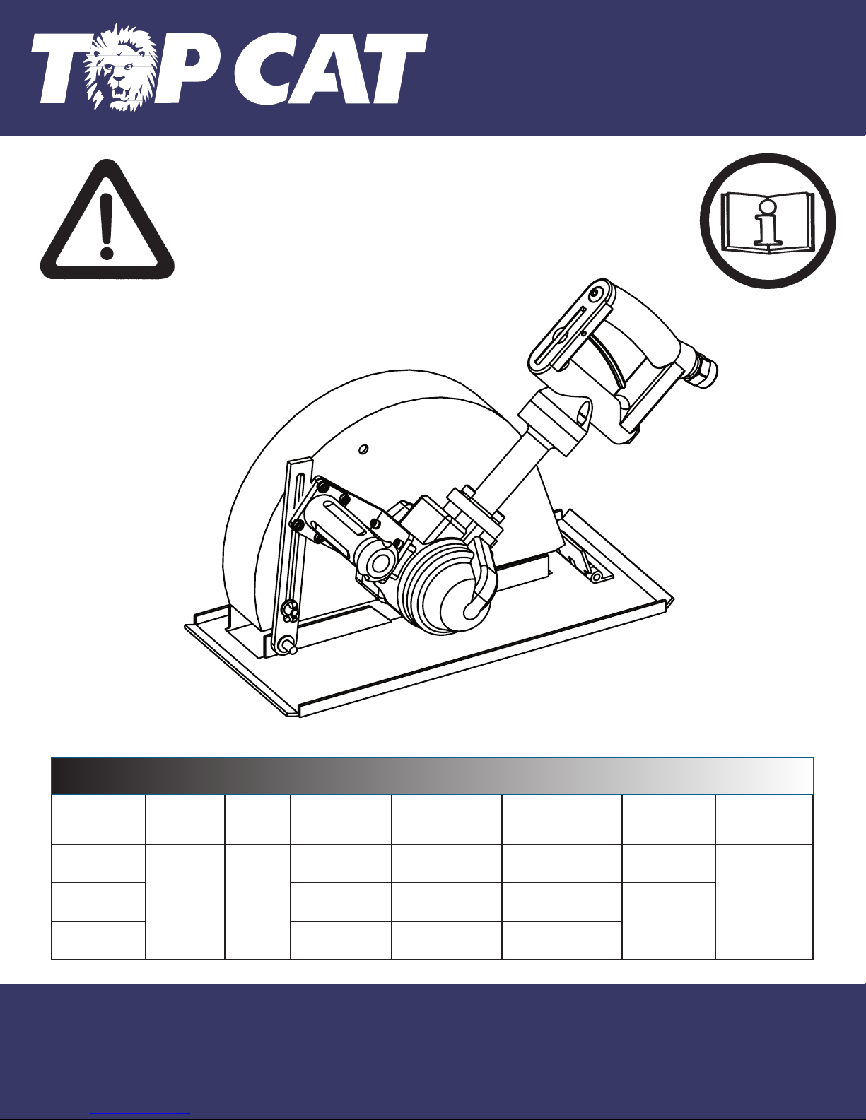
TOP CAT 65VBW-9" Guard Instructions for use
General Operators Instructions
and
Maintenance Manual
65VBW
Series Saws
Top Cat ® Air Tools, Manufactured by T.C. Service Co.
38285 Pelton Road, Willoughby, OH 44094 U.S.A.
Ph: (440) 954-7500 or (800) 321-6876 ● Fax: (440) 954-7118 or (877) 800-3589
E-Mail: [email protected] ● Web Site: www.tcservice.com
Read Safety Recommendations Before Operating Tool
Model
Number
Power
Output
Rated
Speed Weight Blade Diameter Maximum Depth
of Cut
Arbor Hole
Size
Working Air
Consumption
65VBW-9”
Guard
4 H.P.
(3000 KW)
4000-
6000
R.P.M.
26.3 Lb.
(11.9 Kg)
9 Inch
(230 mm)
2.5 Inches
(64 mm)
5/8 Inch
(16 mm)
50 cfm
(23.6 L/S)
65VBW-12”
Guard
28.3 Lb.
(12.8 Kg)
12 Inch
(300 mm)
3.5 Inches
(89 mm) 1.0 Inch
(25 mm)
65VBW-14”
Guard
30.9 Lb.
(14.1Kg)
14 Inch
(360 mm)
4.3 Inches
(109 mm)
65VBW Series Saws
65VBW

This is meant to highlight sections of safety standards published by the American National Standards
Institute and the Occupational Safety and Health Administration. This is not meant to replace those
standards but only highlight certain areas.
When care is taken to ensure that the right tool is operated properly, and safety and maintenance
procedures are followed, accidents can be avoided. Read and follow all instructions and directions.
Comply with all rules governing the use of power tools, personal protective equipment and equipment
guards.
Remember - machines, attachments and accessories must be used only for the purpose for which
they were designed. Safety reasons and product liability prohibit any modifications to tools. Any
attachments or accessories must be agreed to in advance with an authorized technical representative
of T.C. Service Co.
Operators Instructions and Safety Precautions
The grinding equipment must be approved
for the rated speed of the machine. The
rated speed, marked on the machine,
should not be exceeded. Be sure to learn
the proper handling and storage of abra-
sive wheels and inserted tooling.
Inspect the wheel guard for any signs of
wear and that it is properly mounted to
the tool. Any guard showing signs of wear
such as bends, chips, nicks, or cracks
should be replaced.
Check hose size and air pressure. The air pressure at the tool shall
not exceed 90 psi (6.2 bar). All hoses should be inspected regularly
and kept away from heat, oil and sharp edges. Be sure the tool is
secured to the air hose.
Measure the speed of grinders every 20 hours of actual use or once
per week, whichever comes first.
Tachometers must be checked and calibrated on a regular basis
according to the manufacturers recommendations
Measure speed of all types of grinders after maintenance or repair,
whenever a grinder is issued from the tool crib and at each wheel
change. Several readings should be taken.
This form of inspection should be made with the grinding wheel or
tooling removed.
Always wear eye and hearing protection, and when
necessary, other personal protective equipment such
as gloves, an apron, and helmet. Properly fitted protec-
tive clothing cushion the operator from vibration expo-
sure and help prevent minor scrapes that might occur
as a result of guiding the tool along the work piece.
Additional information on eye protection is available in
the following national regulatory standards.
1) Federal OSHA Regulations 29 CFR, Section
1910.133 (Eye and Face Protection)
2) ANSI Z87.1 (Occupational and Educational Eye and
Face Protection)

Safety in Operation
Proper mounting of grinding
wheels and inserted tooling is
crucial to safe operation and
efficient working conditions.
Ensure the exhaust air is
directed away from bystanders.
Disconnect the tool from the air
supply before doing any service. This
prevents accidental start-ups. Do not
disassemble or adjust the governor.
The governor is guaranteed for the
life of the tool, if not abused.
Airborne particulate resulting
from the grinding process
can cause hazards. Wear
appropriate protective
equipment.
The safety procedures for operating air tools are everyone’s responsibility. The following lists several
aspects of air tool safety that should be considered during operation. Please be aware of the these
aspects and report any unsafe practice you see to a supervisor or safety officer immediately.
1) Start any new blade or wheel under a bench and away from bystanders. (Run for a minimum of one
minute.)
2) When starting a cold/new wheel, apply to the work slowly, allowing the wheel to warm gradually.
3) Support the work piece properly.
4) When cutting off, support the work piece so that a jamming of the blade or wheel does not occur. (A
Slot shall remain constant or become wider during operation.)
5) If a jamming of the blade or wheel does occur during a cutting off operation, shut the air supply off to
the tool and ease the wheel free. (Inspect the wheel for damage before continuing operation.)
6) Ensure that sparks from the process do not create a hazard to the eyes or will ignite the environment.
7) Grinders and saws shall not be used in potentially explosive atmospheres.
8) Pneumatically driven tools are not generally insulated from coming in contact with electrical sources.
Be sure to avoid contact with wires or other possible current carrying sources.
9) The operator must check that no bystanders are in the vicinity.
10) Remember that there is a running on after the throttle has been released.
11) If a saw or grinder fitted with an blade or abrasive wheel is dropped, the blade or wheel must be
thoroughly examined before re-use.
12) Disconnect the tool from the air source before servicing and changing blades or wheels.
13) Release the control device in case of interruption of air supply.
14) Always keep the tool in a clean, dry place when not in use.
15) Beware of loose hair and clothing so as not to become tangled or trapped during operation.
16) Unexpected tool movement, or breakage of wheel or blade, may cause injury.
17) Unsuitable postures may not allow counteracting of normal or unexpected movement of a power
tool. (A working position shall be adopted which remains stable in the event of a break up of blade or
wheel.)
18) Do not hold the tool near the body when operating.
19) Keep a firm grip on the tool body during operation.
20) Immediately shut off the tool if unusual vibration or sound is detected. Remove and inspect the
blade or wheel and check the tool speed (RPM) with an accurate tachometer. Use of over-speeding
grinder or unbalanced blades or wheels may result in serious injury.
21) Stay alert. Do not use the tool while under the influence of alcohol, drugs or medication.

Disassemble
1. Disconnect tool from air supply and remove all blades, wheels, removable flanges, and
accessories.
2. Secure tool in a vise with motor axis in horizontal position. Clap onto the spade handle (550-H-3).
3. Remove three screws (700-47A), three lock washers (700-46) and wheel guard (650-SV-9, 650-S-
102, or 650-S-104 ). Remove guard.
4. Remove screw (591104). Remove outer cover of gear case (662-3).
4. Grasp motor output and pull motor assembly from case. The motor assembly must be kept straight
to pull from case easily. Try to maintain alignment as best as possible. Remove from vise.
5. Secure motor assembly into vise vertically with governor upward. Clamp onto flats of wheel flange
(550-12B) or, using brass jaws in vise, the spine on the output spindle (650-14-A).
6. Remove governor (AA-550-XX) with a wrench. (Left-hand thread)
7. Remove lock ring (1000-5) using snap ring pliers. Remove from vise.
8. Clamp motor assembly into vise with output pointed down. Clamp lightly onto the cylinder (700-11)
and rear endplate (700-16). Place a small punch into the center of the motor spindle (650-8 or 650-
14-A) where the governor was removed. Tap lightly on end of punch, and drive the spindle through
the rear bearing (700-9) (Be sure not to damage threads on the rear of the spindle.) (Take care not to
drop the spindle assembly when it becomes free.) Remove from vise.
9. Use a small screwdriver to push the rear bearing out of the rear endplate.
10. Remove the cylinder (700-11), the rotor blades (700-13) and the rotor (700-12).
11. On 9” guard models, leave the key (700-15) in the key slot for now. Clamp spindle holder (1100-
650) into vise vertically. Align key slot in holder with key of spindle and slide spindle assembly
through. Remove wheel flange (550-12B). Remove from vise. Remove key (700-15) and lift off front
end plate (700-10).
12. On 12” and 14 “ guard models, remove snap ring (591132) using snap ring pliers.
14. Support front bearing assembly on a suitable drill block. Press spindle through front bearing (700-
9) with arbor press.
15. Remove snap ring (550-21) using snap ring pliers. Lift out bearing cover (550-25).
16. Press out front bearing (700-7) from front bearing support (650-1-BTB).
17. To check throttle valve, unscrew throttle valve cap (700-S-26). Lift out valve spring (600-51) and
throttle valve (560-13). Replace o-ring (200-9) if cracked of torn.
Assembly
1. Be sure all parts are clean and free of any abrasive.
2. Press front bearing (700-7) into front bearing support (650-1-BTB).
3. Slip bearing cover (550-25) into front bearing support and onto front bearing.
4. Install snap ring (550-21) into groove of front bearing support with use of snap ring pliers.
5. Support front bearing assembly on a suitable drill block. Press the spindle (650-8 or 650-14-A)
through the bearing up to the shoulder with an arbor press.
6. On 12” and 14 “ guard models, install snap ring (591132) using snap ring pliers.
7. On 9” guard models, place the key (700-15) in the key slot. Clamp spindle holder (1100-650) into
vise vertically. Align key slot in holder with key of spindle and slide spindle assembly through. Install
wheel flange (550-12B). Remove from vise. Remove spindle holder and key.
8. Secure motor assembly into vise vertically. Clamp onto flats of wheel flange (550-12B) or, using
brass jaws in vise, the spine on the output spindle (650-14-A).
9. Slide front endplate (700-10) over spindle and up to front bearing support
10. Place key (700-15) into key slot of spindle.
11. Align the cylinder pin hole in bearing support (650-1-BTB) and front endplate (700-10).
Maintenance
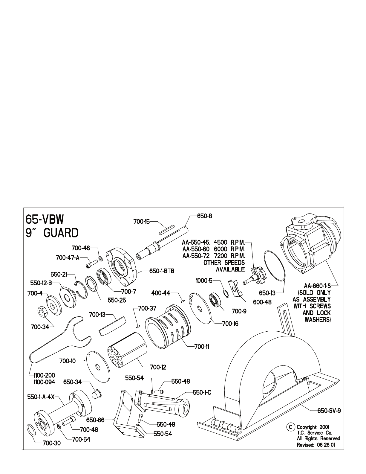
12. Slide rotor (700-12) over spindle and key. Insert four blades (700-13).
13. Place cylinder (700-11) over rotor with long dowel pin downward. Dowel pin goes through hole in
front endplate and front bearing support.
14. Place rear endplate (700-16) over cylinder. Locate the short dowel pin of the cylinder in the small
hole of rear endplate.
16. Press bearing (700-9) into rear endplate with bearing driver (1100-808).
17. Install lock ring (1000-5) onto spindle with use of snap ring pliers. (There is no groove.)
18. Prior to reassemble inspect governor for gouges, nicks or dents. Oil the governor and inside of
motor. Screw governor (AA-550-XX) into end of spindle and tighten with a wrench. (left hand thread).
19. Assemble spade handle if this was inspected or repaired.
20. Install spade and dead handles to case (660-1-S).
21. Secure tool in a vise with motor axis in horizontal position. Clap onto thespade handle.
22. Place gasket (650-13) in rear face of case.
23. Slide the motor assembly into case. The motor assembly must be kept straight to install into the
case easily. Try to maintain alignment as best as possible.
24. Line up guard with motor holes. Install 3 bolts (700-47A) and lock washers (700-46). Tighten bolts
down until snug then back off 1/2 turn.
25. Connect tool to air supply and apply air in several short bursts.
26. Now run tool and tighten down bolts evenly. (Alternating from corner to corner.)
27. Check RPM with a reliable tachometer. Tool must run at or below speed stamped on the
tool. Reinstall all flanges, accessories, and safety devices.
Table of contents


