Top WA100 User manual

Thank you for choosing TOP VME .
WA100
Remote Control Box
User Guide


Contents
1. Introduction……………………………………………………………………………………… 1
1-1. Overview……………………………………………………………………………………………… 1
1-2. Features ……………………………………………………………………………………………… 1
2. Specification …………………………………………………………………………………… 2
2-1. General………………………………………………………………………………………………… 2
2-2. Electronic …………………………………………………………………………………………… 2
2-3. Machine ……………………………………………………………………………………………… 2
3. Packing List ……………………………………………………………………………………… 2
4. Dimension………………………………………………………………………………………… 3
5. Installation ……………………………………………………………………………………… 4
5-1. Harness Application …………………………………………………………………………… 4
5-2. Hardware Application ………………………………………………………………………… 17
6. Instructions ……………………………………………………………………………………… 18
6-1. Installation Notes………………………………………………………………………………… 18
6-2. WIFI search mode ……………………………………………………………………………… 18
6-2-1. IOS Users……………………………………………………………………………………… 18
6-2-2. Android users ……………………………………………………………………………… 19
6-3. Device activate mode ………………………………………………………………………… 21
6-4. Normal mode ……………………………………………………………………………………… 23
6-5. Instruction information ……………………………………………………………………… 25
6-5-1. Disable device……………………………………………………………………………… 25
6-5-2. Key in …………………………………………………………………………………………… 27
6-5-3. key Out………………………………………………………………………………………… 28
6-5-4. Free play ……………………………………………………………………………………… 30
6-5-5. Clean current records ………………………………………………………………… 32
6.Troubleshooting………………………………………………………………………………… 34

1
WA100
1. Introduction
1-1. Overview
This product is connected between the coin selector and the vending
machine. It’s easy to install instead of modifying system and program ,
the remote control box has some function which can recode all bargain,
paying by app of phone, and adjust point from machine include claw
machinemachine, washing machine, dryer, electric massage chair , parking
payment machine, vending machine, etc.
1-2. Features
• Control remotely using your smart phone or PC.
• Easy setup with any smart phone.
• Adaptable to different machines
• Help you keep a close monitor on your income.
• 100kb~150kb transmission a day.

2
Remote control box
2. Specification
2-1. General
transmit and
receiving rate 99.99%
Data transmission 100~150 KB/Day
Response time 1.5~2 秒
Interface WIFI / PLUSE / RS232
Installation Provide WIFI space
2-2. Electronic
Power Source 12V DC ± 10%
Power
Consumption
Standby: 0.1~0.17 A
Operration Current : 0.25A
Maximum : 0.50A
Temperature
Range
Operating Temperature: 0° C~60° C
Storage Temperature: -10° C~80° C
Humidity: 20%~70% RH
(no condensation)
2-3. Machine
Weight 86±10 g
Outline
Dimension 82 x 82 x 21 mm
WIFI bandwidth 2400MHz~2483.5MHz
3. Packing List
Main WA100 Remote control box
Accessories
User Guide x1
Antenna x1
Harness x1

3
WA100
4. Dimension
Unit : mm [ inch ]
82.2 3.24
82.2 3.24
7.2
0.28
89.4 3.52
21
0.83

4
Remote control box
5. Installation
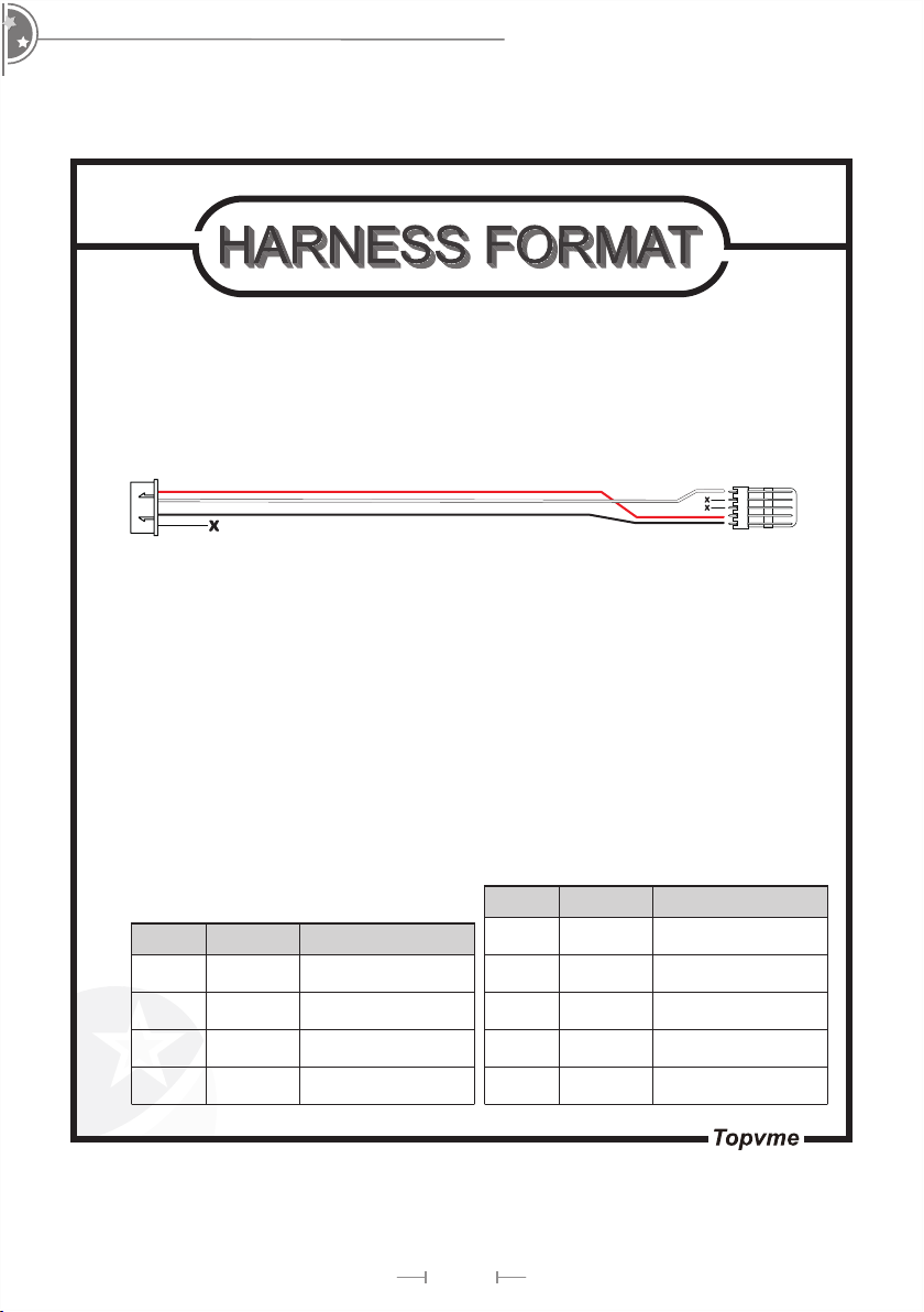
5-1. Harness Application
Interface Voltage Usage Harness NO. Page
PULSE 12V DC
Sensor 2WIR-WIFI001(Purchase) 5
Sensor 2WIR-WIFI002(Purchase) 6
Power and singal out 2WIR-WIFI003(Purchase) 7
Coin acceptor 2WIR-WIFI004(Purchase) 8
Coin acceptor 2WIR-WIFI005(Taiwan) 9
Coin acceptor 2WIR-WIFI006(Foreign) 10
Counter 2WIR-WIFI007(Purchase) 11
Power and singal out 2WIR-WIFI008(Purchase) 12
Bill acceptor 2WIR-WIFI009(Purchase) 13
Bill acceptor 2WIR-WIFI010(Purchase) 14
Power and singal out 2WIR-WIFI011(Purchase) 15
Coin selector 2WIR-WIFI012(Purchase) 16
NOTE : Software download
Please refer to the G-BOX Operation manual for a guide step by step how
to download or update using the G-Box programmer. You can obtain it
Refund coin/Counter/Sensor
(2WIR-WIFI001/2WIR-WIFI002/
2WIR-WIFI007)
TX/RX
Download
Bill Acceptor
(2WIR-WIFI009/ 2WIR-WIFI010)
Coin Acceptor
(2WIR-WIFI004/ 2WIR-WIFI005/
2WIR-WIFI006/2WIR-WIFI012)
Power and signal output
(2WIR-WIFI003/2WIR-WIFI008/
2WIR-WIFI0011)

5
WA100
2WIR-WIFI001
22 AWG
PIN 1
PIN 1
PIN 1
B
A
PIN NO COLOR PIN DEFINE
PIN1 YELLOW METER OUT
PIN2 PURPLE METER IN
PIN3 RED 12V DC
PIN4 BLACK GND
PIN5 X X
B
A
PIN NO COLOR PIN DEFINE
PIN1 X X
PIN2 YELLOW SIGNAL OUT
PIN3 X X
PIN NO COLOR PIN DEFINE
PIN1 RED 12V DC
PIN2 PURPLE SIGNAL IN
PIN3 BLACK GND
Connect with senser
Connect with main board
Connect with JP3

6
Remote control box
2WIR-WIFI002
22 AWG
PIN 1
PIN 1
PIN 1
B
B
A
A
PIN NO COLOR PIN DEFINE
PIN1 YELLOW METER OUT
PIN2 PURPLE METER IN
PIN3 RED 12V DC
PIN4 BLACK GND
PIN5 X X
PIN NO COLOR PIN DEFINE
PIN1 X X
PIN2 YELLOW SIGNAL OUT
PIN3 X X
PIN NO COLOR PIN DEFINE
PIN1 RED 12V DC
PIN2 PURPLE SIGNAL IN
PIN3 BLACK GND
Connect with JP3
Connect with senser
Connect with main board

7
WA100
22 AWG
PIN 1
1 2
5
7 8 9
2WIR-WIFI003
PIN NO COLOR PIN DEFINE
PIN1 RED 12V DC
PIN2 YELLOW COIN/BILL OUT
PIN3 ORANGE GND
PIN4 X X
PIN NO COLOR PIN DEFINE
PIN1 YELLOW COIN/BILL OUT
PIN2 X X
PIN3 X X
PIN4 X X
PIN5 RED 12V DC
PIN6 X X
PIN7 X X
PIN8 X X
PIN9 ORANGE GND
Connect with JP4

8
Remote control box
2WIR-WIFI004
22 AWG
PIN 1
PIN 1 PIN 2
PIN 1 PIN 2
A
B
PIN NO COLOR PIN DEFINE
PIN1 RED 12V DC
PIN2 PURPLE COIN IN
PIN3 BLACK GND
PIN4 X X
PIN NO COLOR PIN DEFINE
PIN1 X X
PIN2 X X
PIN3 PURPLE COIN IN
PIN4 X X
PIN5 BLACK GND
PIN6 RED 12V DC
Connect with JP5
Connect with UCA2

9
WA100
2WIR-WIFI005
22 AWG
PIN 1
PIN 1
PIN 1
PIN NO COLOR PIN DEFINE
PIN1 RED 12V DC
PIN2 WHITE COIN IN
PIN3 BLACK GND
PIN4 X X
PIN NO COLOR PIN DEFINE
PIN1 X X
PIN2 BLACK GND
PIN3 WHITE COIN IN
PIN4 RED 12V DC
Connect with coin acceptor
Connect with coin JP5

10
Remote control box
2WIR-WIFI006
22 AWG
PIN 1
PIN 1
PIN 1
PIN NO COLOR PIN DEFINE
PIN1 RED 12V DC
PIN2 WHITE COIN IN
PIN3 BLACK GND
PIN4 X X
PIN NO COLOR PIN DEFINE
PIN1 X X
PIN2 BLACK GND
PIN3 WHITE COIN IN
PIN4 RED 12V DC
Connect with coin acceptor
Connect with coin JP5

11
WA100
2WIR-WIFI007
PIN 1
PIN NO COLOR PIN DEFINE
PIN1 X X
PIN2 YELLOW METER IN
PIN3 X X
PIN4 X X
PIN5 X X
Connect with JP3
Connect with Counter

12
Remote control box
2WIR-WIFI008
22 AWG
PIN 1
PIN 1
PIN NO COLOR PIN DEFINE
PIN1 RED 12V DC
PIN2 WHITE COIN/BILL OUT
PIN3 BLACK GND
PIN4 X X
PIN NO COLOR PIN DEFINE
PIN1 RED 12V DC
PIN2 WHITE COIN/BILL OUT
PIN3 BLACK GND
PIN4 X X
Connect with JP4

13
WA100
2WIR-WIFI009
22 AWG
PIN 1
1
25
7
8
9
PIN NO COLOR PIN DEFINE
PIN1 YELLOW INHIBIT
PIN2 GREEN GND
PIN5 RED 12V DC
PIN7 BLUE 12V DC
PIN8 PURPLE BILL IN
PIN9 ORANGE GND
PIN NO COLOR PIN DEFINE
PIN1 RED 12V DC
PIN2 ORANGE GND
PIN3 YELLOW INHIBIT
PIN4 GREEN GND
PIN5 BLUE 12V DC
PIN6 PURPLE BILL IN
Connect with JP6

14
Remote control box
2WIR-WIFI010
PIN 1
PIN NO COLOR PIN DEFINE
PIN1 RED 12V DC
PIN2 ORANGE GND
PIN3 YELLOW INHIBIT
PIN4 GREEN GND
PIN5 BLUE 12V DC
PIN6 PURPLE BILL IN
PIN NO COLOR PIN DEFINE
PIN1 YELLOW INHIBIT
PIN2 GREEN GND
PIN5 RED 12V DC
PIN7 BLUE 12V DC
PIN8 PURPLE BILL IN
PIN9 ORANGE GND
Connect with JP6
15
WA100
2WIR-WIFI011
PIN NO COLOR PIN DEFINE
PIN1 BLACK GND
PIN2 RED 12V DC
PIN3 X X
PIN4 X X
PIN5 WHITE COIN/BILL OUT
PIN NO COLOR PIN DEFINE
PIN1 RED 12V DC
PIN2 WHITE COIN/BILL OUT
PIN3 BLACK GND
PIN4 X X
PIN1
PIN1
Connect with JP4

16
Remote control box
2WIR-WIFI012
PIN NO COLOR PIN DEFINE
PIN1 BLACK GND
PIN2 RED 12V DC
PIN3 X X
PIN4 X X
PIN5 WHITE COIN/BILL OUT
PIN6 X X
PIN NO COLOR PIN DEFINE
PIN1 RED 12V DC
PIN2 WHITE COIN IN
PIN3 BLACK GND
PIN4 X X
PIN1
PIN1
Connect with JP5
Connect with Coin acceptor

17
WA100
5-2. Hardware Application
Location Type Function
JP1 PORT Key in/
Key out
Provide 3 input pin and 2 output pin to
connect machine(Pulse Mode only)
JP3 PORT Hopper/Counter
Provide 1 input pin and 1 output pin to
connect Hopper or counter(Pulse Mode
only)
JP4 PORT Power/
signal output
Provide 12V power input pin and signal
output pin for coin selector and bill validator
JP5 PORT Coin selector Provide 1 input pin to connect coin selector
JP6 PORT Bill validator Provide 1 input pin and 1 output pin
to connect bill validator
J1 protocol Provide TX and RX for data
transmission
123 4
SW1
1. KEYIN IN
LED 1 LED 2
JP1
JP3
JP4
JP5JP6
2. KEYDOWN IN
3. KEYIN OUT
4. KEYDOWN OUT
5. RRE IN
6. GND
1. METER OUT
2. METER IN
3. 12V OUT
1. 12V IN
2. COIN/BILL OUT
3. GND
4. GND
5. X
4. X
SW2
SW3
SW4
12V OUT
COIN IN
GND
X
RXTX
5V
GND
12V OUT
GND
INHIBIT
GND
12V OUT
BILL IN
Function SW1 SW2 SW3 SW4
WIFI search mode ON OFF
Device activate mode OFF ON
Normal mode
JP3=Counter OFF OFF
JP3=Refund machine ON ON
JP1&JP3=NO mode OFF
JP1&JP3=NC mode ON
JP3=pulse mode OFF
JP3=hopper mode ON
Ex : If JP3 connect counter using No mode and pulse mode, all SW should be OFF abd
re-plug power.
Table of contents
Popular Remote Control manuals by other brands


EScale
EScale 2.4GHz FHSS Radio System instruction manual

Spektrum
Spektrum AR635 user guide

Philips
Philips Trilingual Front CoverArt PHBIG3 instruction manual

Rotel
Rotel RR-1070 owner's manual

Fayat Group
Fayat Group Dynapac SCREED-CONTROL Operation manual

Chamberlain
Chamberlain LiftMaster Professional 33LM owner's manual