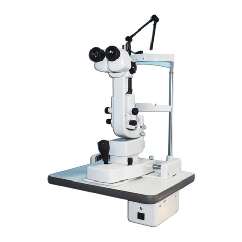
Topcon SL-6E User manual

TOPCON
TOPCON
PHOTO
SLIT
LAMP
Model
SL-6E

Congraturations
on
your
choice
of
the
TOPCON
Photo
Slit
Lamp,
Model
SL-6E,
which
is
based
on
the
time-proven
Model
SL-3E
Slit
Lamp
and,
retains
almost
all
of
its
attractive
features
and
specifications.
We
are
sure
that
it
will
also
give
you
years
of
unfailing
service,
as
well
as
being
an
attractive
instrument
for
your
office.
This
instruction
manual
covers
the
assembly,
operation,
care
and
maintenance
of
the
TOPCON
Phto
Slit
Lamp,
Model
SL-6E,
for
use
on
the
TOPCON
Adjustable
Instru-
ment
Tables,
Models
AIT-5B
and
IT-1,
and/or
TOPCON
Ophthalmic
Stands.
May
we
suggest
that
you
read
this
instruction
manual
carefully,
in
the
order
that
it
is
written,
before
you
even
touch
the
instrument.
Thoroughly
familiarize
yourself
with
the
instrument
and
you
will
be
able
to
get
the
full
benefit
of
a
superior
instrument.
IMPORTANT
READ BEFORE
TOUCHING
THE
INSTRUMENT.
1.
Please
check
the
primary
voltage
and
see
that
it
matches
that
of
your
line
current
If
the
primary
voltage
is
different,
it
can
be
adjusted
if
you
follow
instructions
on
“Checking
Voltage”.
2.
Please
check
the
plug
on
the
power
cord,
too.
If
it
is
not
suitable
for
the
receptacle,
it
can
be
exchanged
or
attached
(if
not
connected)
by
following
instructions
on
“Checking
the
Electric
Plug”.
3.
Do
not
touch
the
surfaces
of
lenses
and
mirrors
with
your
fingers
or
any
hard
object.
©
4.
Do
not
switch
the
light
on
unnecessarily.
5
.
Always
turn
the
power
switch@)
to
OFF
when
connecting
the
power
cord
to
the
line
current
or
when
exchanging
lamps.
6.
When
disconnecting
the
power
cord,
or
any
other
cord,
grip
the
connector
or
plug
firmly
and
do
not
pull
the
cord.
7.
Do
not
change
the
flash
control
switch
setting
while
the
Xenon
flash
lamp
is
dis-
charging
or
while
it
is
being
charged,
as
this
will
lead
to
troubles
in
the
power
supply
unit.
8.
Do
not
depress
the
shutter
release
buttoní)
while
the
film
winding
of
the
auto
winder.
Otherwise,
the
auto
winder
will
stop
midway.
9.
Do
not
depress
the
shutter
release
button
for
a
long
time.
10.
Do
not
take
a
picture
beyod
the
normal
exposure
number.
11.
Do
not
leave
the
instrument
in
a
location
which
is
too
dusty,
has
excessive
moisture
or
where
the
sun
will
hit
it
directly.
12.
Always
keep
the
instrument
covered
with
the
vinyl
dust
cover,
except
when
in
actual
use.
13.
Please
note
that
there
may
be
minor
differences
in
the
actual
instrument
delivered
to
you
which
are
not
covered
in
this
instruction
manual
because
such
improvements
do
not
differ
greatly
from
the
instructions
and/or
illustrations.

CONTENTS
.
FEATURES
OF
THE
TOPCON
PHOTO
SLIT
LAMP,
MODEL
SL-6E
-.................
1
.
SPECIFICATIONS
i
2
Net
5
.
ASSEMBLY
1)
Unpacking
the
Instrument
-
2)
Assembling
and
Installation.
(1)
Checking
the
plug
and
the
voltage
:
(2)
Installation
of
the
instrument
a)
Attachment
on
the
TOPCON
Adjustable
Instrument
Table-
・
b)
Attachment
on
the
Ophthalmic
Stand
-.........................
12
(3)
Attachment
of
the
Chin-rest
and
Head
Rest
Section
...
(4)
Connecting
the
cord
(5)
Checking
the
electric
plug
(6)
Setting
up
the
base
(7)
Attachment
of
the
Slit
Lamp
Arm
-
(8)
Fixing
the
Chin-rest
Pad
-----
(9)
Storage
of
accessories
.
OPERATIONS
1)
Preparations
2)
Examinations
3)
Fundus
Examinations
+++
4)
Exchanging
the
Mirrors
.
CARE
AND
MAINTENANCE
1)
Exchange
of
the
Slit
Illumination
Lamp-
2)
Exchange
of
the
Fixation
Target
Lamp
-
3)
Exchange
of
the
Fuse
4)
Adjustment
of
the
Slit
Width
Adjusting
Wheels
...
5)
Adjustment
in
the
Inclination
of
the
Illumination
n
System-
6)
Cleaning
the
Instrument
…
・

OPTIONAL
ACCESSORIES
35mm
PHOTOGRAPHIC
ATTACHMENT
SET
1)
Nomenclature
ii
2)
Assembling
and
Installation
3)
Attachment
of
the
Photographic
Unit
(1)
Attachment
the
Relay
Lens……………
(2)
Attachment
of
the
back
Ground
Illuminator
(3)
Attachment
of
the
Cord
Relay
Box::---
(4)
Attachment
of
the
diffusion
lens
-+++
(5)
Connecting
the
Xenon
Connector
Cord
(6)
Attaching
the
Xenon
Flash
Lamp…………
(7)
Attaching
the
Photographic
Attachment
(8)
Attaching
the
Camera
Body
…
(9)
Connecting
the
Cords.…………
4)
How
to
Use
a
Photographic
Attachment
(1)
Loading
Film
in
the
Camera
Body
(2)
Exposure
Counter
---..........................
(3)
Changing
of
Photographic
Magnification
(4)
Background
Illumination
111111.
(5)
Exposure
Guide
for
Photography
(6)
Photography
……
ド
ドド
ーー
(7)
Obstruction
by
Mirrors
and
Pole
(8)
Unloading
the
film
POLAROID
ATTACHMENT
Model
PA-8S
OBSERVATION
TUBE
VIDEO
ATTACHMENT
NON-CONTACT
SPECULAR
ATTACHMENT
PACHOMETER
ATTACHMENT.
12.5x
MEASURING
ΕΥΕΡΙΕΟΕ
OTHER
TROUBLES
AND
PARTS
ORDER
ーーーーー
ド
ーー
ドーー
41
1)
Before
Calling
for
Help-
...
aves
PI
2)
Spare
Parts
..
41

©
1.
FEATURES
OF
THE
TOPCON
PHOTO
SLIT
LAMP,
MODEL
SL-6E
1)
The
convenient,
one
position
control
lever
allows
the
base
to
be
guided
freely
in
fine
cross-slide
adjustment
and
vertical
movement.
2)
The
convergent
binocular
tubes
allows
easy
and
natural
stereoscopic
observation.
3)
Camera
can
be
attached
without
cluttering
microscope
area
and
without
hamper-
ing
slit
lamp
operations.
4)
Unit
construction
photographic
system
and
observation
tube
makes
attachments
and
exchanges
very
simple.
5)
Stereophotographs
can
be
taken
very
easily,
with
one
shot,
by
simply
exchanging
the
normal
photographic
attachment.
6)
Five
magnification
changes
for
observation
and
photography,
with
higher
magni-
fication
also
possible
by
interchanging
eyepieces.
7)
Photographs
are
possible,
with
simple
auto-winding
operations,
by
simply
depres-
sing
the
release
button
on
the
joystick
control
lever.
8)
Background
illumination
can
be
added
to
the
slit
lamp
photograph,
as
well
as
adjusted
in
brightness.
9)
A
beam
splitter
unit
is
inserted
between
objective
and
the
prism
housings,
with
the
observation
tube
fixed
to
either
of
the
two
beam
splitter
mounts
on
the
unit.
As
in
the
case
of
the
photographic
unit,
the
optical
path
is
partially
diverted
only
when
the
observer
uses
a
lever
for
this
purpose.
10)
Goldmann
Applanation
Tonometers
T900
and
R900
can
also
be
used.
Model
R
900
Model
T
900

©
2.
SPECIFICATIONS
Microscope
Type
Objective
Working
distance
Magnification
changing
system
Eyepieces
Total
magnifications
and
field
of
view
Interpupillary
distances
Diopter
adjustments
Slit
illumination
system
Projection
magnification
Illuminated
field
Slit
width
Slit
length
Aperture
diameters
Slit
angle
Filters
Lamp
Fixation
Targets
Annular
type
Luminous
type
Lamp
Base
Longitudinal
movement
Lateral
movement
Fine
cross-slide
adjustments
Vertical
movement
Chin-rest
vertical
range
Power
Unit:
Primary
Secondary
Power
consumption
Standard
Accessories
Hruby
lens
Hruby
lens
guide
plate
Galileo
type
direct
viewing
binocular
stereoscopic
microscope,
with
erect
image
f=
106.6mm
100.2mm
Revolver
drum,
with
5
magnification
changes
12.5%
6X
(33mm¢),
10X
(22.5mm¢),
16X
(14mm¢),
25x
(8.8mmg)
and
40x
(5.5mm¢)
55mm
to
75mm
+3D
to
—5D
2/3X
Continuously
variable
from
O
to
9mmifield
of
view
is
round
at
9mm)
Continuously
variable
from
1mm
to
8mm
7
stops,
9, 8, 5,
3,
2,
1
and
0.2mm¢
Consecutively
variable
from
vertical
to
horizon-
tal:
horizontal
scanning
through
180°
from
zero;
slit
projection
can
be
inclined
to
5°,
10°,
15°
and
20°
Blue,
red-free,
13%
neutral
density
and
heat
ab-
sorbing
filters
built
in.
6V
27W
precentered
tungsten
filament
lamp;
brightness
adjustable
in
3
stages
Adjustable
from
—15D
to
+10D
Interchangeable
with
annular
target
6V
0.2A
80mm
100mm
12mm
in
both
longitudinal
and
lateral
directions
30mm
80mm
50/60
Hz;
AC
100V,
120V,
220V
and
240V;
adjustable
with
built-in
voltage
selector
AC
4.5V,
6.3V
and
7.5V;
adjustable
with
rotary
switch
45VA
—58.7D,
for
examinations
of
the
vitreous
body
and
fundus
Also
doubles
as
mount
for
Goldmann
Applana-
tion
Tonometer
T900.
(Hruby
lens
and
Hruby
lens
guide
plate
are
are
optional
accessories
for
certain
markets.)
2

Dimensions
&
Weight
Table
surface
Height
from
table
surface
Weight
(Body)
Optional
Accessories
560mm
x
350mm
740mm
21
kgs.
35mm
Photographic
attachment
set
for
normal
photography
Optical
axis
for
photography
Photographic
magnifications
Camera
body
Flash
illumination
Power
unit
Primary
Secondary
Power
consumption
Stereo
Photographic
attachment
Photographic
magnification
Observation
Tube
Type
Adjustable
Instrument
Table
Right
side
0.9x,
1.4x,
2.2x
,
3.5X
Exclusive
TOPCON
camera
with
Auto
Winder
280V
200WS
Xenon
fiash
lamp;
also
used
for
background
illumination
2
stages
brightness
ad-
justment
and
black-out
50/60
Hz;
AC
100V,
120V,
200V,
220V
and
240V;
adjustable
with
voltage
selector
Adjustable
in
5
stages
20,
40,
80,
160
and
200WS
300
VA
0.6x,
1x,
1.6x,
2.6X
Beam
splitter
mount
type,
with
optical
path
moved
in/out
as
required;
can
be
attached
on
either
of
two
attachment
mounts
of
beam
split-
ter
unit;
built-in
image
rotator
prism
There
are
two
types
of
adjustable
instrument
tables
available.
Model
AIT-5B
A
motorized
table
which
provides
exceptionally
stable
support
for
most
in-
strumentation.
The
table
can
raise
or
lower
instruments
weighing
up
to
80kgs
throughout
the
full
250mm
range.
The
minimum
table
height
is
669mm
while
the
maximum
height
is
919mm.
Activation
of
the
motor
is
through
a
switch
located
in
the
center
of
the
support
pedastal.
Four
large
diameter
rubber
casters,
two
with
locking
devices,
allow
for
easy
positioning.
A
convenience
electrical
outlet
is
located
at
the
base.
Model
IT-1
This
manually
adjustable
instrument
table
provides
a
sturdy
and
stable
sup-
port
for
instruments
weighing
up
to
27kgs.
The
verticle
adjustment
range
of
250mm
is
from
686mm
to
936mm.
Four
large
diameter
rubber
casters
provide
for
smooth
movement,
with
two
of
the
casters
having
locks
to
prevent
any
movement
during
diagnostic
procedures.

IT-1
Fig.
3
AIT-5B
Fig.
4
Ophthalmic
Stands
There
are
several
types
ophthalmic
stands
available
for
use
with
SL-6E,
which
all
have
an
electrical
outlet
for
utilization
by
the
instrument.
The
optional
accessory
and
equipment
noted
above
are
available
against
special
orders
and
extra
cost.
They
are
all
recommended
for
optimum
performance
of
the
TOPCON
Photo
Slit
Lamp.
At
the
same
time,
it
should
be
noted
that
there
may
be
changes
in
these
accessory
and/or
equipment
in
the
future.
Subject
to
changes
in
designs
and/or
specifications,
without
advance
notice.

3.
NOMENCLATURE


(1)
Table
(2)
Accessory
drawer
(3)
Power
unit
(4)
Power
switch
©
Illumination
control
switch
(6)
Gliding
plate
©
Rail
Rail
cover
(©
Base
fixing
screw
(0
Control
lever
(7
Release
button
(3
Connected
cord
(4
Microscope
arm
fixing
knob
45
Slit
lamp
arm
fixing
knob
(©
Protractor
scale
(7)
Click-stop
roller
(8,
Hruby
lens
guide
plate
09
Microscope
arm
©
Exclusive
table
for
use
on
the
TOPCON
Ad-
justable
Instrument
Table,
Model
AIT-5B
or
Model
IT-1.
Has
gliding
plate
and
twin
toothed
rails,
for
providing
the
cross-slide
base
section
with
free
moving
capability
for
locating
the
in-
strument.
(Replaced
with
smaller
exclusive
table
for
use
on
TOPCON
Ophthalmic
Stand
but
with
same
gliding
plate
and
toothed
rails.)
Provided
on
the
above
table
only
for
storage
of
standard
accessories,
such
as
eyepiece
lenses,
mirrors,
test
rods,
etc.
(Not
available
on
table
for
use
with
Ophthalmic
Stand.)
Available
on
both
types
of
tables
with
built-in
step-down
transformer
for
use
with
AC
100,
120,
220,
and
240
volts,
as
set
with
voltage.
selecter
42.
Main
switch
for
the
power
unit.
Has
three
settings
or
—L(4.5)—N(6.3)—H(7.5).
Used
for
controlling
secondary
voltage
to
the
slit
lamp
and,
consequently,
brightness
of
the
slit
image.
Provides
the
cross-slide
base
with
free
move-
ment
in
all
directions
and,
therefore,
must
be
kept clean
and
smooth.
Toothed
rails
are
provided
for
accepting
the
twin
rollers
of
the
base,
and
provide
longitudinal
movement.
Snap-in
covers
are
provided
for
both
toothed
rails
7).
Used
to
fix
the
base
from
moving.
Loosened
by
counter-clockwise
revolution
and
tightened
by
clockwise
revolution.
The
tip
of
this
lever
is
tilted
slightly,
in
the
required
direction,
for
making
fine
adjust-
‘ments
in
the
position.
Also,
used
to
elevate
or
lower
the
instrument
by
rotating
the
lever.
For
releasing
shutter
of
the
camera
body.
Between
the
base
and
the
microscope.
Locks
microscope
arm(9
from
rotating;
when
loosend,
permits
rotation
of
the
microscope
arm.
Couples
slit
lamp
arm
and
microscope
arm(9)
when
tightend;
slit
lamp
arm
rotates
alone,
when
loosened.
Scale
is
used
for
reading
the
angle
between
the
microscope
arm(9
and
the
slit
lamp
arm.
The
click-stop
roller
indicates
when
the
slit
lamp
arm
is
at
O°,
or
central
position,
or
10°
to
the
right
or
left
of
the
central
position.
Used
for
coupling
Hruby
lens,
when
placed
in
the
socket
of
the
rotation
axis
of
the
microscope
and
slit
lamp
arms.
Also
for
use
as
tonometer
mount
in
coupling
Goldmann
Applanation
Tono-
meter
Model
T900.
Can
be
rotated
freely
or
in
coupled
movement
7

@
Chin-rest
adjusting
wheel
@)
Chin-rest
@)
Magnification
changer
handle
@3)
12.5
eyepiece
lenses
4
Fixing
ring
@)
Beam
splitter
lever
@ÿ
Tonometer
mount
@
Mirror
Slit
width
adjusting
wheels
@9
Slit
inclination
stopper
(80)
Centering
knob
6)
Hruby
lens
attachment
mount
62
Hruby
lens
63
Level
marker
64
Annular
fixation
target
69
Slit
diaphragm
plate
handle.
@6
Filter
lever
with
the
slit
lamp
arm.
Used
for
adjusting
the
height
of
chin-rest@).
Supports
the
patinet's
chin
and
can
be
adjusted
up
or
down,
to
locate
the
patient's
eyes
at
the
correct
height.
Rotated
for
making
five
changes
in
magnifi-
cation.
Sleeve
insert
type
eyepiece
lenses.
The
ring
is
revolved,
the
prism
housing
can
be
detached.
After
that,
the
align
the
pin
of
the
beam
spliter
Unit
to
its
notch
For
photography,
the
lever
must
be
pushed
IN.
For
use
of
Goldmann
Applanation
Tonometer
Model
R900.
Reflection
mirror
for
the
slit
illumination
system.
Long
mirror
can
be
exchanged
for
the
short
mirror⑥,
in
cases
where
the
long
mirror
ob-
structs
the
microscope's
lines
of
sight.
Either
wheel
can
be
used
for
adjusting
the
width
of
the
slit
illumination
from
O
to
9mm,
by
rotating
in
either
direction.
Stopper
plate
for
5°
intervals
in
the
inclination
of
the
slit
illumination
system
up
to
20°.
The
knob
is
loosened,
by
counter-clockwise
revolution,
which
will
permit
movement
of
the
slit
image
away
from
the
center
of
the
field
of
view.
A
sliding
mount
used
for
attachment
of
the
Hruby
lens.
Can
be
located
over
the
guide
plate
for
use
in
front
of
either
eye.
Used
on
the
Hruby
lens
attachment
mount6)
coupled
to
the
guide
plate,
for
examinations
of
the
vitreons
body
and
the
fundus.
Used
to
indicate
the
proper
height
for
the
pa-
tient's
eyes,
as
adjusted
by
raising
or
lowering
the
chin-rest.
Adjustment
from
—15
to
+10
diopters,
to
suit
patient's
refractive
power.
Rotation
around
the
axis
of
the
handle
produces
7
aperture
changes
of
9, 8,
5,
3,
2,
1
and
0.2mm,
which
is
then
followed
by
infinitely
vari-
able
changes
in
the
slit
length
from
1
to
8mm,
as
indicated
on
the
slit
diameter/length
scale@7.
There
are
also
click-stops
at
the
1
to
8mm
set-
tings,
in
the
latter
case.
Swinging
the
same
han-
dle
in
the
horizontal
plane
will
also
rotate
the
slit
image
consecutively
from
the
vertical
to
the
horizontal
in
both
directions.
Used
for
insertion
of
4
filters
or
heat
absorbing,
13%
neutral
density,
red
free
and
blue,
as
well
as
an
open
aperture
at
the
beginning.
The
filters
and
open
aperture
are
indicated
by
symbols
or
an
open
circle,
a
grey
colored,
a
cir-
cular,
a
green-colored
round
and
a
blue-colored
indexes.
8

@
Slit
diameter
/length
scale.
Shows
7
click
stop
apertures
and
the
infinitely
variable
slit
length
produced
with
the
slit
dia-
phragm
plate
handle.
68
Setting
pin
for
background
illumination
69
Lamphouse
cover
Head
rest
@
Fuse
holder
@
Voltage
selector
Power
cord
Cord
holder
Head
rest
attachment
plate
When
the
background
illumination
hit
the
pa-
tient's
fore
head,
it
is
stored
on
the
pin.
Encloses
the
slit
illumination
lamp.
Can
be
adjusted
for
primary
voltages
of
AC
100, 120,
220,
or
240V.
Fig.
7

@
Slit
illumination
lamp
Test
rods
@
Chin-rest
pads
60
Luminous
fixation
target
6)
Short
mirror
62
Fuse
Exposed
when
lamphouse
cover@9)
is
detached.
For
use
in
adjusting
the
eyepiece
lenses
to
the
user's
eyesight.
Used
on
the
chin-rest
for
providing
a
clean,
hygenic
surface
for
each
patient.
Used
in
place
of
the
annular
fixation
target.
Used
in
place
of
the
long
mirror
when
the
lines
of
sight
of
the
microscope
is
obstructed.
Glass-shielded
fuse.
Fig.
8
10

4.
ASSEMBLY
1)
Unpacking
the
instrument
SL-6E
is
disassembled
and
packed
carefully
for
export
shipments.
Normally,
the
instrument(Body
and
standard
accessories)
is
packed
in
one
styrol-
foam
box, with
cut-outs
for
inserting
individual
parts.
(Remarks:
Optional
accessories
are
packed
separately)
Table,
with
power
unit
and
accessory
drawer
1
each
®
Convergent
binocular
tubes
1
each
©
Base
section
1
each
@
Illumination
section
and
lamps
1
each
(©
Chin-rest
and
head
rest
section
1
each
Rail
cover
1
pair
(8
Hruby
lens
guide
plate.
1
each
@
Long
mirror(spare)
1
each
@2
Hruby
lens
1
each
@
Power
cord
1
each
@
Slit
illumination
lamp
(spare)
2
each
@
Test rods
@
Chin-rest
pads
60
Luminous
fixation
target
6)
Short
mirror
each
pack
each
each
each
each
each
otal
3
pes.
(©
Vinyl
dust
cover
@
Cleaning
brush
®
Instruction
manual
1
1
1
1
6
Fuse
(spare)
1
each
1
1
1
@
Screw
drivers
and
a
Spanner
t

e
2)
Assembling
and
Instalation
(1)
Checking
the
plug
and
the
voltage
Before
actually
assembling
the
instrument,
first
check
the
primary
voltage
of
the
instrument
and
the
electric
plug
connected
to
the
power
cord.
Next,
check
the
voltage
set
with
the
voltage
selector@d.
(2)
Installation
of
the
Instrument
The
Slit
Lamp
can
be
used
on
top
of
the
TOPCON
Adjustable
Instrument
Table,
or
on
the
lower
instrument
arm
of
the
TOPCON
Ophthalmic
Stand,
as
well
as
being
used
on
other
similiar
equipment.
As
noted,
however,
Model
SL-6E
is
available
with
two
types
of
table
or
an
exclusive
table@)
for
use
on
the
adjustable
instrument
table,
which
is
larger
and
has
a
power
unit
and
an
accessory
drawer,
and
an
exclusive
table
for
use
on
the
ophthalmic
stand,
which
is
smaller,
has
a
power
unit
only
and
also
a
pro-
trusion
or
short
pole
for
fitting
the
socket
on
the
lower
instrument
arm.
a)
Attachment
on
the
TOPCON
Adjustable
Instrument
Table
.
Mount
the
table
of
the
instrument
on
the
adjustable
instrument
table
using
four
mounting
bolts
M8
X
20mm
with
spring
washers.
Slightly
raise
the
AIT-5B
whose
vertical
movement
is
set
to
the
lower
limit
to be
deterrent
to
bolt
insertion.
Note:
Check
the
input
voltage and
—
fuses
before
moving
the
adjustable
instrument
table.
Fig.
12
Allow
the
side
of
the
power
supply
i
panel
of
&
and
the
vertical
operating
side
of
the
adjustable
instrument
table
to
face
in
the
same
direction,
have
the
mounting
holes
aligned,
place
©
on the
adjustable
instrument
table,
then
tighten
the
bolts
with
a
spanner.
b
Attachment
on
the
Ophthalmic
Stand
Remove
the
tape
which
holds
the
plastic
washer
on the
shaft
under
the
stand.
With
the
plastic
washer
attached,
insert
the
shaft
into
the
hole
of
the
ophthalmic
stand
arm.
Note:
When
using
the
table,
ine
oph-
thalmic
stand
is
provided
with
a
power
supply
to
render
the
unit
right-handed
for
the
inspector.
If
the
ophthalmic
stand
is
installed
left-handed,
it
may
cause
the
power
supply
to
come
in
contact
with
the
arm,
so
that
remove
the
power
sup-
ply
(by
removing
4
wood
screws)
and
mount
it
right-handed.
12

(3)
Attachment
of
the
Chin-rest
and
Head
Rest
Section
Unscrew,
with
the
screwdriver
four(4)
attachment
screws
on the
chin-rest
attachment
mounted
below
the table.
Place
the
cord
in
the
gap
between
the
chin-rest
attachment
plate
and
the
table
and
confirm
the
cords
are
not
caught
between
plate
and
chin-rest
section,
fix
the
chin
rest
section
with
four
screws.
(4)
Connecting
the
cord
Connect
the
cords
of
chin
rest
section.
and
power
cord
to
the
power
supply.
Remove
the
cord
holders
4
.
Pass the
cord
through
the
cord
holder
44
fitted
to
the
lower
face
of
table
and
fix
it.
Fig.
16
(5)
Checking
the
electric plug
Check
whether
the
electric
plug
connected
to
the
power
cord
matches
that
of
13

(6
the
room
receptacle.
If
not,
exchange
it
for
a
suitable
one.
On
the
other hand,
the
electric
plug
may
not
be
connected
at
all,
because
of
specialiazed
requirements
in
your
region,
in
which
case,
connect
a
suitable
plug.
There
are
three
electric
wires
in
the
power
cord.
Among
three
wires,
the
green/yellow(or
green)
wire
should
be
connected
to
the
grounding
terminal.
Setting
up
the
Base
Simply
place
the
base
section
on
top
of
the
tablet),
with
the
outrigger
rollers
aligned
on
top
of
the
toothed
rails
(7).
Next,
insert
the
rail
covers(8)
in
place,
over
the
rails.
Insert
the
flange,
on
the
base
of
the
cover,
between
the
slight
opening
which
exists
between
the
rail
and
the
surface
of
the
table.
(See
Fig.
17)
Tighten
the
base
fixing
screw(9)
to
facilitate
further
work.
.
Fig.
17
(7)
Attachment
of
the
Slit
Lamp
Arm
Loosen
the
microscope
arm
fixing
knob
screw
and
rotate
the
microscope
arm
19
60º
or
90º
to
the
right
or
left,
from
its
central
position,
which
will
be
more
convenient
for
attaching
the
slit
lamp
arm.
Next,
loosen
the
setscrew
protruding
on
the
outside
of
the
slit
lamp
arm's
at-
tachment
socket
so
that
it
no
longer
protrudes
inside
the
socket.
Finally,
lower
the
slit
lamp
arm
carefully
into
position,
as
in
Fig.
18,
while,
at
the
same
time,
lining
up
two
red
dots.
When
properly
aligned,
screw
:n
the
setscrew
tightly,
as
in
Fig.
19,
so
that
the
slit
lamp
arm
cannot
be
deiached.
Fig.
18
Fig.
19
Connect
the
cord
which
is
found
on
the
chin-rest
with
the
Lamphouse
coverá)
14

(8)
Fixing
the
Chin-Rest
Pads
Pull
out the
pad
fixing
pins,
on
both
sides
of
the
chin-rest,
by,
first,
pushing
them
up
from
below.
Next,
take
a
suitable
quantity
of
the
pads
and
place
them
on
top
of
the
chin-rest.
Finally,
fix
them
in
place,
by
passing
the
two
pad
fixing
pins
through
the
openings
of
the
pads.
(See
Fig.
20)
Tear
off
one
tissue
pad
each,
after
examining
a
patient,
which
will
place
a
new
one
in
place
for
the
next
patient.
Fig.
20
(9)
Storage
of
Accessories
Store
the
standard
accessories
supplied
with
the
instrument
in
the
accessory
drawer(2),
as
shown
in
Fig.
21,
in
the
case
of
table).
When
the
Slit
Lamp
is
used
on
the
lower
instrument
arm
of
the
ophthalmic
stand,
there
is
no
accessory
drawer
and
the
standard
accessories
should
be
stored
in
the
box
supplied
for
this
purpose.
(See
Fig.
22)
Fig.
21
Fig.
22
15

e
(5.
OPERATIONS
1)
Preparations
(1)
(2)
(3)
Use
the
instrument
in
a
dark
room
Insert
the
plug
of
the
power
cord@3
into
the
nearest
convenient
room
receptacle
Confirm
that
the
grounding
was
completed
Set
the
beam
splitter
lever
to
“OUT”.
(VIN"
is
used
in
case
of
photography)
Insert
the
test
rods4ğ
into
the
opening
on
top
of
the
post
around
which
the
microscope
arm
and
slit
lamp
arm
rotate
Switch
on
the
power
switch@)
and
check
whether
the
slit
illumination
lamp@
and
the
fixation
target
lamp
are
illuminated
or
not.
Project
a
suitable
slit
image
on
the
test
rod@8).
Revolve
the
slit
width
adjusting
wheel@
to
adjust
the
width
of
the
slit
and
revolve
the
milled
knob
of
the
slit
diaphragm
plate
handle65,
around
the
axis
of
the
handle,
to
change
the
length
of
the
slit.
The
cross-scales
seen
in
the
field
of
view
of
one
of
the
eyepieces@
is
used
for
adjusting
the
eyepieces
to
the
user's
eyesight.
(The
cross-scales
can
be
placed
in
the
field
of
view
of
either
eyepiece,
as
found
suitable.)
The
eyepiece,
in
which
the
cross-scales
can
be
seen,
should
be
used
for
making
dioptric
adjustments
for
both
eyes
of
the
operator,
with
the
required
dioptric
power
for
the
other
eye
transferred
to
the
other
eyepiece.
Dioptric
adjustments
are
made
by,
first,
drawing
out
the
eyepiece
lens
fully,
by
re-
volving
the
eyepiece
adjustment
ring.
This
will
result
in
the
cross-scales
appearing
blurred
and
indistinct.
Next,
slowly
turn
the
eyepiece
adjustment
ring
in,
until
the
cross-
scales
are
seen
clearly
and
distinctly
and
then
stop.
If
the
eyepiece
adjustment
ring
is
revolved
beyond
the
point
of
clear
focus,
then
draw
the
eyepiece
lens
out
completely
once
and
repeat
the
adjustment.
The
eyepiece
adjustment
ring
has
a
dioptric
scale
engraved
on
it,
with
each
scale
division
Fig.
23
representing
one
diopter.
If
you
can
remem-
ber the
dioptric
adjustments
for
both
eye-
pieces,
it
will
only
be
necessary
to
set
the
adjustment
rings
to
the
required
settings
on
the
scales
of
the
eyepieces,
without
going
through
the
above
adjustments
each
time.
(Fig.
23)
Adjust
the
pupillary
distance.
The
pupillary
distance
between
the
binoc-
ular
eyepieces
is
adjusted
by
simply
rotating
the
prism
housings
outwards
to
increase
the
distance
and
inwards
to
decrease
the
dis-
tance.
Fig.
24
The
adjustment
range
is
from
55mm
to
75
mm,
(See
Fig.
24)
When
the
pupillary
distance
is
adjusted
16
Other Topcon Medical Equipment manuals
Topcon
Topcon DC-4 User manual

Topcon
Topcon CT-1P User manual

Topcon
Topcon SL-D7 User manual

Topcon
Topcon KR-1 User manual

Topcon
Topcon CV-50000 User manual

Topcon
Topcon KB-50 User manual

Topcon
Topcon RM-8900 User manual

Topcon
Topcon SL-D4 User manual

Topcon
Topcon 3D OCT-1 User manual

Topcon
Topcon GTS-3B User manual

Topcon
Topcon SL-1E User manual

Topcon
Topcon 3D OCT-1 User manual

Topcon
Topcon DRI OCT-1 Triton User manual

Topcon
Topcon OM-4 User manual

Topcon
Topcon MC-4S User manual

Topcon
Topcon 3D OCT-1 User manual

Topcon
Topcon SP-1P Service manual
Topcon
Topcon SL-D701 User manual

Topcon
Topcon TRK-1P User manual
Topcon
Topcon TRC-NW8Fplus Assembly instructions