Sign IM Nail and Interlocking Screw System User manual

Technique Manual
of
SIGN IM Nail & Interlocking Screw System
Insertion & Extraction Guide
www.sign-post.org
Revision # TM-2011.07.01

2
Dear SIGN Partner:
SIGN implants are made from stainless steel that satisfies ASTM implant-grade material
specifications acceptable to the U.S. FDA. Our orthopaedic hardware manufacturing operation is
being conducted in accordance with national good manufacturing practices and quality assurance
standards. The SIGN IM Nail is a legally distributed device in the United States.
Features of the SIGN nail
Interlocking can be accomplished without C-arm
Stainless steel-less adherence of biofilm than titanium alloy, easier to remove stainless steel
nail than titanium
Solid-stronger with less bending than hollow nails. Less infection as less area for biofilm to
adhere
Slots-allow for compression and distraction of fracture site to accelerate healing
9º bend in proximal nail
1-1/2º bend in distal end for easier insertion
The SIGN Surgical Database was implemented in August 2003 to record SIGN surgeries. We request
that each SIGN surgery be recorded in the database, photos of pre and post op x-rays are requested to
accompany each report. Follow-up x-rays are appreciated. We will answer your questions or
comments in the comment section.
We value your comments on any aspect of SIGN. It is a team effort. We can be reached by e-mail,
fax, or telephone.
The SIGN technique manual is updated frequently. For updates please visit our website at www.sign-
post.org and click on manual, username sign and password 03signtech. Please read this manual
several times before your first SIGN surgery. Refer to it for each step in the OR as you do your first
surgeries.
Sincerely,
Lewis G. Zirkle, M.D.
SIGN Founder & President
451 Hills Street, Suite B, Richland, WA 99354 USA
Phone: (509) 371-1107; Fax: (509) 371-1316
E-mail: signcom@sign-post.org
Web site: www.sign-post.org
Lewis G. Zirkle, M.D.
President & Founder

3
Index
Page Subject
6 Indication for SIGN Nails
7 Operating room equipment
8 SIGN instruments
10 SIGN Nails
11 Technique for all fractures in all locations
21 Extractor/Compressor
23 Tibia
26 Retrograde approach to femur
30 Antegrade approach to femur
34 Fin nail
36 Humerus
38 Distractor instructions
39 Removal of broken nail
39 Additional notes
41 Data collection sheets

4
FOR THE PERSONAL ATTENTION OF THE OPERATING SURGEON
SIGN STANDARD IM NAILS AND FIN NAILS
DESCRIPTION: SIGN intramedullary rods, fin nails and screws are designed to provide fixation of
tibial, femoral and humeral fractures while they heal.
INFORMATION FOR USE: The surgeon must select the type and size that best meets the patient’s
requirements for close adaptation and firm seating with adequate support.
INDICATIONS: The SIGN IM Nail is indicated for internal fixation of diaphyseal tibial fractures
and distal femur fractures including transverse fractures, oblique and spiral fractures, comminuted
fractures, fractures with bone loss, open fractures, corrective osteotomies, pathologic fractures,
pseudoarthrosis of the tibial shaft, nonunions, malunions and fractures of the proximal femur. The
SIGN Fin nail is indicated for internal fixation of stable fractures in the femur and humerus.
CONTRAINDICATIONS: Active or latent infection. Wounds should be closed and dry.
Osteoporosis, insufficient quantity or quality of bone/soft tissue. Material sensitivity. If suspected,
tests are to be performed prior to implantation. Patients who are unwilling or incapable of following
postoperative care instructions.
WARNINGS: For safe and effective use of this implant, the surgeon must be thoroughly familiar
with the implant, the method of application, instruments, and the recommended surgical technique for
this device. Device breakage or damage can occur when the implant is subjected to increased loading
associated with delayed union, nonunion, or incomplete healing. Improper insertion of the device
during implantation can increase the possibility of loosening and migration. The patient must be
cautioned, preferably in writing, about the use, limitations, and possible adverse effects of this
implant including the possibility of the device failing as a result of loose fixation and/or loosening,
stress, excessive activity, or weight bearing or load bearing, particularly if the implant experiences
increased loads due to delayed union, nonunion, or incomplete healing. The patient must be warned
that failure to follow postoperative care instructions can cause the implant and/or treatment to fail.
PRECAUTIONS: An implant shall never be reused. Previous stresses may have created
imperfections which can lead to device failure. Instruments shall be inspected for wear or damage
prior to usage. Protect implant appliances against scratching and nicking. Such stress concentrations
can lead to failure.
ADVERSE EFFECTS: Fracture of the implant due to excessive activity, prolonged loading upon
the device, incomplete healing, or excessive force exerted on the implant during insertion. Implant
migration and/or loosening. Metal sensitivity or histological or allergic reaction resulting from
implantation of a foreign material. Pain, discomfort, or abnormal sensations due to the presence of an
implant. Nerve damage resulting from surgical trauma. Necrosis of bone or bone resorption.
Necrosis of tissue or inadequate healing may occur with any fracture.
STERILITY: All Implants and Instruments are provided non-sterile. Sterilization must be
performed prior to surgery, using one of the following methods. For a gravity displacement autoclave,
set at 250ºF (121ºC) for 30 min., allow drying time of 45 min. For a prevacuum autoclave, set at
270ºF (132ºC) for 4 min., allow drying time of 30 min. or at 273ºF-279ºF (134ºC to 137ºC) for 3

5
min., allow drying time of 16 min. Please consider your equipment manufacturer’s written
instructions for the specific sterilizer and load configuration being used and current AORN standards
and recommended practices. NOTE: these parameters are for full loads using wrapped sets, rigid
containers and /or peel pouches.
STORAGE INSTRUCTIONS: Store in a cool dry place, and keep away from direct sunlight. Prior
to use, inspect product package for signs of tampering, damage, or water contamination. Use oldest
lots first.
SIGN INSTRUMENTS: SIGN instruments are reusable; however, they have a limited life span.
Prior to and after each use, the instruments must be inspected where applicable for sharpness, wear,
damage, proper cleaning, corrosion and integrity of the connecting mechanisms. Notify SIGN if they
should be replaced. Instrument breakage or damage can occur when an instrument is subjected to
excessive loads, speeds, or dense bone. Striking the cutting surfaces with other metal will cause these
surfaces to become dull.
CLEANING: SIGN instruments and accessories must be thoroughly cleaned before reuse.
Decontamination of reusable instruments should occur immediately after completion of the surgical
procedure. Excess blood or debris should be wiped off to prevent it from drying onto the surface.
Use an enzymatic-cleaning product such as Enzol.
NOTE: Even surgical instruments manufactured from high-grade stainless steel must be dried
thoroughly to prevent rust formation. All devices must be inspected for cleanliness of
surface and joints, proper function, and wear and tear prior to sterilization.
SHARPENING: The drill bits become dull if they are dinged by hitting the nail or other metal.
They should be protected during surgery, cleaning and sterilization. They are also dulled by pushing
drill bits into bone when they are not advancing. The drill bit heats up and becomes dull.

6
INDICATIONS FOR SIGN NAIL
FRACTURE TYPE
a. Closed at time of injury
Fractures that cannot be reduced or lose reduction.
b. Open-acute
Fractures that are Gustilo grade I, II, III a, debrided and closed within 24 hours of injury may
have immediate SIGN nail insertion. Sometimes this time limit is impossible, so we must
study the elapsed time between injury and surgery if antibiotics are given within 6 hours from
injury. If closure is delayed, the surgeon should determine when the SIGN nail is placed at
wound closure.
c. Open-delayed closure
Debrided and covered by skin, muscle or free flap, with no drainage, may have SIGN
nail insertion.
d. Fractures treated by external fixation
Risk of infection is increased if external fixation pins are present for over 10 days but we are
studying this as closure at 10 days may not be indicated.
e. Non-unions
PATIENT PREPARATION
Patient must have no infected areas or injuries that preclude surgery. Patient should be told about
risks, benefits of surgery and agree to insertion of SIGN nail. Please check the patient’s skin the night
before surgery. If possible, washing the patient’s leg should be done the night before. The cast may
be removed for washing.
Check list for the night before surgery
1. Any infections? Where? –Surgery should be postponed.
2. Skin of extremity washed well.
3. Range of motion of knee? –need 60°flexion to do retrograde femur approach.
4. Template X-rays to estimate size of nail, screws.
5. X-rays to be in OR.
6. Check appropriate lab work.
SURGEON PREPARATION
Read the technique manual and /or watch the technique CD. Be contemplative surgeons.
X-RAYS
X-rays should include knee and ankle on the same film to measure the nail. X-rays should be present
in OR during surgery. Look carefully for fracture comminution.
ANTIBIOTICS
Antibiotics are started 1 hour before surgery.
7
OPERATING ROOM EQUIPMENT
These materials, which are not part of the SIGN set, should be present in the operating room:
drill; chuck key; mallet; bone holding forceps; knife; forceps; clamps; cautery; suction; towel clips;
needle holders; sutures; retractors, bone reamer, curved awl and periosteal elevator.
All personnel must wear masks, hats, and cover as much skin as possible. Bacteria spread to the
wound on skin cells from people in the operating room. Traffic in the OR should be minimal.
(SIGN) EQUIPMENT NECESSARY FOR USE OF SIGN NAIL:
L-handle
Locking Bolt - (2) one is extra
Target Arm (Long Proximal Target Arm, Distal Target Arm)
Short Target Arm (for use with nails shorter than 280mm)
Distal Cap Screws - (4) two are extra
Shoulder Cap Screw - (2) one is extra
Combination Hex Wrench - (2) one end fits the Locking Bolt, Shoulder Cap Screw and Distal
Cap Screws. The other end fits the interlocking screws.
Cannula
Alignment Pin - (2)
Drill Guides - (2) (one large for large drill bits) (one small for small drill bits)
Drill Bits
oLarge (2) (6.3mm) for near cortex
oSmall (2) (3.5mm) for both near & far cortex
Screw Caddy and SIGN Interlocking screw assortment
SIGN IM nail assortment
Hex Driver (3.5mm)
Extractor/Compressor Set
oExtractor Rod Connector
oExtractor-Compressor Rod
oSlap Hammer Weight
Slot Finders: Cannulated, Solid and Curved (one of each)
11mm Wrench
Tissue Protector - (2) one is extra (these are reusable)
Depth Gauge
Step Drill
Screw Hole Broach
Care of SIGN Equipment:
It is essential that the equipment be well maintained as described on Page 4. Sometimes during the
surgery the cannula and drill bits become bloody. They should be washed off before the next
interlock, as they may stick due to the close fit. This also applies to the threads of caps screws.
NOTE: Please protect the drill bits, reamers and step drill from striking metal objects during
surgery and cleaning.
Be sure an assortment
of sizes are sterilized.

8
SIGN Instruments

9
10
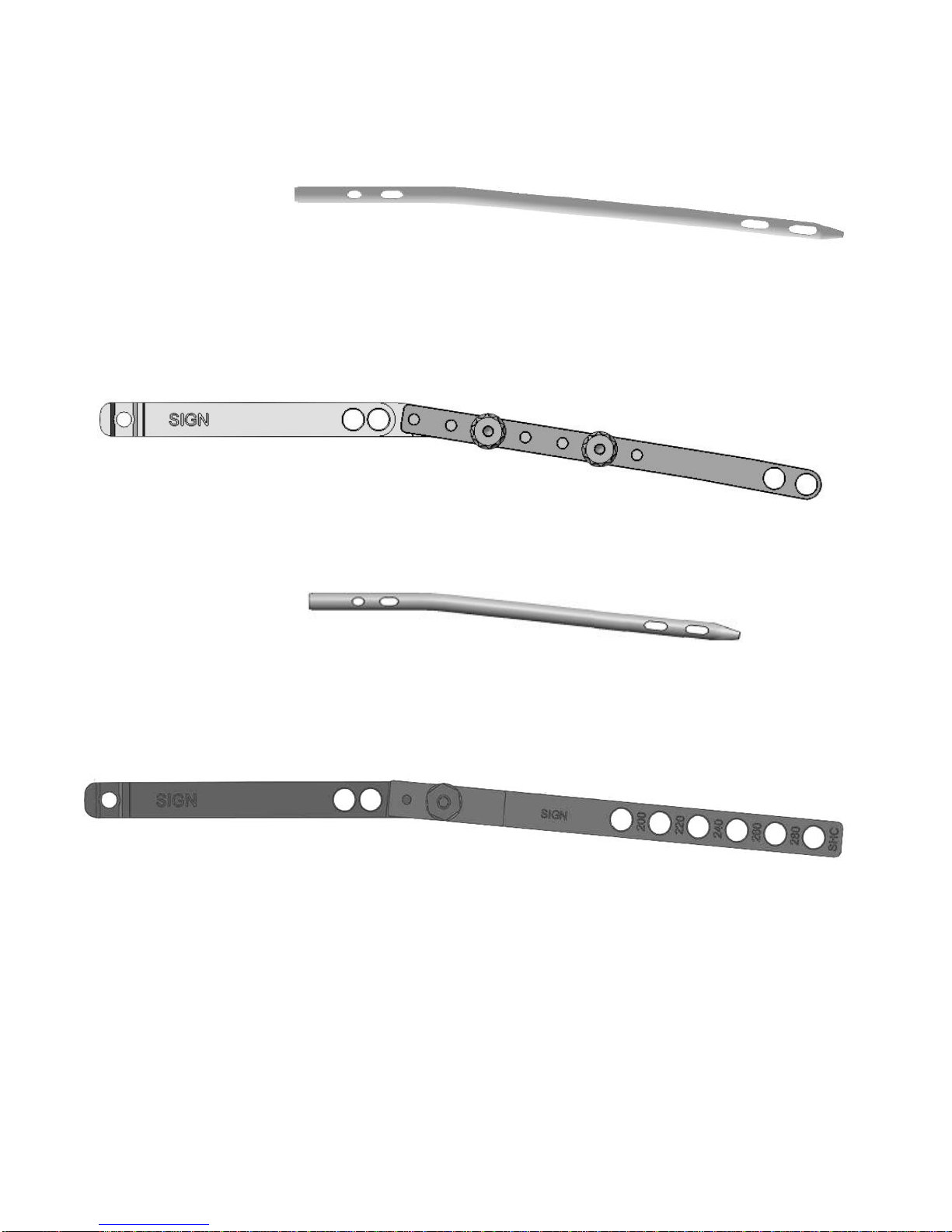
SIGN NAILS
Standard Length –Tibia/Femur
Diameter = 8mm, 9mm, 10mm, 11mm and 12mm
Length = 280mm, 300mm, 320mm, 340mm, 360mm, 380mm, 400mm and 420mm
Standard Target Arm
Short Length to be used with the Short Target Arm
Diameter = 8mm, 9mm, 10mm
Length = 220mm, 240mm and 260mm
Short Target Arm for Fin, Hip and Pediatric Nails
A solid nail decreases the risk of
infection. The 9º proximal bend can be
used in tibia, femur and humerus. The
1.5º bend makes canal penetration less
likely during insertion.

11
Technique for fractures in all locations
Patient Preparation
Check for open wounds
Check the patient the night before the operation for open wound. Remove cast the night before to
check skin condition. Cancel surgery if open wound is present. Wash the extremity the night before to
decrease skin bacteria.
Antibiotic prophylaxis
Start IV antibiotics 1 hour before surgery. Patients with open fractures should be given antibiotics as
soon after surgery as possible. Antibiotic should be given to patients with closed fractures one hour
prior to incision.
Pre-op scrub for surgeon and patient, Hexachlorophene is best, Betadine is less effective.
Soft tissue evaluation
If the fracture is open, the wound should be debrided, irrigated and evaluated as to whether wound
closure can be done. Factors that must be considered are contamination by virulent bacteria, high
energy vs. low energy trauma, foreign bodies. Virulent bacteria occur from “barnyard injuries” or
areas where bacteria are prevalent. The degree of injury is also determined by the forces that cause the
injury. These forces may destroy large amounts of muscle which leaves a dead space after
debridement. This dead space must be closed before the nail can be inserted. Therefore, the wound
classification is divided into wounds that can be closed without risk of infection, and those that can’t.
Whenever a wound can be closed without risk of infection, a nail can be inserted.
Reduction of closed fracture
Closed reduction can often be accomplished if the fracture is less than
7-10 days old. If closed reduction is attempted, check stability in all
planes prior to the reduction so you can test and compare the stability
after the reamer or nail is inserted. The reamers are passed into both
fragments followed by the nail.
Open reduction is necessary if the fracture is beginning to heal.
Transverse fractures can be reduced after both ends have been freed
from soft tissue. Figure 1 demonstrates one method. Allow the tissues
to slowly elongate during reduction. Figure 2 demonstrates
reduction of oblique fractures. Before reduction is
accomplished, ream both sides of the fracture site. Stop
reaming at the metaphysis.
The reamer should be turned 360º in clockwise direction
both during insertion and removal of the reamer from the
canal. The cutting edges of the reamer are damaged by
reaming counterclockwise or to-fro reaming. Save the bone
in a bone cup. Do not place on a sponge or in saline. Use
gradual distraction and allow time for the tissues to stretch.
Fig. 1
Fig. 2
12
Technique for use of SIGN Distractor (for full illustrated version see page 38)
Free up both ends of the fracture fragments
completely. The fracture fragments should be parallel
when the clamps are applied, figure 3. Once they are
applied, place the clamps through the ends of the
distractor and use the pins to stabilize them.
There is one movable side of the distractor and one
that is immobile. The immobile side of course would
be placed on the fracture fragment that is immobile
such as the proximal fragment of a fractured femur.
Begin ratcheting to distract the fragment. Go slowly
as the quadriceps will be very tight. Stop periodically
to allow the tissues to stretch.
Once the distraction has reached 4 inches, remove the distractor and replace the clamps so that they
are close together. This will put less stress on the
ratchet arm.
Once the clamps have been placed close together,
flex the knee to further stretch the quadriceps
mechanism. Begin the distraction again. If there is
a very tight band in the quadriceps, release it. Be
sure your rotation is proper as you distract the
fragments and they will soon fit together
anatomically, figure 4.
It is important to go slowly so that the tissues can
stretch.
Please give us feedback about the distractor as the
design is an ongoing innovation.
Fig. 3
Fig. 4
13
Open fractures
Adequate debridement is essential. The amount of tissue removed is dependent on vascular supply,
muscle damage, and bacterial contamination. Bone fragments that are completely devascularized
must be removed. Dead space must be closed. We must study proper timing of wound closure. If the
wound is cleaned and can be closed, the nail can be inserted. If not, external fixation is necessary. If
bone loss has occurred, consider methyl methacrylate insertion into the bone defect. At 6 weeks
remove the methyl methacrylate but do not disturb the membrane that formed. Place bone graft for
small defects. The membrane formed around the methyl methacrylate is bioactive and will accelerate
bone formation. Bone transport is used for large defects. If there is a large skin defect, consider
closing the wound with flaps. The nail should not be placed until the flaps are covered.
Reaming from bone entrance
Skin incision and location of bony entrance will be described in sections for specific fractures. Use
the reamers to extend the bone entrance hole into the diaphysis. Use the tissue protector to keep the
reamers from touching the skin. Ream until chatter and then select nail diameter 2mm smaller. Over
ream by 4mm for 4cm distal to the entrance hole. This will accommodate the bend in the nail. Apply
counter pressure as reaming becomes more forceful. Save the bone from the flutes of the reamer and
the fluid that comes out of the bone entrance when the reamer is withdrawn in a bone cup. It is best
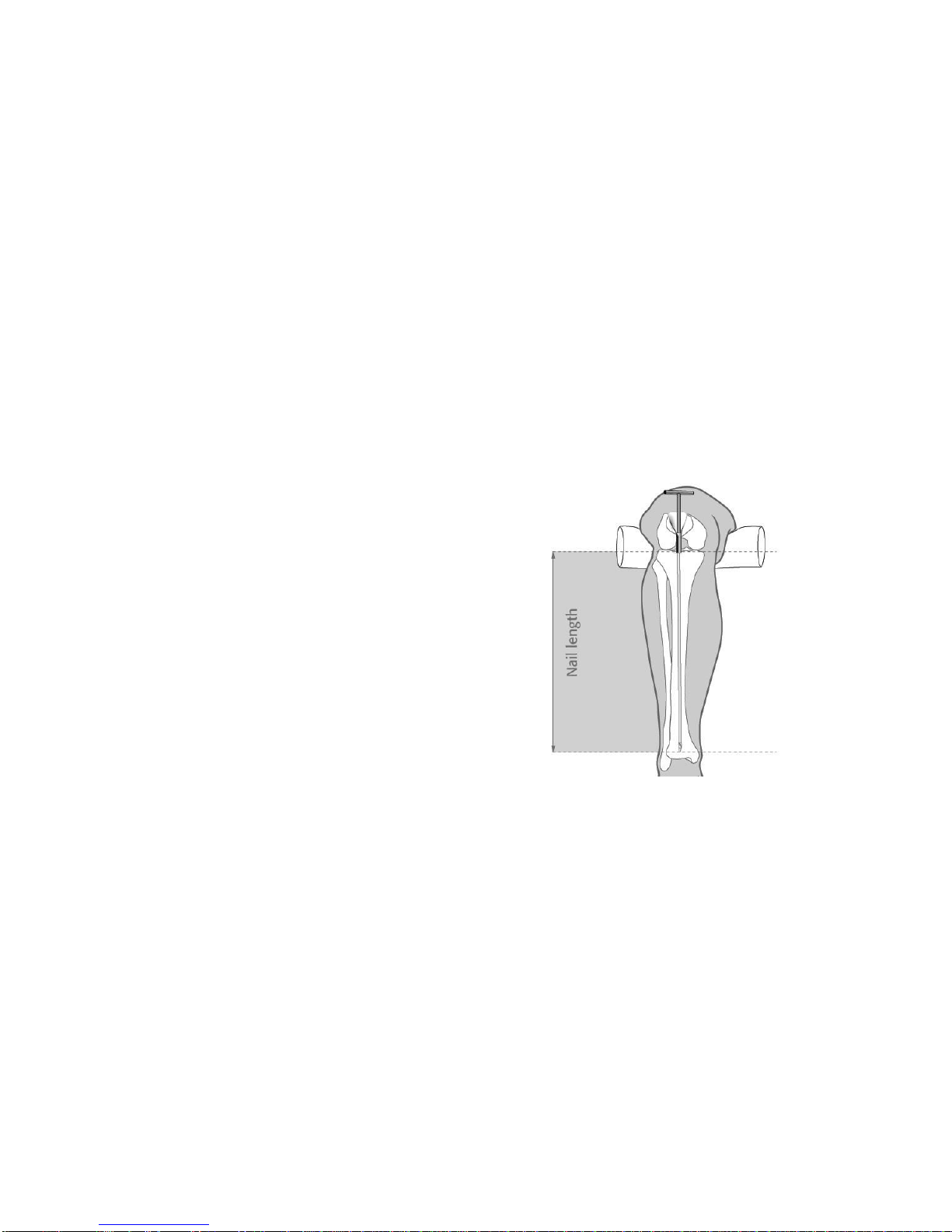
not to place this bone on a sponge or mix with saline.
If you are unsure that the reamer or nail is in the
canal of the distal fragment, push the reamer or
nail until resistance is encountered. If there is
no resistance, the reamer or nail is not in the
canal. The length of the nail is determined by
placing a blunt reamer down to subchondral
bone and measuring this length in the tibia,
figure 5. The femur length of the nail is
measured by estimation using another reamer.
The reamers are marked at 320mm to help
determine the length of the nail.
Blocking screws can be used to aid in inserting
the nail in proximal and distal fractures of femur and tibia.
Fig. 9
Reamer
Fig. 5

14
Nail Preparation
Assemble the Nail
Insert the locking bolt through the
hollow stem of the L-handle, figure 6.
Align the notches in the nail to the
corresponding protrusions on the stem
tube of the L-handle, figure 6. Be sure
the L-handle rests on the side for
proper interlock.
NOTE: Be sure the locking bolt rests as far down the stem tube as possible, figure 7.
Tighten the bolt into the nail, figure 7. If the locking is
not progressing easily through the L-handle and into
the nail, unscrew the locking bolt and reorient the
locking bolt so that it enters the canal of the nail easily.
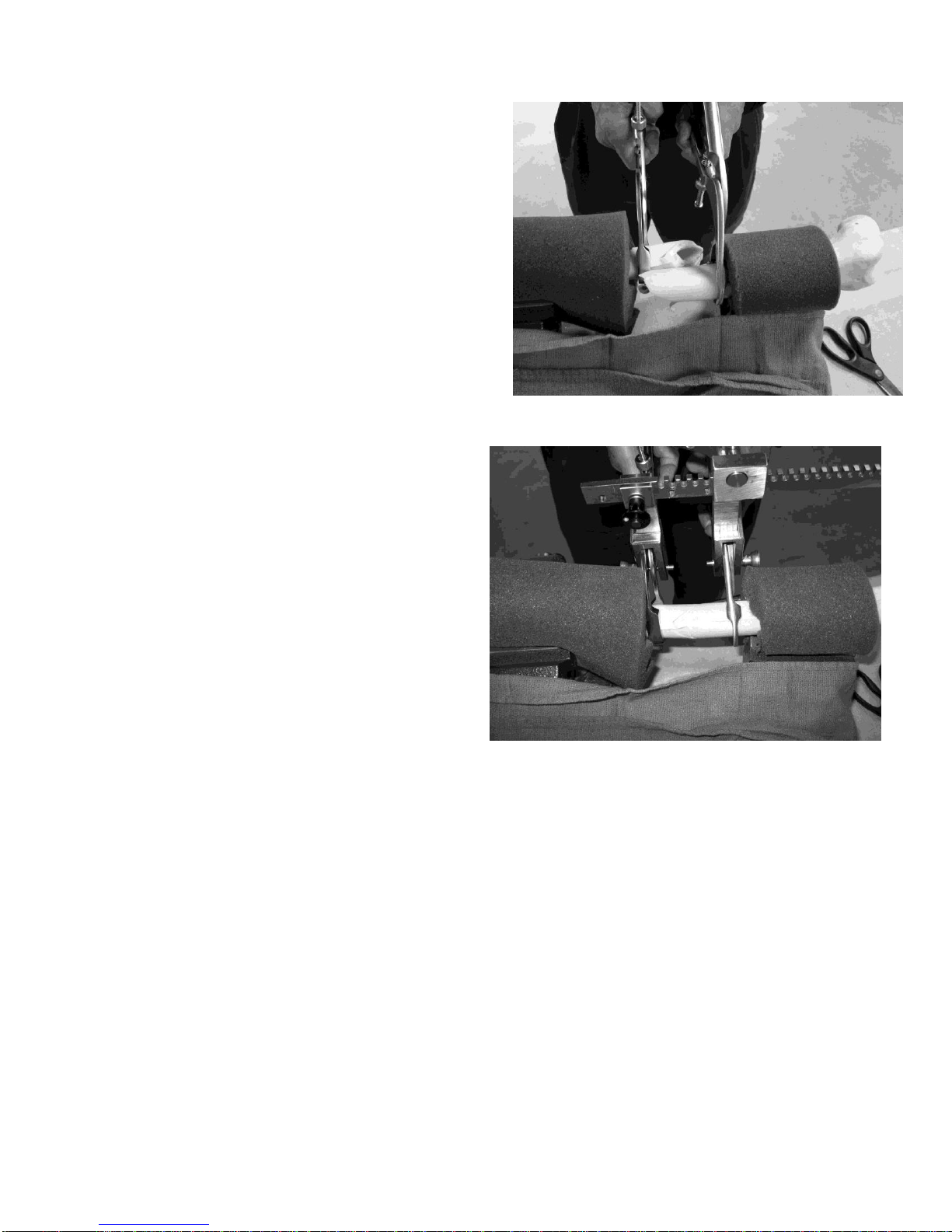
Attach target arm
Attach the assembled L-handle and nail to the
proximal target arm using the shoulder cap screw,
figure 8. Place the screw on the preferred side of the
L-handle for interlocking. Push the shoulder cap screw
in and carefully tighten by hand. Use the hex wrench
to secure the target arm to the L-handle. If the
shoulder cap screw does not turn easily, adjust the
junction between the L-handle and the target arm.
Attach distal target arm to proximal target arm
Place the alignment pin through the end hole in the distal target arm and distal slot in the nail, figure 9.
The distal cap screws are now
placed to connect the proximal and
distal target arms. Leave 2 holes
between the two distal cap screws
for stability. Withdraw the
alignment pin so only the tip is in
the slot to check alignment of the
target arm as the distal cap screws
are hand tightened. Use progressive
alternative tightening; tighten one
screw a little and then the other a little at a time, final tightening by hex wrench. Recheck alignment of
alignment pin to the slot.
Fig. 8
Fig. 9
Fig. 6
Fig. 7

15
Pearl: Insert caps screws downwards
The shoulder and distal cap screws are inserted easier if they are inserted in a downward direction so
the target arm is parallel to the floor and the cap screws are perpendicular to the floor. Removal is the
reverse. This avoids stripping the cap screw threads.
Remove the target arm
Remove the target arm from the L-handle,
leaving the L-handle attached to the nail,
figure 10.
Fig. 10

16
Nail Insertion
Use the tissue protector to prevent the
nail from touching the skin. Push the
nail into the canal as far as possible.
Many surgeons do not use a mallet to
insert the nail. If you decide to use a
mallet, use small taps and rotate the
nail 10º as it proceeds down the canal,
figure 11. Apply counter pressure to
allow advance. If the nail does not
advance with the small taps, consider
using a smaller diameter nail or
reaming more. Hitting the nail
forcibly will bend the nail and make
interlock more difficult.
Leave the proximal 3mm of the nail above the cortical bone to
provide additional stability. Remember the ring on the stem tube is
3mm above the nail, figure 12.
Distal Interlock
If you follow this technique, distal interlock without C-arm is
successful quickly in approximately 80% of your surgeries. Further
techniques to obtain distal interlock are listed after this technique.
Please send us your ideas.
The distal interlock is done before the proximal interlock so the nail
can be rotated to find the slot in the nail.
Reattach the target arm to the L-handle, figure 13.
Be sure the locking bolt is tight.
Decide whether you will use 1 or 2 interlocking
screws. If one interlocking screw is sufficient, place
the screw in the hole nearest the fracture. Use the
alignment pin to mark the location for the skin
incision. Be sure the skin incision is large enough
to place the cannula and your finger on the bone.
This finger is used to identify the location of the
cannula on the bone. If the cannula is directed by
the target arm so it does not hit the bone, loosen the
distal cap screws and adjust the target arm so the
cannula will direct the hole into the cortex. You
will find slot in nail for interlock by rotation of the
nail. Champher the hole with the screw hole broach
toward the bone.
Fig. 13
Fig. 11
Fig. 12

17
Incise the fascia but use the periosteal elevator
to spread the muscle down to the bone. Insert the
cannula on the bone, figure 14. Use a curved
clamp to remove soft tissue between the cannula
and the bone. Be sure no fascial bands are
pushing the cannula. Tap cannula lightly with a
mallet to secure to the bone.
Insert the small drill guide into the cannula and
use a small drill bit to drill a hole through the near
cortex. Avoid hitting the nail with the drill bit or it
will become dull.
Insert the large drill guide and use the step drill or
large drill bit to enlarge the pilot hole. Be sure the
step drill tip engages the pilot hole, figure 15.
Stop rotating the step drill or drill bit when it stops
suddenly after engaging in the slot of the nail.
Further twisting will break the step drill. If the step
drill does not progress, use the large drill bit.
Insert the solid slot finder through the hole
in the near cortex, figure 16. In hard bone
the screw hole broach inserted through the
cannula must be used to enlarge the hole
to allow the slot finders to enter the canal.
See figure 17 for comparison of screw
hole broach and step drill.
Push the solid slot finder with the flats in
the plane of the target arm. Rotation is not
used to place the slot finder. Push the slot
finder in. If the slot finder engages the slot
in the nail, 10-15º of rotation with a sharp
stop to the rotation will occur. This is the
“SIGN feel.”If the slot finder rotates 360º,
it is not in the slot or stuck in the hole in the cortex. Rotate the nail to orient the slot in the nail
parallel to the hole in the near cortex. If the solid slot finder enters the slot and the “SIGN feel” is felt,
place the cannulated slot finder. Test again for “SIGN feel.”
Fig. 14
Fig. 15
Fig. 16

18
Sometimes the cannulated slot finder will not proceed
through the hole in the near cortex because it is wider than
the solid slot finder. Use the screw hole broach to enlarge
the hole if this occurs.
If either slot finder does not enter the slot in the nail after
rotation of the nail, remove the target arm; use the
curved slot finder, figure 18, to locate the slot in the nail.
Find the slot in the nail by combination of rotation of the
nail by rotating the L-handle and slight pressure to push in
the curved slot finder. The surgeon should both rotate the
L-handle and manipulate the curved slot finder. Once the
slot in the nail has been discovered by “SIGN feel,”insert
the cannulated slot finder and drill the hole in the far
cortex.
If rotating the cannulated slot finder results in
the “SIGN feel,” place the small drill bit
through the cannulated slot finder to drill a
hole in the far cortex, figure 19.
Screw Hole Broach
Step Drill
Fig. 17
Fig. 18
Fig. 19
19
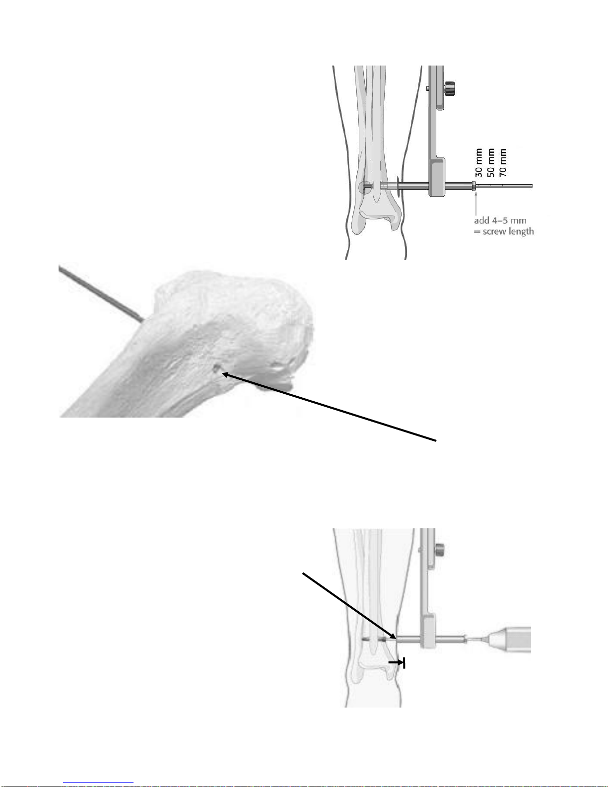
Measure the proper length of the screw by
placing the depth gauge through the cannulated
slot finder. Do not bend the depth gauge. The
depth gauge marks the hole. Remove the
cannulated slot finder and measure the depth of
the screw using the cannula and depth gauge,
figures 20a and 20b.
Add 5mm to the measurement so 2 threads can
be inserted through the far hole and the head of
the screw is 3mm prominent on the near cortex.
This will make screw removal much easier
should it be necessary.
Use your gentle tactile sense to determine when the tip is caught on edge of the hole.
Insert the screw through the holes in the cortex and
slot of the nail. Raise the cannula so the screw head
can be visualized in order not to insert the screw too
deeply, figure 21. Rotate the L-handle to be sure the
screw is in the slot after the screw has been inserted.
Compress the fracture as needed after the first
interlocking screw has been placed, see page 21.
Fig. 21
Fig. 20b
Fig. 20a

20
Tips for interlocking
If either slot finder will not rotate after being placed into the hole in the near cortex, enlarge the hole
with the screw hole broach. Often bone will remain in the hole even though the step drill enters the
slot in the nail.
If the slot finder does not enter the slot in the nail, remove the target arm and use the curved slot
finder. This step is necessary approximately 20% of the time. Place the curved slot finder through the
hole in the near cortex and find the nail by tapping on it. Rotate the nail so the slot in the nail is
parallel with the hole in the cortex. If the curved slot finder partially enters the slot, rotate the nail to
allow it to fully enter the slot. Confirm location of the slot by using the solid slot finder and then the
cannulated slot finder. Once the cannulated slot finder has been placed and confirmed by the “SIGN
feel,” drill the hole in the far cortex. Measure and place the screw.
If the curved slot finder does not enter the slot, check the longitudinal orientation. Be sure the
reduction has not slipped. This will misalign the longitudinal orientation of the hole in the cortex and
slot of the nail. Correct this misalignment and place the slot finder. Check to be sure the nail has not
migrated proximally or distally which will also misalign the hole and slot in the longitudinal plane.
After placing the target arm on the L-handle, sometimes the cannula directs the small drill guide so it
is not in contact with the bone cortex. If this occurs, loosen the distal cap screws and adjust the target
arm so the pilot hole is directed through the cortex. In the femur this occurs in the anterior plane and
in the tibia the posterior plane. Proceed with enlarging the hole in the near cortex and use the curved
slot finder to find the slot in the nail. Sometimes it is necessary to champher the hole with the screw
hole broach to allow slot finder to enter slot in nail. Rotate the nail by rotating L-handle to position
slot in nail parallel with hole in near cortex.
Table of contents
Popular Medical Equipment manuals by other brands


Rhythm Healthcare
Rhythm Healthcare LM5BA manual

PHOTON SOUND BEAM
PHOTON SOUND BEAM Complete operating guide

Stanley Healthcare
Stanley Healthcare WanderGuard BLUE user guide

Derungs
Derungs D med VISIANO 20-2 C T1 Installation and operating instructions

dynarex
dynarex 10520 manual

EKOM
EKOM DK50 DE Instructions for use