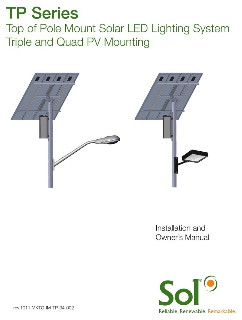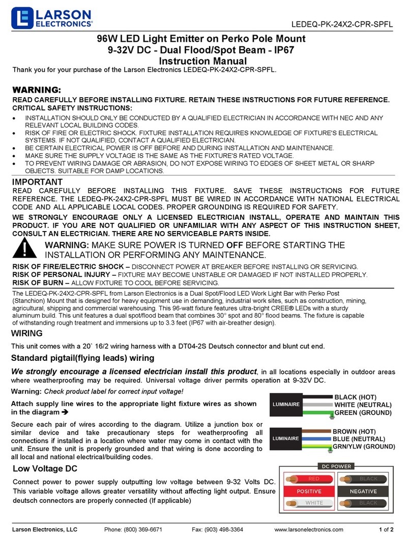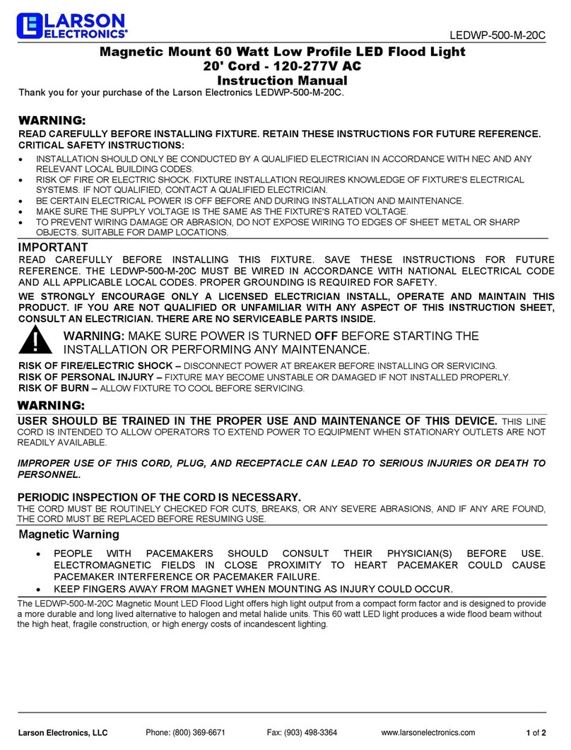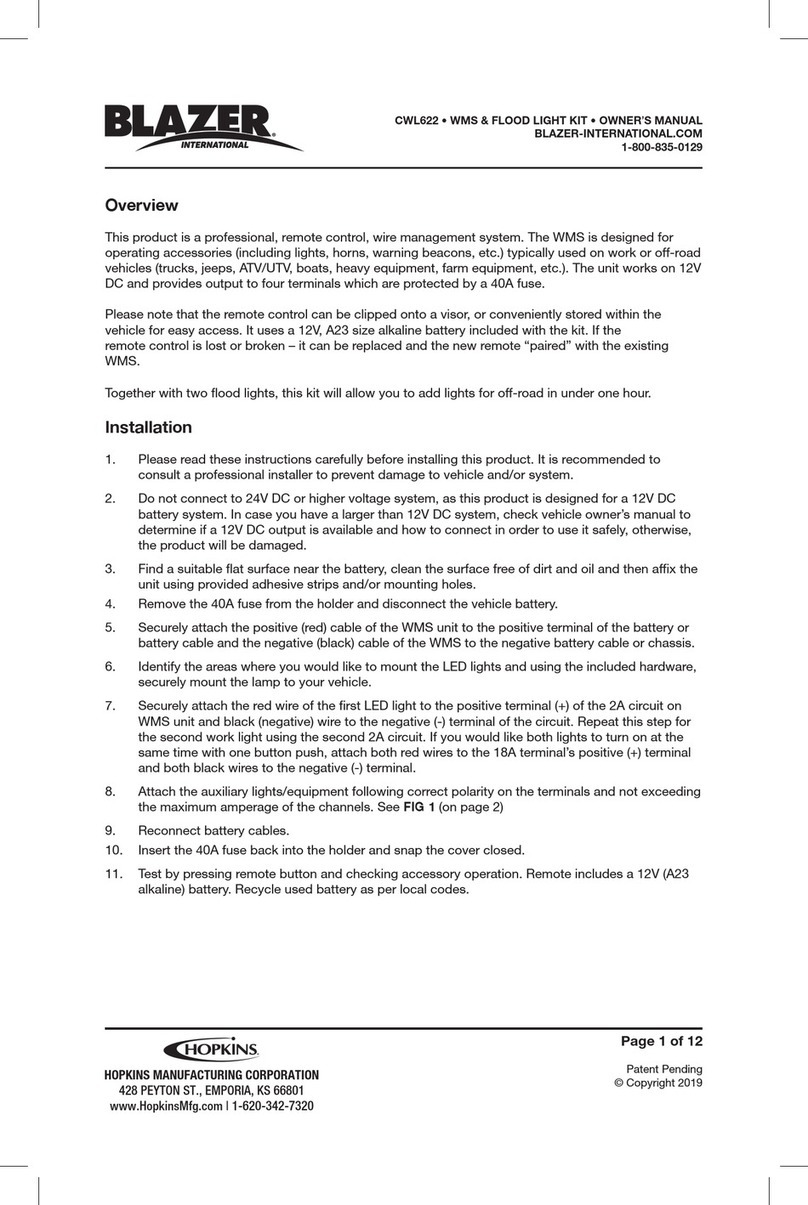
INSTALLATION
1. Turn OFF Power at circuit breaker box.
Do not rely on wall switch alone to
turn off power.
CAUTION:
2. Use the wire pass through the Sponge Foam(8).
3. Connect the black fixture lead to the voltage
supply lead with supplied Wire Nuts(7).
CAUTION: WIRING AND FIXTURE OPERATION
Make sure power is turned off.
4. Connect the white fixture lead to the neutral
supply lead with the supplied Wire Nuts(7).
5. Connect the green or bare copper ground lead
to the supply ground lead with the supplied Wire
Nuts(7).
Note: If house wiring does not include a ground
wire, consult your local electrical code for approved
grounding methods.
For proper connection, place wire nut over wires
and twist clockwise until tight.
6. Install Screw (4) into 2 side hole of Back
Plate(6) with Sponge Foam(8) on outletbox.
7. Loosen the Adjustment screw(2) connected to
the arm knuckle to aim the fixture up or down.
Loosen Locknut(3) to secure the LED light(1) in the
desired position.
8. Turn on electricity at fuse or circuit breaker box
and verify success of installation.
9. Apply silicone caulking (not included) around
the perimeter of the Mounting Plate where it
contactsthe mounting surface for moisture seal.
Note:
This device is not intended to be used
with any external dimmer, timer or photo-
control.
Fixture is intended for Wall mount above
4 ft (1,2m) only. Do not mount on ground!
Page 4
Page 5 Page 6
MOTION SENSOR
OPERATING INSTRUCTIONS
CAUTION:
Make sure motion detector head is not UPSIDE
DOWN! Turn the head so the controls face the
gound. If the head is turned upside down, the
motion detector can be damaged by rain!
If this fixture fails to operate properly, use the
guide below to diagnose and correct the problem.
If light does not come on:
• Verify that power is turned on at switch and
breaker
• Verify that fixture is wired properly
• Verify that line voltage is correct.
If further assistance is required, contact:
Technical Support at:
86 571 82151572
This LED light provides low maintenance service
with no bulbs to change. Clean surfaces with a
mild soap and water. Do not use abrasive materi-
als such as scouring pads or powders, steel wool
or abrasive paper.
WARNING: There are no user serviceable parts
inside lamp head. Do not remove or disassemble
lamp head. This will woid Warranty.
TIMER/TEST
The TIMER/TEST knob is used to switch between TIME and
TEST mode for testing the coverage area. The TIMER/TEST
knob also sets the ON time that the light will stay on after
motion is detected during TIME mode. A photocell is built
into the TIME/TEST knob to automatically shut off the light
during daylight hours. In TEST mode the photocell is
turned off so the light can come on during daylight
hours for testing the coverage area.
TEST Mode:
• To enter TEST mode, Turn the knob fully counterclockwise
so the pointer is aimed at the word “TEST”. Turn on the
power,after WARM-UP TIME(Red indicator in sensor is off),
to enter TEST mode.
• To leave test mode, turn the knob clockwise away from
TEST Position.
Note:
When the TIMER/TEST knob is set to TEST, the light will
come on after motion is detected and will then shut off after
5±3 seconds of final motion detection.
Auto Mode:
To enter Auto mode, simply turn the knob clockwise away
from the TEST setting. (The red indicator in sensor, will
flicker 1 second)
At dusk, Natural light reaches the start value
(LUX:50-250LUX), the light will come on after motion is
detected.
Turn the knob to adjsut ON TIME:
Min. 10±5 sec Max. 300±90sec
Manual Override Mode:
MANUAL OVERRIDE To disable the motion sensor and
keep the light continuously on for the night, flip the wall
switch off for 0.5-3 seconds and then back on. To reset to
Security mode, flip switch again off for 0.5-3 seconds and
back on. If you leave the light on all night it will automatically
turn off at dawn and reset to Auto Mode.
SENSITIVIY
The SENSITIVIY knob adjusts the fixture’s sensitivity to
motion. Turn the knob clockwise to increase sensitivity
and counterclockwise to reduce the sensitivity. The most
common setting is fully cockwise to maximum sensitivity.
RED LED INDICATOR LIGHT
A red LED indicator light in the motion sensor head comes
on when motion is detected.
I
T
I
V
I
T
Y
S
N
E
S
T
I
M
E
R
TEST
Detection Range: 5 ft. to 60 ft.
with max. 180° detection angle
TOPELE.NET


