Topline TOP-FLO TF-C Series User manual

TOP-FLO®
Centrifugal Pump Model “TF-C” Series
www.toplineonline.com
Operation
Maintenance
& Parts List
Please read and understand this
manual prior to installing, operating
or maintaining this pump.

SAFETY ...................................................................................1
WARRANTY.............................................................................2
GENERAL INFORMATION......................................................2
Shipping Damage ..............................................................2
Hidden Damage.................................................................2
Warranty Claim ..................................................................2
Ordering/Returning Parts..............................................22
INTRODUCTION ................................................................. 3-4
Description of Components...............................................3
Performance Characteristics .............................................4
Standard Construction.......................................................4
Mechanical Specifications .................................................4
Motor Frame Sizes.............................................................4
INSTALLATION.................................................................... 5-7
Pump Dimensions..............................................................5
Unpacking..........................................................................6
Pump Location...................................................................6
Pump Leveling ...................................................................6
Supply and Discharge Piping/Valves .................................6
Electrical Connections .......................................................7
Flush Seal Option ..............................................................7
Cleaning Pump Prior to First Operation.............................7
OPERATION ........................................................................ 8-9
Cleaning Safety Procedures ..............................................8
Preliminary Test Run ..........................................................8
Operation ...................................................................... 8-9
MAINTENANCE............................................................... 10-20
Stub Shaft Seal................................................................10
Service/Repair .................................................................10
Disassembly for Cleaning and Repair........................ 11-12
Replacing Motor ..............................................................12
Install Adapter/Stub Shaft Adjustment ............................13
Drive Collar Adjustment ...................................................14
Disassembly for “DG” Seal ..............................................15
Reassembly for “DG” Seal (setting the drive collar ... 16-17
Disassembly and Reassembly for “E” Seal ............... 18-20
Routine Maintenance.......................................................20
TROUBLESHOOTING AND CAUSES ..................................21
PARTS ORDERING/SPARE PARTS/PARTS LIST.......... 22-28
Water Cascade Assembly Parts ......................................23
Repair Seal Kits, (All pumps ............................................23
TF-C100……. (With spare parts ......................................24
TF-C114……. (With spare parts ......................................25
TF-C216……. (With spare parts ......................................26
TF-C218……. (With spare parts ......................................27
TF-C328……. (With spare parts ......................................28
TABLE OF CONTENTS

1
TOP-FLO®“TF-C” Series centrifugal pumps have been designed to be safe and
reliable when properly used and maintained.
Operators and maintenance personnel must follow safety measures. Failure
to observe the instructions in this manual could result in personal injury or
machine damage.
• Do Not operate pump beyond the rated conditions for which the pump
was sold.
• Do Not use heat to remove impeller or disassemble pump due to risk of
explosion of trapped liquid.
Warnings, cautions and notes are contained in this manual. To avoid serious injury and/or
possible damage to equipment, pay attention to these messages.
WARNING Hazards or unsafe practices which COULD result in severe personal
injury or death and how to avoid it.
CAUTION Hazards or unsafe practices which COULD result in minor personal
injury or product or property damage.
NOTE Important information pertaining directly to the subject. (Information
to be aware of when completing the task.)
WARNING
ROTATING SHAFT
DO NOT OPERATE WITHOUT
GUARD IN PLACE
Read and understand this manual prior
to installing, operating or maintaining this
pump.
SAFETY
WARNING
Do not operate pump
without CASING/VOLUTE
clamped securely in place.
WARNING
To avoid electrocution, ALL electrical should
be done by a registered Electrician, following
Industry Safety Standards. All power must be
OFF and LOCKED OUT during installation.
WARNING
TO AVOID POSSIBLE SERIOUS
INJURY, SHUT OFF AND DRAIN
PRODUCT FROM PUMP PRIOR TO
DISCONNECTING PIPING.
WARNING
TO AVOID SERIOUS INJURY, DO NOT
INSTALL OR SERVICE PUMP UNLESS ALL
POWER IS OUT AND LOCKED OUT.
CAUTION
Wear gloves to avoid cutting
injuries from sharp pump parts.
2
TOP LINE PUMP WARRANTY
Seller warrants its products to be free from defects in materials and workmanship for a period
of one (1) year from the date of shipment. This warranty shall not apply to products which
require repair or replacement due to normal wear and tear or to products which are subjected
to accident, misuse or improper maintenance. This warranty extends only to the original Buyer.
Products manufactured by others but furnished by Seller are exempted from this warranty and
are limited to the original manufacturer’s warranty.
Seller’s sole obligation under this warranty shall be to repair or replace any products that Seller
determines, in its discretion, to be defective. Seller reserves the right either to inspect the
products in the field or to request their prepaid return to Seller. Seller shall not be responsible
for any transportation charges, duty, taxes, freight, labor or other costs. The cost of removing
and/or installing products which have been repaired or replaced shall be at Buyer’s expense.
Seller expressly disclaims all other warranties, express or implied, including without limitation
any warranty of merchantability of fitness for a particular purpose. The foregoing sets forth
Sellers entire and exclusive liability, and Buyer’s exclusive and sole remedy, for any claim of
damages in connection with the sale of products. In no event shall Seller be liable for any special
consequential incidental or indirect damages (including without limitation attorney’s fees and
expenses), nor shall Seller be liable for any loss of profit or material arising out of or relating to the
sale or operation of the products based on contact, tort (including negligence), strict liability or
otherwise.
GENERAL INFORMATION
SHIPPING DAMAGE
Inspect your shipment immediately. If shipping damage is found, note it on the drivers copy
(packing slip) and request the driver to ask the Inspector to call. You are responsible for
initiating shipping damage claims.
HIDDEN DAMAGE
If during installation, you discover hidden damage caused in shipping, contact the Shipper
immediately and ask for an Inspector to call. Notify your Top Line Distributor of the problem.
WARRANTY CLAIM
Please read the Warranty statement to correctly determine if you have a claim. In warranty
claims you must have a “Returned Goods Authorized” (RGA) from Top Line before any
returns will be accepted. Your Top Line Distributor will help you with a warranty problem.
ORDERING/RETURNING PARTS
See page 24 for complete information on ordering parts. Complete the Distributor/Product
information immediately and keep for later reference.
WARRANTY
3
INTRODUCTION
DESCRIPTION
This manual contains installation, operation, cleaning, repair instructions and parts lists
for the “TF-C” Series Centrifugal Pumps. It also provides a Troubleshooting Causes
chart to help in determining and correcting possible pump problems.
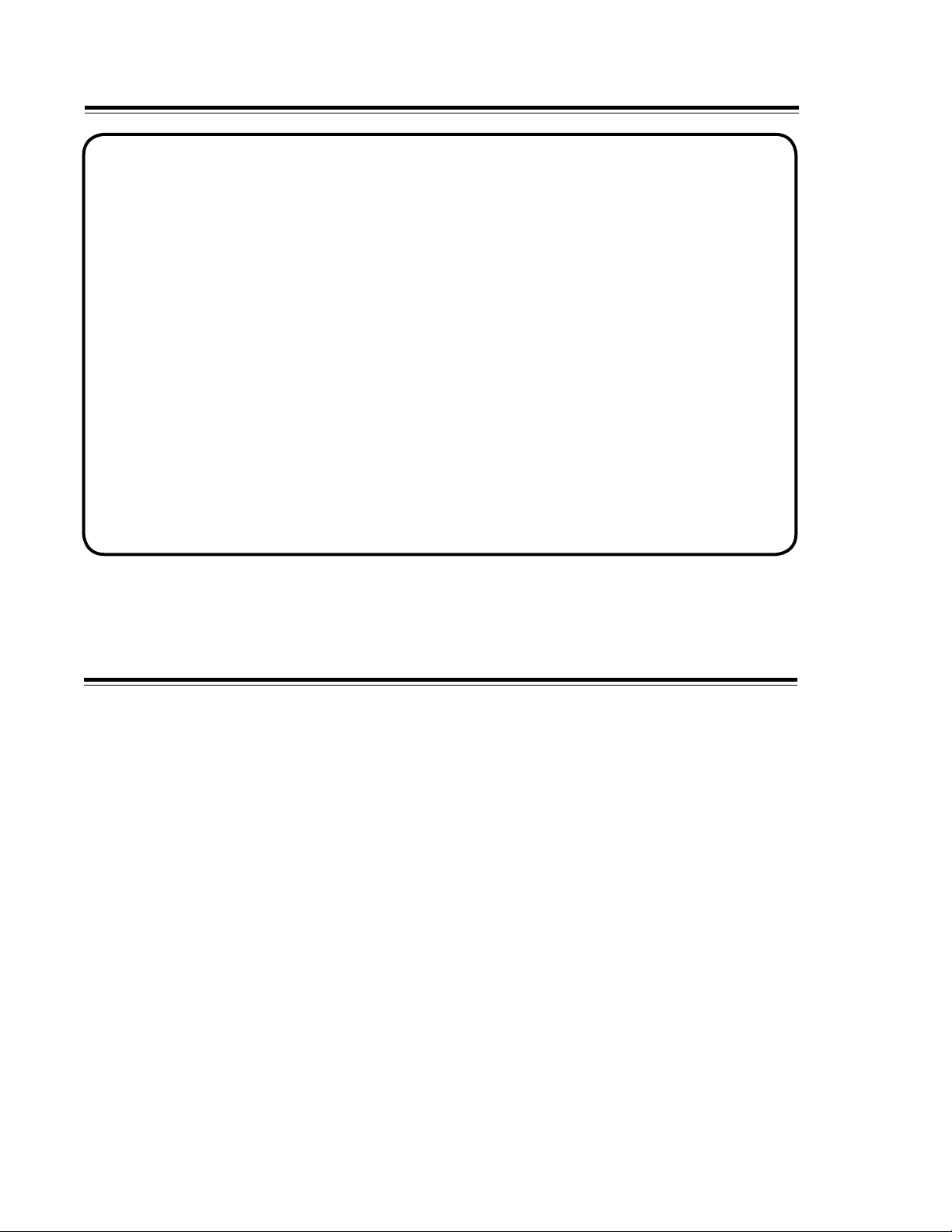
The “TF-C” Series Centrifugal Pumps consist of two sections, the motor assembly, and the
pump components. (Figure 1) The pump is mounted on the drive motor with an adapter, and
is coupled to the motor with a stainless steel stub shaft. The pump impeller mounts on the
stub shaft and is secured with a floating impeller retainer pin.
The casing is joined to the adapter by a clamp, greatly simplifying removal and also
permitting the casing outlet to be rotated to various positions. (The TF-C 100 is secured with
two wing nuts and may only be mounted with the outlet facing straight up.) The mechanical
external balanced seal assures a long wear life. The drive motor is mounted on a frame with
adjustable legs in accordance with sanitary design requirements providing simple installation
and easy leveling of the pump.
40
6D
*80CA
*80A
*80B
*80 2
75K
1
*90
11
71B
71
*24
6A
CLAMP
TF-C100

4
STANDARD CONSTRUCTION:
• Casting, backplate, and impeller are 316L stainless steel with a 32Ra grit polished sanitary
finish.
• Port Connection: Clamp fittings are standard.
• Power: Supplied by a standard foot-mounted C-face motors through 60 horsepower.
• Seal: “Type D” Seal material is carbon rotating on stationary stainless steel backplate.
Water cascading attachment is available option (“F” Seal.) Dual seal is available option
(“E” Seal.)
• Elastomers: Buna, FKM and EPDM.
PERFORMANCE CHARACTERISTICS:
Nominal Capacity: To 780 GPM Viscosity: To 1500 CPS Temperatures: To 212°F (100°C)
Nominal Speeds: To 2900 RPM - 50HZ; To 3500 RPM - 60HZ
MECHANICAL SPECIFICATIONS
PORT SIZE
Inches
IMPELLER DIA.
Inches (mm)
MODEL Inlet Discharge Minimum Maximum
TF-C100 1-1/2
-
1
-
3.0
(76)
3.68
(93)
TF-C114 1-1/2
2
1-1/2
1-1/2
2.5
(63)
4.0
(101)
TF-C216 2
2-1/2
1-1/2
1-1/2
4.0
(101)
6.0
(152)
TF-C218 2
3
1-1/2
1-1/2
6.0
(152)
8.0
(203)
TF-C328 3
4
2
2
5.5
(139)
8.0
(203)
AVAILABLE MOTOR FRAME SIZES FOR PUMP MODELS
TF-C100 56C
143TC-145TC
TF-C114 56C
143TC-145TC
182TC-184TC
TF-C216 56C
143TC-145TC
182TC-184TC
213TC-215TC
254TC-256TC
TF-C218 143TC-145TC
182TC-184TC
213TC-215TC
254TC-256TC
284TC-286TC
TF-C328 182TC-184TC
213TC-215TC
254TC-256TC
284TC-286TC
324TC-326TC
INTRODUCTION

5
INSTALLATION TOP-FLO®CENTRIFUGAL PUMP DIMENSIONS
6
INSTALLATION
UNPACKING EQUIPMENT
Check all parts received and inspect for damages that may have occurred during shipping.
Report any damage to the carrier.
PUMP LOCATION
• Place as close as practical to the liquid
supply. Keep supply piping short and
straight. Keeping the pump supplied with
liquid will prevent damaging from cavitation.
• The pump must be accessible for service
and inspection during operation.
• The motor must be protected from flooding.
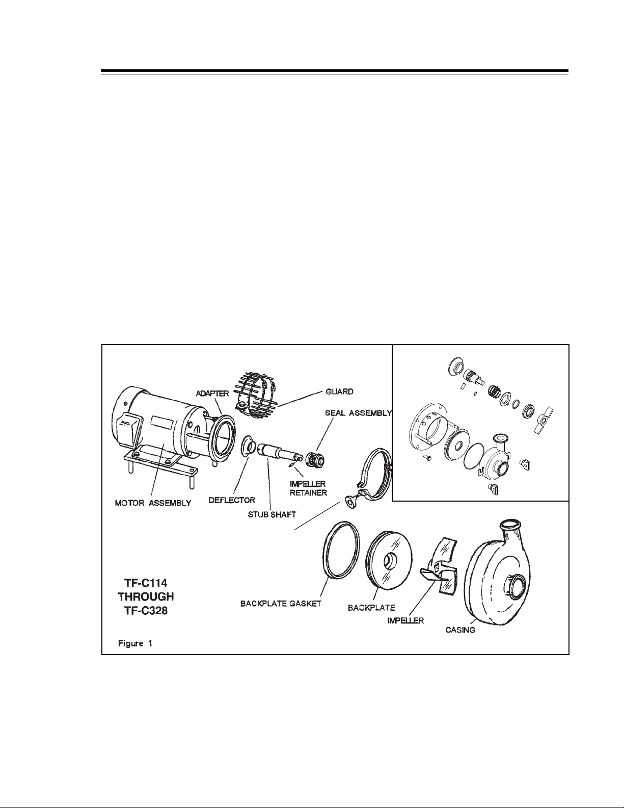
PUMP LEVELING
• Level the pump by rotating the adjustable
legs. (Figure 3)
SUPPLY AND DISCHARGE PIPING/VALVES
• Use line size equal to, or larger than
connection sizes on pump, especially the
inlet supply line.
• Keep the supply line short and straight. Use
as few elbows, valves, or other types of
restrictions as possible. Avoid up and down
rises which will trap air.
• Be certain all joints in the suction lines are
well sealed to prevent air leaks.
• Maintain a straight length of pipe at least 4
diameters long at the pump inlet. (Figure 4)
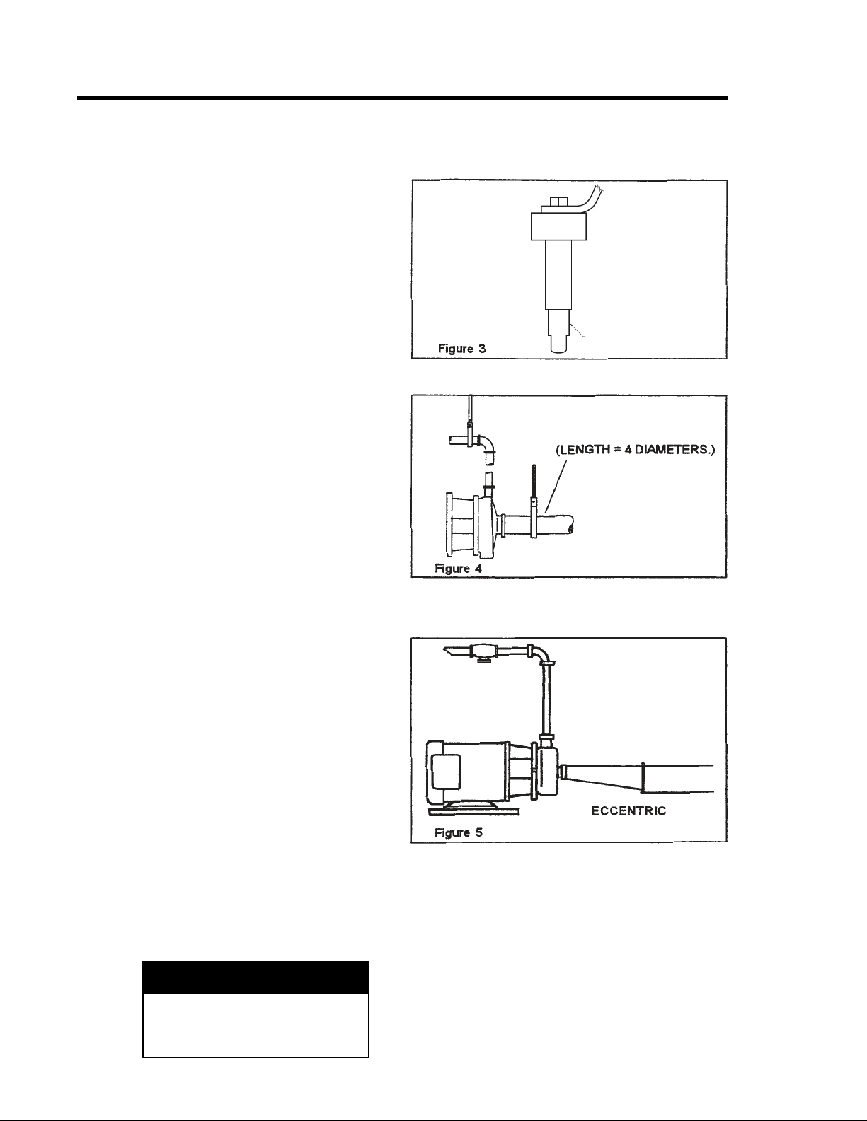
• The pump casing may be rotated with
the discharge connection pointing in any
direction. The best pump performance will
be with the outlet up, to the left, or positions
in between. These positions insure the
casing is flooded and prevents problems
due to air in the system. (Figure 6)
• Support the supply and discharge piping
near the pump so no strain is put on the
pump casing.
• If an expansion joint is used, install a pipe
anchor between it and the pump.
• If a reducer is connected to the inlet, use
an eccentric type (Figure 5) to prevent
problems due to trapped air.
ADJUSTABLE LEGS
CAUTION
Wear gloves to avoid cutting
injuries from sharp pump and
piping parts.
• Line slope will depend on application
requirements. The best pump operation
is with supply line sloped slightly upward
toward pump to prevent trapped air. If the
system must drain into the pump casing,
keep downward slope to a minimum or
priming problems may occur.
• Install shutoff valves to isolate pump from
supply and discharge lines to allow pump
service without draining the system.
ADJUSTABLE LEGS
ADJUSTABLE LEGS
7
installed above the supply liquid level. Install
INSTALLATION
• This pump is not self-priming. The pump is
installed above the supply liquid level. Install
a foot valve or other system check valve to
keep casing flooded for priming. (Figure 7)
• A throttling valve may be required to control
the pump flow rate to prevent motor
overload. Always install the throttling valve
in the discharge piping, never in the supply
piping, and at least 10 diameters from the
pump outlet (Figure 7)
ELECTRICAL CONNECTIONS
WARNING
To avoid electrocution, ALL electrical
installation should be done by a registered
electrician, following Industry Safety
Standards. All power must be OFF and
LOCKED OUT during installation.
• Read the manufacturer’s motor instructions
before making installation. Follow the
manufacturer’s lubrication schedules.
• Check the motor nameplate to be sure
the motor is compatible with the electrical
supply and all wiring, switches, starters,
and overload protection are correctly sized.
• Check pump rotation following electrical
installation. Correct rotation is counter
clockwise when facing pump inlet
connection. (Figure 5)
FLUSH SEAL OPTION
When this option is ordered, a fitting
assembly is supplied for directing a flow
of water onto the backplate/seal area. The
water supply should be cool and filtered. If
the product solidifies at cool temperatures,
use warm or hot water. The connection size
is 1/4 inch O.D. tubing and the required flow
is approximately 5 U.S. gallons per hour.
(Figure 8)
WARNING
TO AVOID SERIOUS INJURY, DO NOT
INSTALL OR SERVICE PUMP UNLESS
ALL POWER IS OFF AND LOCKED OUT.
CLEANING PUMP PRIOR TO FIRST
OPERATION
CLEAN PUMP AND PIPING
Disassemble pump and clean all product
contact parts and seals prior to first operation.
Follow instructions in the “Cleaning Safety
Procedures” and “Disassembly for Cleaning
and Repair” section (pages 9 and 12).
The pump should be thoroughly cleaned of any
materials which may have accumulated during
installation.

8
CLEANING SAFETY AND TEST RUN
AMMETER TEST
Operate pump under process conditions and
check motor amp draw versus nameplate full
load rating. If amp draw exceeds motor rating,
a system change or pump change is required.
If process conditions and/or liquid changes,
(higher viscosity, higher specific gravity)
recheck motor amp draw.
Contact your authorized TOP LINE distributor
for assistance.
WARNING
TO AVOID ELECTROCUTION, ONLY
A QUALIFIED ELECTRICIAN SHOULD
INSTALL THE AMMETER.
OPERATION
• Any system throttling valves, or similar
devices used to control flow rate must
be installed in the discharge line, not the
supply line. Restriction in the supply line
may cause cavitation and pump damage.
• “Water hammer” in the system can
damage the pump and other system
components. Water hammer often occurs
when valves in the system are suddenly
closed causing lines to move violently and
with a loud noise. When this condition is
present, find and eliminate the source of
the water hammer. One way to eliminate
water hammer is to slow down the
actuation speed of the valve.
• Do not expose the pump to freezing
temperatures with liquid in the casing.
Frozen liquid in the casing will damage
the pump. Drain casing before exposing
to freezing temperatures.
DISASSEMBLY, CLEANING/REPAIR
OPERATION
CLEANING SAFETY PROCEDURES
Manual Cleaning:
1. Do not use toxic and/or flammable solvents.
2. Lock out electrical power and shut off all air
prior to cleaning equipment.
3. Keep electrical panel covers closed and
power off when washing equipment.
WARNING
To prevent an accidental start-up
the power source should be locked
out using your lock and key.
4. Clean up spills as soon as possible.
5. Never attempt to clean the equipment while
it is operating.
6. Wear proper protective apparel.
Cleaning-In-Place
1. Make certain that all connections in the
cleaning circuit are properly applied and tight
to avoid contact with hot water or cleaning
solutions.
2. When the cleaning cycle is controlled from
a remote or automated cleaning center,
follow all established safety procedures for
servicing the system.
PRELIMINARY TEST RUN
See OPERATION on page 10 to set pump up
for a test run.
CHECK FOR POSSIBLE MOTOR
OVERLOAD CONDITION
Certain combinations will overload the motor
when operated with open, unrestricted
discharge, which results in a high flow rate.
Additional discharge restriction may be required
to lower the flow rate and lower the horsepower
requirements. DO NOT add restrictions to the
supply line. If the pump was incorrectly sized, a
smaller impeller or a higher horsepower motor
may be required.
If uncertain about pump selection and
application, temporarily install an ammeter in
the electrical service to check the amp draw.
It is not necessary to disassemble the pump for
cleaning if used in a CIP Installation (Clean-In-Place).
However, periodically take pump apart, thoroughly
inspect, clean and reassemble.
(See MAINTENANCE - DISASSEMBLY)
9
8. Slowly open the discharge valve until
desired flow is obtained. Observe pressure
gauges and if pressure is not attained
quickly, stop pump and prime again.
STOP PUMP
9. To stop the pump, shut off the power to
the pump motor. Liquid in the system can
flow freely through the pump. The pump
does not act as a shut off valve. Shut off
supply and discharge lines.
OPERATION
WARNING
Skin and eye protection are required
when handling hazardous or toxic fluids.
CAUTION
If pump is being drained, take necessary
precautions to avoid personal injury.
NOTE: Disposal of drainage must be in
conformance with environmental regulation.
Pumps must have been correctly installed as
described in the “INSTALLATION” section.
SEAL FLUSH
1. If the pump has the flush seal option, start
the flow of flush water (approximately 5 US
gallons per hour recommended rate).
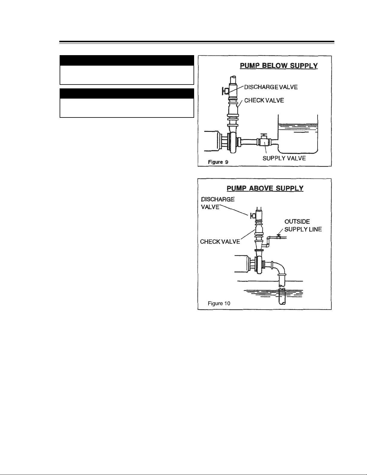
PRIME PUMP
2. Flood the pump casing with liquid BEFORE
starting pump to avoid damage to the pump
parts. Fill the supply tank with liquid and
open supply line valve (suction). Any air
trapped in the supply line or casing should
be vented. (Figure 9)
PRIMING WITH OUTSIDE SOURCE
The pump will not self prime if the liquid
supply is below the pump level. (Figure 10)
3. Close the discharge valve and open the air
vents.
4. Open the valve in the outside supply line
until the liquid flows from the vent valves.
5. Close the vent valves and the supply line.
Use a type of check valve system to keep
the supply line and pump casing flooded
with liquid. Otherwise, the pump must be
primed before each operation. (See Figure 7)
6. Start the pump motor.
PUMP CHECK
7. Check to see that liquid is flowing and all
piping connections and seals are leak free.
The pump must be operated against a
closed discharge for a short time. However,
continued operation will heat liquid in casing
to boiling and lead to pump damage.

10
STUB SHAFT SEAL
The shaft design utilizes a drive collar as
shown in Figure 11 to assure proper loca-
tion of the seal assembly. The TF-C100 does
not require a drive collar. The drive collar is
incorporated in the design of the stub shaft.
The drive collar must be properly located on
the shaft, following procedures outlined on
page 15.
This type of seal should be replaced when
the face is worn away, or when leakage is
noted (Figure 12)
To remove the seal, disconnect the suction
and discharge piping. Then, remove the
casing, impeller, and backplate. Protect the
sealing face of the backplate from nicks and
scratches.
NOTE: When the carbon seal is replaced,
the position of the drive collar should be
checked and reset if necessary, per the
dimensions given on page 15.
Inspection during cleaning will determine
if the carbon seal needs replaced. No
additional drive collar adjustment is
necessary unless the seal is replaced.
(Figure 12)
SERVICE/REPAIR
Periodically inspect all parts of the pump
to prevent malfunctions caused by worn or
broken parts.
MAINTENANCE SEAL SERVICE
11
d assembly with a
Loosen clamp wing nut and swing clamp
Inspect clamp saddles and the casing for
eplace if necessary.
etaining pin in the center of the stub
shaft. This will allow the impeller to pull off
Remove the backplate gasket and inspect
e must be taken to protect the
sealing face and edges of the backplate
Remove the carbon seal, o-ring, seal cup,
om the stub shaft by pulling
carbon seal for signs of abrasions, cuts,
or other wear that could cause leakage.
the extension end of the seal is less than
MAINTENANCE
CAUTION
Wear gloves to avoid cutting injuries
from sharp pump parts.
1. Shut off product flow to the pump and
relieve any product pressure.
2. Shut off and lock out power to the
pump.
3. Disconnect the suction and discharge
pipe fittings.
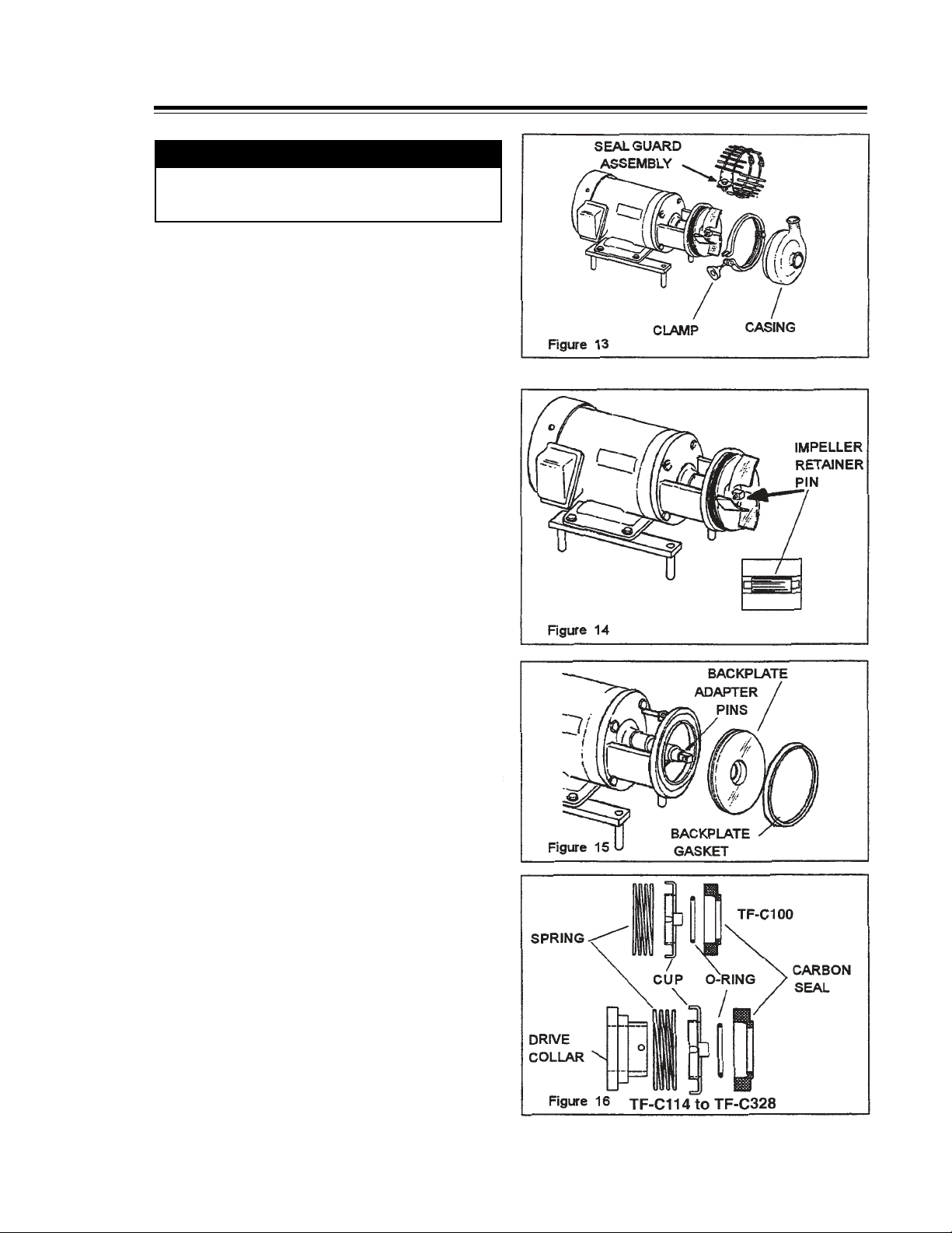
4. Remove the seal guard assembly with a
wrench. (Figure 13)
5. Loosen clamp wing nut and swing clamp
open. On the TF-C100, remove casing
wing nuts.
6. Inspect clamp saddles and the casing for
damage or wear and replace if necessary.
(Figure 13)
7. Push back on the impeller and position
the retaining pin in the center of the stub
shaft. This will allow the impeller to pull off
the stub shaft. (Figure 14)
8. Rotate the backplate to disengage the
backplate pins from the adapter pins.
Remove the backplate with gasket
attached, by pulling straight off the
adapter. (Figure 15)
9. Remove the backplate gasket and inspect
it for wear and sealing failure.
NOTE: Care must be taken to protect the
sealing face and edges of the backplate
from nicks and scratches.
10. Remove the carbon seal, o-ring, seal cup,
and spring from the stub shaft by pulling
them straight off the shaft. (Figure 16)
11. Carefully inspect the o-ring and the
carbon seal for signs of abrasions, cuts,
or other wear that could cause leakage.
(Figure 16)
NOTE: Replace the carbon seal when
the extension end of the seal is less than
1/32”. (Figure 12)
12. After cleaning, inspect the seal, o-ring,
and gasket and replace if necessary.
DISASSEMBLY FOR CLEANING AND REPAIR
12
REPLACING MOTOR
To replace or service the motor, disassemble
the pump as outlined in DISASSEMBLY steps
1 through 11.
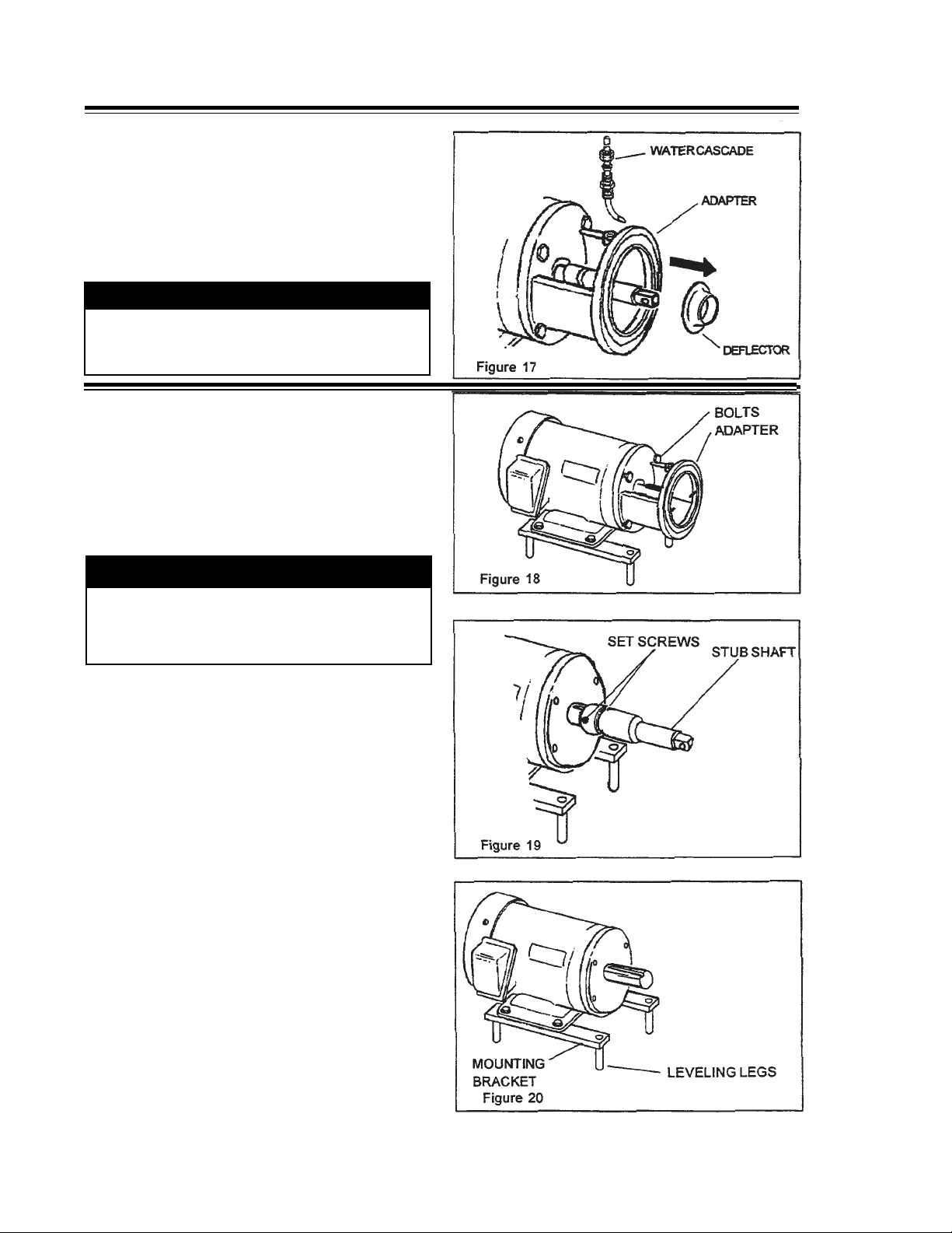
1. Remove the bolts that secure the adapter
to the motor frame and remove the
adapter. (Figure 18)
CAUTION
The stub shaft has four sharp diagonal
grooves in the end. Wear gloves to
prevent injuries to hands.
2. Loosen the two (2) set screws securing
the stub-shaft to the motor shaft.
Carefully remove the stub-shaft. The
stub-shaft is a tight fit, but can be
removed by applying pressure around
the periphery of the shaft with a pry-bar.
(Figure 19)
NOTE: Examine the shaft sealing surfaces for
nicks or scratches which can cause excessive
o-ring wear or leaking.
3. Remove the bolts securing the motor to
the mounting brackets. Bolt the new motor
to the mounting brackets. (Figure 20)
NOTE: Motor maintenance, repair, and wiring
are not covered in this manual. For specific
information contact the motor manufacturer.
If required, level the motor by rotating the
adjustable legs individually. (Figure 3 & 20)
WATER CASCADE - REPLACING MOTORS
MAINTENANCE
13. Remove the water cascade attachment
from the adapter, if included. Remove
the rubber shaft deflector by pulling it
straight off the stub shaft. Examine it for
tearing, loose fit, or other defects that
would allow liquid leakage into the motor
along the shaft. (Figure 17)
WARNING
TO AVOID SERIOUS INJURY, DO NOT
INSTALL OR SERVICE PUMP UNLESS ALL
POWER IS OFF AND LOCKED OUT.

13
n until the impeller pin
1. Mount the adapter to the motor with the
drain cavity at the bottom. Insert the four
bolts to secure the adapter to the motor.
(Figure 21)
2. Install half key in the motor shaft.
3. Place the stub-shaft assembly onto the
motor shaft. Do not tighten the shaft set
screws.
4. Install the backplate on the adapter and
rotate until the backplate pins engage the
adapter pins, assuring solid contact of the
backplate to the adapter. (Figure 21)
5. Rotate the stub shaft until the impeller
retaining hole is in a horizontal position.
Insert the impeller retainer pin, and center
it in the stub-shaft. Slide the impeller on
the shaft. Hold the impeller tight against
the shoulder in the shaft and rotate the
shaft one-quarter turn until the impeller pin
engages with the impeller. (Figure 22)
STUB SHAFT ADJUSTMENT
1. Push the stub-shaft/impeller assembly
toward the motor until the impeller strikes
the front face of the backplate.
2. Move the stub-shaft away from the
motor shaft to allow 1/16-inch maximum
clearance between the rear face of the
impeller and the front (inside) face of the
backplate. (See Figure 22)
3. Tighten the two set screws on the stub-
shaft.
4. Remove the impeller retainer pin, impeller,
and the backplate.
5. Slide the deflector (large diameter end
first) onto the shaft until it seats in the
shaft groove. (Figure 23)
NOTE: If the deflector cannot be forced on
with the fingers, use a blunt tool to tap it
evenly into place.
MAINTENANCE INSTALL ADAPTER-STUB SHAFT ADJUSTMENT
14
T
e drive
2. Assemble the spring, seal cup, o-ring, and
ease, the seal faces will be
. Make
impeller pin, center it in the shaft end, and
es the
d and tighten
in place. Assemble the suction line and the
SEAL CHART for figure 24
MODEL A
TF-C114 9/16”
TF-C216 9/16”
TF-C218 9/16”
TF-C328 9/16”
(Models TF-C114 through TF-C328)
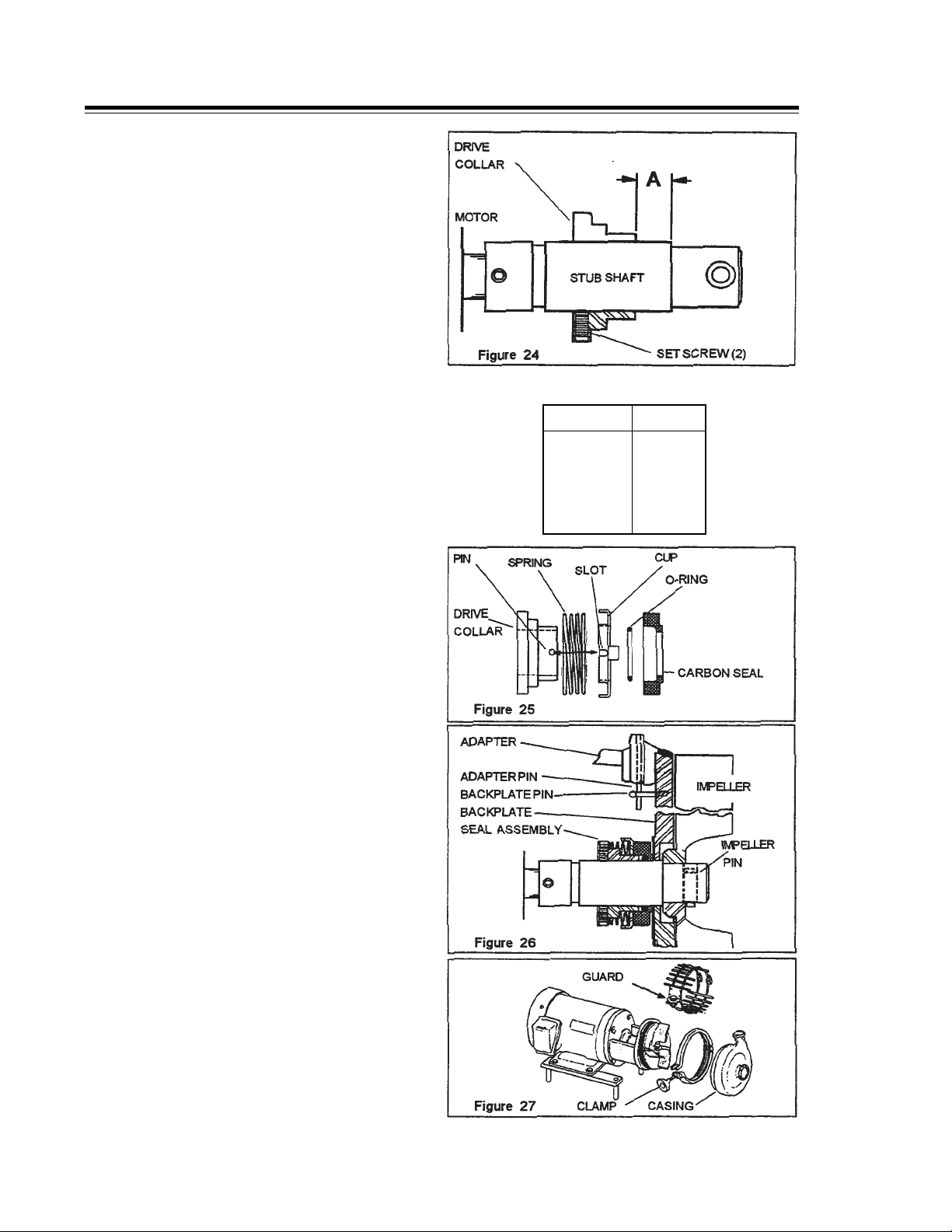
1. Slide the seal drive collar onto the stub
shaft as shown in Figure 24.
Use the “A” dimension in the SEAL CHART
to properly locate the drive collar on the
stub shaft. Tighten the set screws to
secure in place.
NOTE: TF-C100 pump does not require drive
collar.
2. Assemble the spring, seal cup, o-ring, and
carbon seal, and install as a unit. Make
sure the slot in the seal cup aligns with
the pin on the shaft. (Figure 25) Gentle
pressure on the o-ring will overcome
resistance on the shaft.
NOTE: Do not lubricate seals with any
type of oil or grease, the seal faces will be
lubricated by the product being pumped.
3. Assemble the gasket to the backplate.
Install the backplate on the adapter. Make
sure the seal cup slot is engaged with the
pin on the drive collar. (Figure 25)
4. Rotate the backplate until the backplate
pins engage the adapter pins. (Figure 25)
5. Rotate the shaft until the pin hole in the
end is in a horizontal position. Insert the
impeller pin, center it in the shaft end, and
slide the impeller on the shaft.
Hold the impeller tight against the stub
shaft and rotate the shaft one-fourth turn
until the impeller pin drops and secures the
impeller. (Figure 26)
6. Place the casing over the impeller/
backplate, close and tighten the clamp.
(Figure 27)
7. Assemble the cascade water fitting, if
included. Install the seal guard and tighten
in place. Assemble the suction line and the
discharge line to the casing.
NOTE: Check for strain or misalignment
of piping to the casing. Re-adjust the
casing ports and/or entire motor leveling as
necessary.
SEAL CHART for figure 24
MODEL A
TF-C114 9/16”
TF-C216 9/16”
TF-C218 9/16”
TF-C328 9/16”
MAINTENANCE DRIVE COLLAR ADJUSTMENT
15
MAINTENANCE “DG” SEALS
Disassembly
At each step in the disassembly, process parts should be inspected for nicks, cuts,
abrasions, and other wear. Replace parts if necessary. Care should be taken to protect
all sealing surfaces from being damaged during disassembly.
• Disconnect suction and discharge piping from pump casing.
• Remove seal guard and casing.
• Remove the impeller.
• Remove the backplate.
• Remove casing gasket from the backplate.
• Remove the carbon seal, seal cup, and spring from the stub shaft.
• Remove the gland ring, seal seat, and PTFE gaskets by removing the four cap screws.
®
®
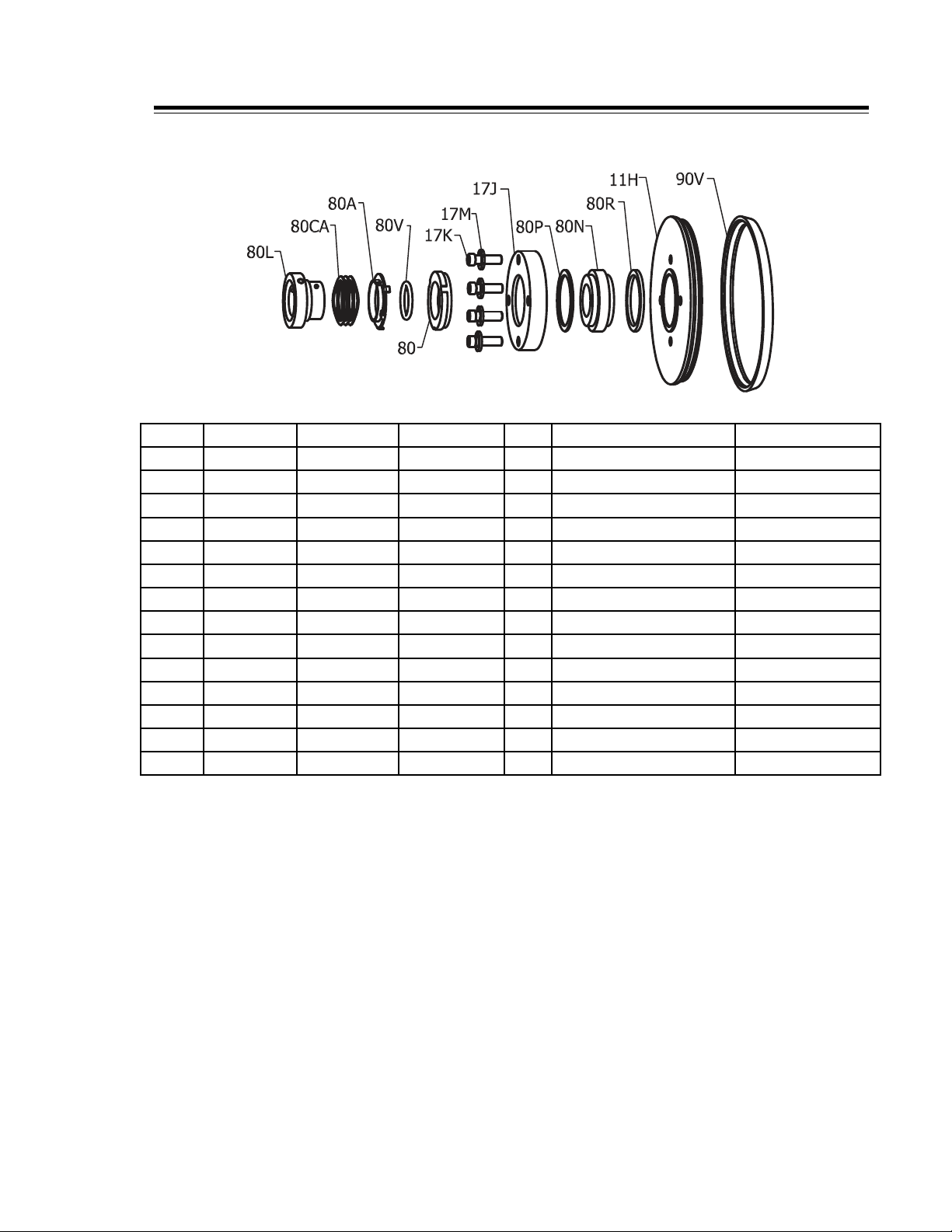
* RECOMMENDED SPARE PARTS SEE KITS PAGE 25
DG-SEAL
KEY C114 C216 C218/C328 QTY. DESCRIPTION MATERIAL
11H 564911H 566911H 568911H 1 BACKPLATE 316L SS
*80R 564980R 566980R 568980R 1 INBOARD GASKET 1/8” PTFE
*80N 564980N-SC 566980N-SC 588980N-SC 1 STATIONARY SEAT SILICONE CARBIDE
*80P 564980P 566980P 568980P 1 OUTBOARD GASKET 1/16” PTFE
17J 564917J 566917J 568917J 1 GLAND RING 304 SS
17K 564917K 568917K 568917K 4 BOLT/SCREW SS
*80 564980 566980 568980 1 ROTATING CARBON SEAL CARBON
*80V 564980V 566980V 568980V 1 O-RING SEAL FKM
80A 564980A 566980A 568980A 1 CUP 304 SS
*80CA 564980CA 566980CA 568980CA 1 SPRING SS
80L 564980L 566980L 568980L 1 DRIVE COLLAR 304 SS
17M WASHER 1/4 WASHER 5/16 WASHER 5/16 4 LOCK WASHER SS
*90V 564990V 566990V 568990V 1 CASING GASKET FKM
*24 564924 566924 568924 1 IMPELLER RETAINER PIN 316L SS
FIGURE 28
* RECOMMENDED SPARE PARTS
16
FIGURE 29
FIGURE 30
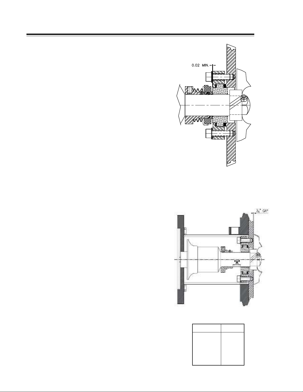
MAINTENANCE “DG” SEALS
Reassembly
Setting the Drive Collar - Measuring Method
1. Assemble the PTFE gaskets, seal seat, gland ring,
and secure to the back plate by uniformly tightening
the capscrews.
Note: The PTFE inboard (80R) and outboard (80P)
gaskets are different thicknesses. The thicker gasket
(80R) must always be installed on the impeller side
to prevent contact between the impeller hub and
the stationary seal.
2. Slide the drive collar onto the stub shaft.
3. Install the backplate and the casing gasket.
4. Install the casing and tighten the casing clamp.
5. Scribe a mark on the stub shaft behind the
backplate.
6. Set the drive collar to “A” dimension in the seal
chart and tighten the drive collar setscrew.
(Figure 30)
7. Remove the casing and backplate.
8. Assemble the spring, seal cup, o-ring, and carbon
seal onto the drive collar. The pin on the drive collar
must align with the slot in the cup.
9. Slide the backplate onto the stub shaft. Position
the impeller retaining pin in the center of the stub
shaft hole and install the impeller. Push the impeller
against the stub shaft and rotate the stub shaft
until the impeller retaining pin falls and secure the
impeller.
10.Check the impeller hub and seal face to ensure
there is a clearance between them before installing
the casing.
11.Reset the seal drive collar if required. When the
drive collar is positioned correctly and the seal
components are properly installed, the shaft should
rotate freely by hand.
12.Assemble the casing gasket, casing, and casing
clamp. Use a soft rubber mallet to line up the
casing. Tighten the casing clamp and install the
seal guard.
SEAL CHART
MODEL A
TF-C114 5/16”
TF-C216 5/16”
TF-C218 5/16”
TF-C328 5/16”

17
MAINTENANCE “DG” SEALS
1. Assemble the spring, seal cup, o-ring seal,
and carbon seal onto the drive collar. Care
must be taken so that the spring does not
rest on the tab that is bent back. A portion
of the spring is offset to provide clearance
for this tab. Care must be taken to ensure
the pin on drive drive collar is in line with
slot on cup.
2. Install as a unit on the shaft.
3. Install the backplate and casing.
4. Install and tighten the casing clamp.
5. Slide the drive collar and seal assembly
toward the backplate until the nose of the
drive collar pushes the o-ring and carbon
seal tight against the backplate.
6. Slide the drive collar away from the
backplace 1/32” (.79mm) and secure the
drive collar in this location with the set
screws.
7. When the drive collar is properly
positioned and the seal components are
properly installed, the pump shaft should
rotate freely by hand. If excessive effort
is required to rotate the shaft, check to
be sure that all components are properly
installed and the drive collar is properly
positioned.
Note: Extra care should be taken when assembling “TF-C”
series pumps with type “DG” or “F” seals. Incorrect
stub shaft settings will allow the impeller hub to
contact the inboard face of the stationary seal seat.
Interference of impeller hub and seal seat face will
cause wear of impeller hub and damage the inboard
or secondary seal face of the clamped-in-seat.
Visual inspection is recommended after installation
of the impeller and before installation of casing to
ensure clearance between the impeller hub and
seal face. If no clearance is visible, the pump should
be disassembled and stub shaft moved forward to
provide at least 1/32” (.79mm) clearance between
the impeller hub and seal seat face. Reset seal drive
collar if necessary.
Setting the Drive Collar – By Position for both “D” Seal & “DG” Seal

18
E-SEAL
KEY C114 C216 C218/C328 QTY. DESCRIPTION MATERIAL
17A CSHH1 566917A 568917A 4 BOLT/SCREW SS
17C WASHER 1/4 WASHER 5/16 WASHER 5/16 4 LOCKWASHER SS
17 564917 566917 568917 1 FOLLOWER 316L SS
*17B 564917B 566917B 568917B 1 O-RING FKM
83C 564983C 566983C-1 568983C 1 STUFFING BOX 316L SS
*83E 564983E 566983E 568983E 1 O-RING FKM
*80H 564980H 566980H 568980H 1 SPRING SS
80J 564980J 566980J 568980J 1 DRIVE COLLAR 304 SS
*80G 564980G 566980G 568980G 2 CUP 304 SS
*80V 564980V 566980V 568980V 2 O-RING FKM
*80 564980 566980 568980 2 CARBON SEAL CARBON
83D 564983D CSHH1 568983D 4 BOLT/SCREW 316L SS
11B 564911B 566911B 568911B 1 BACKPLATE 316L SS
*90V 564990V 566990V 568990V 1 CASING GASKET FKM
MAINTENANCE “E” SEALS
“E” water-cooled balanced double seal consists of two carbon seals inside a stuffing box attached to
the backplate. It is designed for applications where a vacuum-tight, cool operating seal is required.
FIGURE 31
FIGURE 31
* RECOMMENDED SPARE PARTS
Disassembly
At each step in the disassembly, process parts should be inspected for nicks,
cuts, abrasions, and other wear. Replace parts if necessary. Care should be
taken to protect all sealing surfaces from being damaged during disassembly.
• Disconnect suction and discharge piping from pump casing.
• Remove seal guard, casing, and impeller.
• Remove the 4 screws (17A) that retain the follower to the stuffing box.
• Remove the backplate and stuffing box.
• Remove the inboard carbon seal, seal cup, and seal spring.
• Remove the drive collar.
• Remove the carbon seal, seal o-ring, cup, and follower.
This manual suits for next models
5
Table of contents
Other Topline Water Pump manuals


