TopNotch Products SPUNKY User manual

SPUNKY
ASSEMBLY MANUAL

Please read the tips section at the back of this manual regarding the
use of laser cut parts. The proper removal and preparation of these
parts is important. When laser cut, some materials may exhibit some
charring of the edges. This is especially so on composite materials
such as plywood. When gluing these parts at the laser cut edge it is
important to use the correct adhesive. It is recommended that you
use only medium or thick Cyanoacrylate (CA), Aliphatic resin or
Epoxy on these joints. Use of thin CA may not give you a strong
bond. The thin CA may only penetrate the thin layer of charred ma-
terial before it sets, yielding a weak bond. Thick and medium CA,
Aliphatic Resin and Epoxy will allow time for the adhesive to pen-
etrate the char and bond to the material for a stronger joint.

p
Step 1
Glue a strip of 3/8” triangle stock along
the top edge of both fuselage sides
on the labeled side. Be sure to align
the stock with the recessed edge as
shown. Also add triangle stock to the
bottom fuselage edge for and aft of the
wing opening. Note the markings on the
fuselage, they indicate where to stop the
triangle stock.
p
Step 2
Mark the back side of a piece of triangle
stock as shown and cut it on these lines.
Then ip the triangle stock around and
glue it onto the fuselage aligned with the
notches in the front edge of the fuselage,
see the photo in step 3.
p
Step 3
The fuselage sides should look like this.
The triangle stock at the front of the
fuselage will support the motor mount
when installed. Note that the triangle
stock is aligned with the notches, not the
end of the fuselage.
p
Step 4
Assemble F-2 and F-2A as shown, use
a 1/4” drill bit shank to assure the dowel
holes line up with each other and the
two parts are aligned along the opening
in the center. Do not use a wood dowel
to do this as it may become permanently
glued. Also glue two pieces of 1/8” x
1/4” spruce to the top of the servo plate
along the screw holes, this will provide a better grip for the servo mounting
screws.
1
p
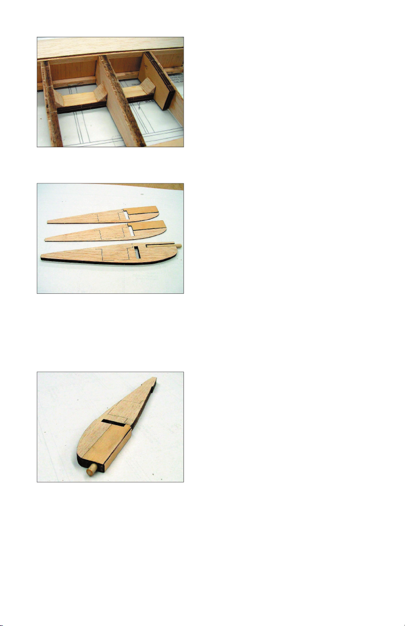
Step 5
Lay one fuselage side at on the bench.
Install F-2, F-3 and the servo plate into
their perspective notches. Assure that
the triangle stock does not interfere with
the parts making good contact with the
fuselage. If so trim it back until contact is
assured. All former labels must face the
front of the fuselage.
p
Step 6
When correct t is obtained, glue all
three parts to the bottom fuselage half
using the top fuselage half to apply
pressure. Then ip the assembly over
and glue all three parts to the other side.
Run a bead of medium CA along all
joints for added strength.
p
Step 7
Measure 2-1/2” from the fuselage end
and mark the inside of the triangle
stock. Then draw a line from that mark
to intersect with the fuselage side as
shown. Remove the triangle stock
along this line as shown to allow the tail
section to come together. Install F-4 but
do not glue it yet. Carefully align the tail
sections and glue them together.
p
Step 8
Install four #4-40 blind nuts into four of
the 1/16” ply pads and then glue these
assemblies to the back of the rewall in
the motor mount holes. The labeling is
on the front of the rewall.
2
p
Step 9
Use Epoxy to install the rewall onto the
fuselage. Use masking tape to assure
good contact between all parts. Note
that 1-1/2° of right thrust is built into the
rewall.
p
Step 10
Test t the fuselage top and then use
an adhesive that will give you time to
pull the top and sides snugly together
and hold it there with masking tape until
cured, such as aliphatic resin. Now glue
F-4 permanently into position.
p
Step 11
Glue on the 1/8” Balsa wing saddle
doublers and then snap the wing mount
plates temporarily into position. Draw
a line along the fuselage side onto the
wing mount plates.
p
Step 12
Trim the anges of two #1/4-20 blind nuts
to the line as shown and install them into
the wing mount plates. Be sure to make
one left and one right. Then Epoxy these
plates into the fuselage sides with the
blind nut anges facing the top of the
fuselage.
3
p
Step 13
Epoxy the wing mount plate braces in
place as shown. Then ip the assembly
over and add a 1-1/4” piece of triangle
stock gusset to the top of each wing
mount plate. You can access this
through the holes in the fuselage top.
p
Step 14
Assemble the 1/8” bottom sheeting for
the tail section and the 1/4” sheeting
for the forward bottom section and glue
in place. Now is the best time to sand
all sides of the basic fuselage smooth.
Sand all corner radius’s at this time as
well.
p
Step 15
Assemble the top deck plate and
formers, D-1 through D-4 and the top
deck keel in place in the fuselage top.
Glue this assembly in place.
p
Step 16
Glue the top deck cap strip on and trim
the edges to the contour of the formers.
Install the 1/16” side sheeting by gluing
along the deck plate at the fuselage top
rst. Then lay it over and glue it along
the cap strip. You can glue it to formers
D-1 through D-4 through the openings in
the top from the bottom of the fuselage.
4
p
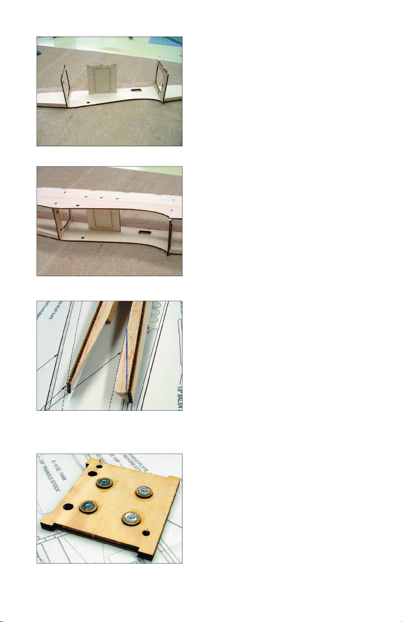
Step 17
Trim and sand the top deck to shape as
shown and then add the cockpit oor.
Angle sand the cockpit oor as shown
to accept the windshield later. The basic
fuselage structure is now complete.
p
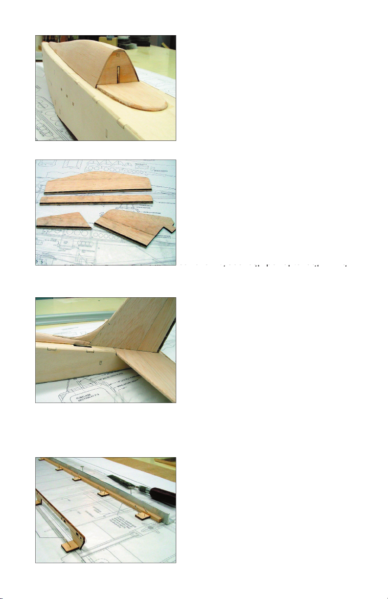
Step 20
With the wing plan on the building board,
align a straight edge with the leading
edge of the spar and secure it there with
pins. Now butt the 1/4” Square balsa
spar up against it and glue a pinning
tab to the back of the spar. Pin this tab
securely to the building board. Place
one of these tabs at every other bay.
5
p
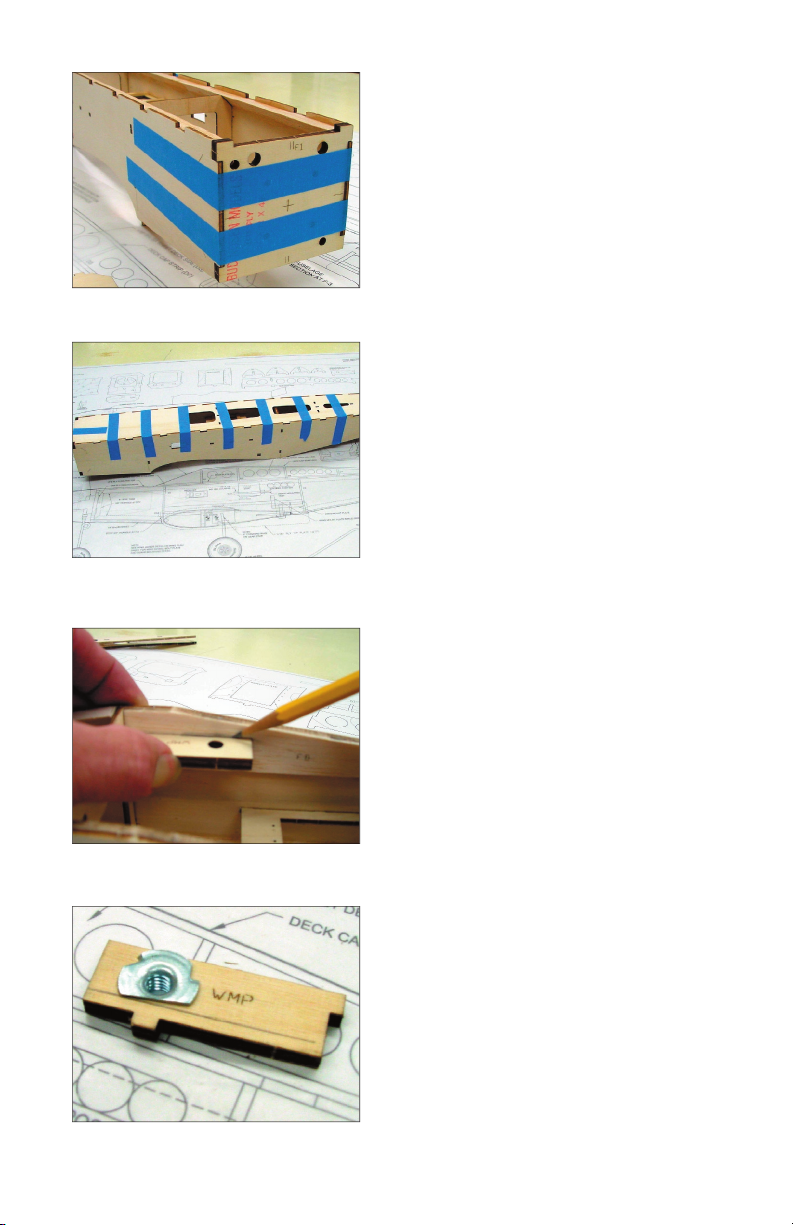
Step 18
Glue the stabilizer sections A & B and
the stabilizer trailing edge together. Glue
the elevator and elevator trailing edge
together. Glue the vertical n sections
A & B together and then glue on the
vertical n trailing edge. Glue the rudder
and rudder leading edge together and
sand all these components out. When
assembling the n and stabilizer components, use the marks on the parts
sand all these components out. When
assembling the n and stabilizer components, use the marks on the parts
sand all these components out. When
assembling the n and stabilizer components, use the marks on the parts
assembling the n and stabilizer components, use the marks on the parts
assembling the n and stabilizer components, use the marks on the parts
for alignment.
p
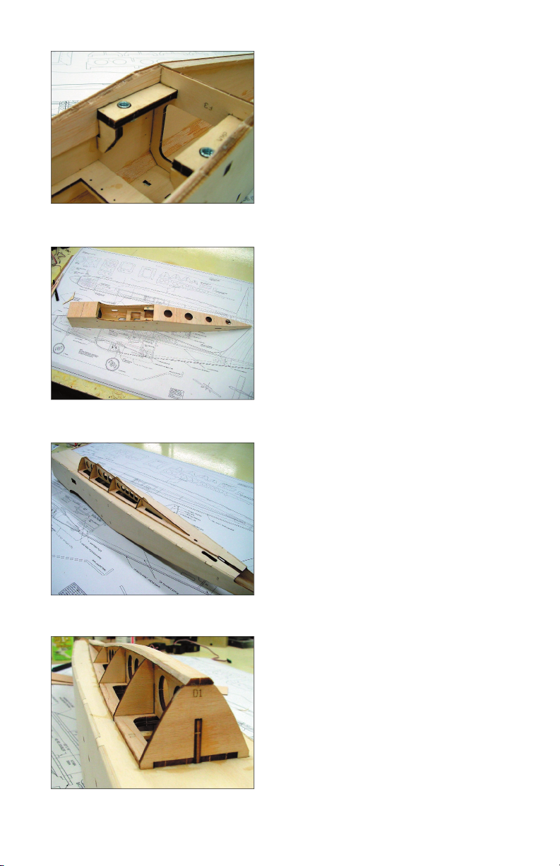
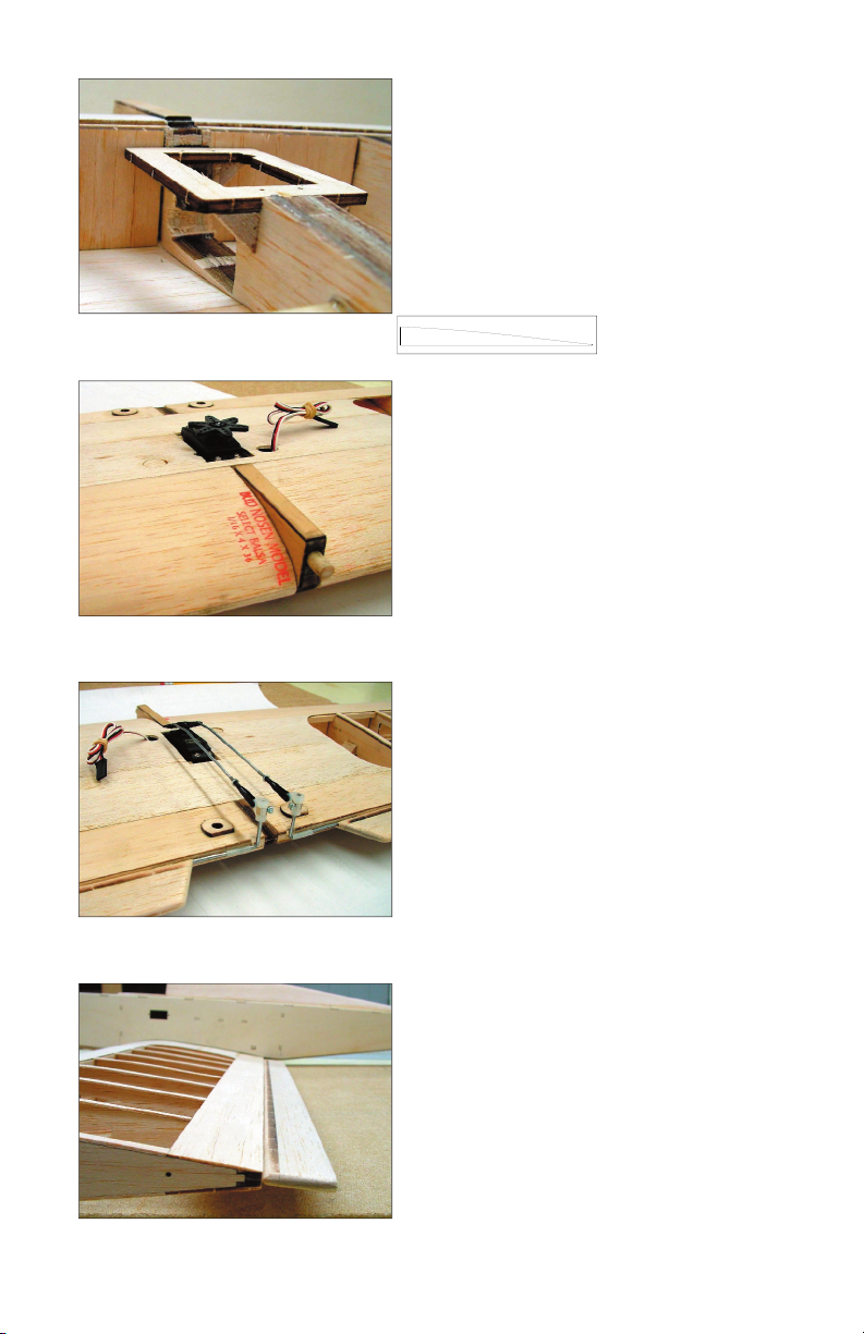
Step 19
Use the center line marked on the
stabilizer assembly to align the stabilizer
on the stabilizer saddle. Butt the stabilizer
up against the fuselage top. Check that it
is perfectly horizontal when the fuselage
is setting at on the bench and then glue
it on. Install the vertical n, check that
the trailing edge splits the center line
on the stabilizer and then glue in position. Use a generous application of
adhesive on the stub that butts up against F-4 inside the fuselage. You can
access this joint through the hole in the bottom sheeting.

Add pinning tabs to the break away feet on the false trailing edge and also
pin these rmly to the building board. Note that the 1-1/2° washout is set
by the false trailing edge. Be sure that the break away feet are at to the
building board while assembling.
6
p
Step 21
Assemble W-2, GB and GBC. Assemble
W-3 and W-3B. Assemble one W-4 and
W-4B. To assure a left and a right wing
set, assemble these components for
both wings at the same time. Making
sure to construct mirrored sets. That
way you can not go wrong. Also take
care to align the parts with each other.
p
Step 23
Glue the leading edge in place at W-1
and W-5. Then adjust each rib to seat
in the slots in the leading edge and glue
them. Now glue the ribs to the bottom
spar. When gluing W-1 and W-2, only
glue to the sides of the spar, not the
top.
p
Step 22
Glue sheer web SW-1 to the bottom spar
observe the correct orientation of the
dihedral angle. Align it to the line for W2
on the plan. Install W1 using SW-1 to set
the dihedral angle. Install WBP and the
W2 assembly. Proceed down the false
trailing edge installing the remaining ribs
and glue them to the false trailing edge
only at this time.

p
Step 24
Carefully remove the material between
the top and bottom spar notches at W-
1 and W-2. The spar opening has been
laser cut but a small amount of material
will have to cut to make this opening.
p
Step 25
Install the top spar and use the spacers
provided when gluing to W-1 and W-2.
Apply a bead of medium CA to all wing
joints at this time.
p
Step 26
Add the 3/32” sheer webbing the full
length of the wing at the front of the spar.
Add 3/32” sheer webbing between W-1,
W-2 and between W-2, W-3 to the back
of the spar. This will form the spar box.
p
Step 27
Install the 1/4” wing bolt seat onto the
wing bolt plate. You will also add one
of these to the bottom of the wing later,
do not shape these to the contour of the
wing. They will provide a perfectly at
surface at 90° to the bolt orientation for
seating the wing mounting bolt.
7

p
Step 28
Glue on the laser cut 1/4” trailing edge,
make sure the laser cut hinge slots are
facing aft and the root and tip are oriented
correctly. The root has a larger slot cut
for the aileron linkage installation. Sand
the trailing edge and false trailing edge
to the contour of the wing and then add
the 1/16” balsa trailing edge sheeting.
p
Step 29
Mark the exact center of the top spar and
insert a pin at each end at that location.
Use medium CA to glue the leading
edge sheeting along the entire length of
the top spar using the pins to align it. Do
not apply any glue to the ribs at this time.
We will do that in the next step.
p
Step 30
Remove the wing assembly from the
building board and snap off the pinning
tabs and breakaway feet on the false
trailing edge. Starting at the center of
the wing lay the leading edge sheeting
against the ribs and glue it. Lay the
sheeting at on the leading edge and
glue it in that position. When nished,
trim off the excess sheeting ush with the leading edge. Turn the wing
assembly over and repeat steps 28, and 29. When installing the bottom
leading edge sheeting apply aliphatic resin glue to the each rib from the
spar to the leading edge, but not the leading edge. Use medium CA to glue
the sheeting to the main spar and then proceed by pulling the sheeting
at against the leading edge and gluing with CA as you did on the top
sheeting. When nished the leading edge should look like the photo.
Put this wing half aside and repeat steps 20 through 30 for the remaining
wing half.
8
p
Step 31
Assemble the 1/4” ply main gear mount
and the 1/8” ply main gear mount retainer
plate. The end of the slot in the retainer
plate aligns with the hole in the main
gear plate. Install this assembly into the
notches provided in WGB, W3-B and W-
4-B. The end of the assembly with the
hole in it should be pointing toward the
p
Step 32
When assembling the wing joiner, use a
generous amount of Epoxy to install the
wing dowel and the wing dowel cap. Use
adhesive sparingly around the servo
knockout cuts.
The wing joiner is assembled from six
parts, they are the 1/4” core, two 1/16”
balsa sides, two 1/16” ply sides and a 2-
1/2”x 1/4” dowel. This assembly performs
several functions, in addition to aligning
the wing incidences it provides a secure
elevated mount for the wing dowel and
also serves to support the aileron servo.
A knockout for the aileron servo opening has been cut into all the required
parts. When assembling the wing joiner, do not allow adhesive to get into
the knockout cuts. If you do they will be dif cult to remove. You can use
thin CA to rm up all these parts after the knockout has been removed.
NOTE:
root of the wing. Add some triangle stock gussets to the top of the landing
gear block a shown.
9

p
Step 33
Assembly sequence of the wing joiner.
Apply Epoxy in the spar box, on the
spar, to the joiner and ribs forward of the
spar and to the joiner and ribs at least 1”
behind the servo knockout. Make sure
both wing halves align at the trailing
edge and secure in that position with
pins until cured. Long strips of masking
p
Step 34
Install the forward bottom center section
sheeting next. In this photo, the openings
for the landing gear blocks have not
been cut, They are now laser cut into the
bottom forward center section sheeting
and it need only be placed in position
and glued.
p
Step 35
The top and bottom center section
sheeting has been cut slightly oversized
to accommodate variations in positioning
of the leading and trailing edge sheets
by the builder. Butt the back sheet up
against the trailing edge sheeting and
mark where they overlap, trim and
install.
p
Step 36
Trim the retainer tabs on the servo
knockout and remove the material at the
center of the wing joiner. This works best
if you remove the material one layer at
a time. After removal, harden this area
with some thin CA.
tape pulled taught along the leading and trailing edge sheeting work great
for pulling the wing halves together.
10
p
Step 37
Glue the aileron servo tray into position
and brace it with some triangle stock
gussets as shown. NOTE: Not shown
here, install the two sheet support rib
sections to the top of the servo tray
along both sides of the servo opening.
These supports look like the drawing
below.
p
Step 38
Install the top sheeting and then
temporarily install the aileron servo.
The top sheeting has holes cut into it for
the servo and the servo cable exit. You
will need to enlarge the servo hole to
accommodate your servo.
p
Step 39
Assemble the ailerons and aileron
leading edges, sand to shape and then
test install the hinges and the aileron
linkage. The aileron horn bearing will
need to be trimmed some to avoid hitting
the wing bolt plate. Then Epoxy in place.
NOTE: All hinge slots are laser cut but
you will need to increase the depth of
these slots by about 1/8”.
p
Step 40
Aileron installation should be straight
and tight. Allow only a minimum gap
between the wing and the aileron for
smoothest aileron effect. Permanently
attach only after covering.
11
p
Step 41
Du-Bro steel landing gear straps are
used to retain the landing gear leg.
p
Step 42
When opening up the cowl, give the
motor plenty of space for cooling air.
This is a berglass cowl fabricated
for the prototype model. Install the
mounting screws so they screw into
the 1/4” ply rewall and then harden the
holes with CA.
p
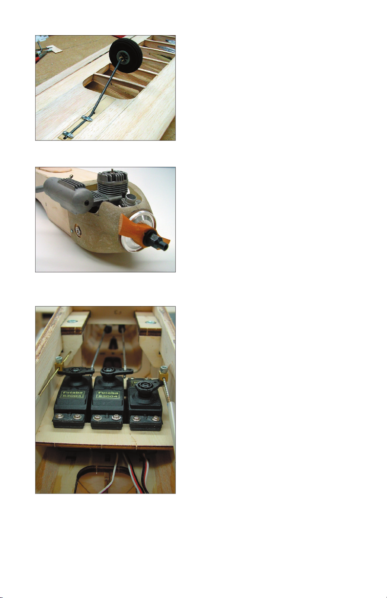
Step 43
Installation of the servo’s. Note that the
center push rods utilize a Z-bend to
maintain a low pro le to allow space for
the aileron servo. Make sure all linkages
are snug with no play. Note that a small
amount of material was removed from
the fuselage doubler to allow clearance
for the throttle linkage connector block.
Temporarily install all linkages, the motor
and the fuel system before covering. You
may have to remove a small amount of
material at the corner of the rewall for
muf er clearance depending on your
choice of motor.
12
Other TopNotch Products Toy manuals

TopNotch Products
TopNotch Products MINI SUPREME User manual

TopNotch Products
TopNotch Products Seamaster II User manual

TopNotch Products
TopNotch Products Mooney M-18 User manual

TopNotch Products
TopNotch Products Li'l Pup User manual

TopNotch Products
TopNotch Products Maverick User manual

TopNotch Products
TopNotch Products BUSH HAWK XP User manual


