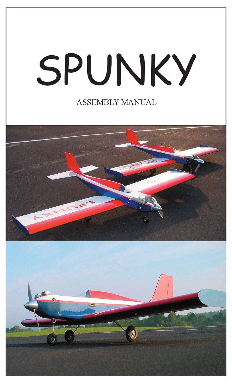
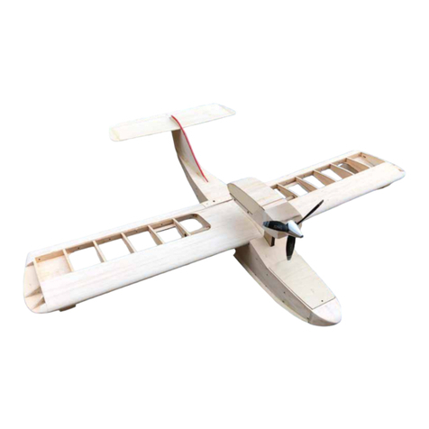
TopNotch Products Mooney M-18 User manual

TOP NOTCH
Mooney M-18
Mooney Mite
ASSEMBLY MANUAL
Top Notch Products Company
PO Box 1051
Goodlettsville, TN 37072
Made in the USA

BEFORE YOU BEGIN
A word about laser cut parts and adhesives.
There are three primary types of adhesives recommended for constructing your model. They are CyanoAcrilate
(CA) in all viscosities, Aliphatic Resin Glue (carpenters glue) and Epoxy. CA is the primary adhesive to use
however there are times when it is not the best choice. They are:
When you need more time to carefully position a part than a fast setting adhesive will allow.1.
When attaching plastic such as a windshield (Use Pacer formula 560 here).2.
When gluing laser cut aircraft grade plywoods. The microwave set adhesives used in aircraft grade plywoods3.
ablates at a much higher temperature then the surrounding wood. As a result it burns the wood bers near by
leaving a thin charred edge. Fast setting CA adhesives do not allow time for the adhesive to penetrate this layer of
char and bond to the wood ber underneath. Use a slower setting adhesive such as Aliphatic Resin or for maximum
strength use Epoxy on aircraft grade ply parts. Lite Ply’s do not use this type of adhesive and do not suffer from
this problem.
To apply thin CA I recommend the Dave Brown pipets available at your hobby shop. Be sure to stretch the end
(pull it with a pair of pliers) to a thin applicator tip, as they are not supplied in this conguration and some folks
don’t know that you have to do this. No mention of this is made on the package they come in.
PIN REGISTRATION
A great shop technique introduced by Top Notch Products is the use of 1/8” piano wire pins to quickly and precisely
position laminated parts such as fuselage doublers etc. Many of the parts in Top Notch kits utilize this method
and are supplied with pinning holes. Take the time to construct two of these handy tools. Use two small hardwood
blocks and two short lengths of 1/8” music wire. Round the ends for easy insertion into the parts.
Below are two examples of this technique as used in the Cessna 195 kit. On the left, two re wall com ponents are
being assembled using the pins. Any time precision placement is required, this method is used. You will nd the
pinning holes are easily lled after completing the model. This method allows the use of fast setting adhesives such
as CA because the parts cannot be out of register. In the photo on the right, landing gear components are being
assembled with the pins. Precision placement of these parts is required to assure that the 1/8” landing gear wire will
t snugly into this assembly. In the background is the completed re wall assembly.
Use a sheet of Wax Paper to protect your plans. When assembling at sheets such as the stabilizer skins I recommend
laying the parts on a sheet of parchment paper. Assemble the parts, apply thin CA and frequently lift the part and
wipe up any excess CA from both the part and the paper with a piece of paper towel.
1
OK, LETS BUILD A TOPNOTCH MOONEY M-18

The vertical n and rudder assembly will employ most of the building techniques used in the rest of the aircraft so
we will start with these smaller parts. Note that I will go into detail on this assembly but will only refer to these
methods later on for the remaining assemblies. Even if you decide to build the model in a different sequence then
arranged here in the assembly manual, It would be wise to build the n and rudder assembly rst if only for this
reason.
Mooney M-18 Assembly Instructions
The stabilizer, vertical n and ailerons of the Mooney utilize core sheet construction. If you are not familiar with
this method of construction you will be pleased with the speed and ease of construction. In addition, this type
of structure is very light and very strong and conforms perfectly to the scale airfoil of the full-scale aircraft. You
will be building each structure onto a 1/16” balsa sheet cut with notches for all ribs, leading and trailing edges. It
is important to make sure that these assemblies are held perfectly at during the gluing process. Whatever shape
they possess when they are glued is the shape they will retain so keep them at.
£ 1Locate the vertical n components VC, V1 through V5, VTE, VLE and VT. Note that the tabs on the ribs
are longer at the trailing edge of the ribs then they are at the leading edge. The Mooney has a 29° forward
sweep of the trailing edge and that can be confusing while in the building process.
£ 2Install V1 into the appropriate notches
in the core sheet VC. Observe the cor-
rect size notches, the narrower end is
the leading edge. Hold V1 rmly at
against VC when applying glue, thin
CA is recommended.
£ 3Proceed to install and glue V2 through
V5 in the same manner.
£ 4Note that the trailing edge of VC has
notches for the trailing edge section
VTE. Be sure that VTE is seated in
these notches and then apply thin CA
while holding the assembly at against
the building board. Assembly of the vertical n underway with only one side completed. Note
the core sheet splice on the right. The tabs on the trailing edge will position
the sheeting when installed. The hinge pin openings have been capped with
balsa and the assembly is ready to be turned over and completed.
£ 5The leading edge has no tabs and is very
thin but it is installed in the same
manner. Use the edge of a straight edge to hold VLE rmly against VC while applying glue.
£ 6Install the hinge caps VHC at each hinge location. Note that each hinge cap is a different shape to accom-
modate that particular location. These caps will provide a pocket for the Robart hinges.
£ 7Flip the assembly over and repeat this process on the opposite side. V1 through V5, VTE, VLE and three
hinge caps VHC.
£ 8The Vertical Fin sheeting is supplied in two pieces that must be assembled before sheeting the n. Locate
and assemble VS. Select the best side for the outside and sand smooth while still at. Note the two notches
in VS will engage the two tabs on VTE to precisely position the sheeting.
2

£ 11
£ 9
3
Glue the sheeting (VS) to the n.
£ 10 Glue on VT to the tip on both sides.
Sand the n to nal shape.
The vertical n sheeting is assembled from two laser cut parts and then
sanded at before installing onto the vertical n assembly.
The vertical n assembly ready for sheeting. Note that all hinge pin open-
ings have been capped and the leading and trailing edges have been sanded
to contour with the ribs. Avoid altering the tabs on the trailing edge when
sanding to contour. They will be sanded after the sheeting is attached.
£ 12 Use a hinge to mark the trailing edge at
the barrel of the hinge. Remove a small
amount of material from the trailing
edge to allow the hinge to be seated with
the pivot point aligned with the trailing
edge. Note that when the hinge bottoms
in the opening provided your hinge line
will be laser straight.
After sheeting, VT pieces are added and sanded
to contour. Note the hinge pin openings are al-
ready provided and will assure a straight hinge
line.
When the hinge pins are bottomed in the hinge
pin holes, they are in the correct alignment. A
small amount of material must be removed to
accommodate the hinge barrel.
Assembly of the vertical n completed and ready for nal sanding and shap-
ing of the leading edge. Very little additional shaping is required to form a
perfect airfoil. Very light, very strong and very quick to build.

4
RUDDER ASSEMBLY
The rudder is composed of three sections that are glued together. The core sheet or center lamination con-
tains openings for the hinges as well as the rudder torque rod. You will use the pin registration method to
assemble these three components.
£ 1Locate and prepare one RC and two
RUD parts. Place one RUD on the reg-
ister pins. I do not recommend CA for
this assembly; instead use an adhesive
that you can spread a thin layer onto the
surface of RC. This can be Aliphatic
Resin or spray on contact cement. You
will want a thin but rmly glued joint
between the three sections when you
go to shape the nal part. Apply a thin
layer of adhesive to the correct side of
RC and then slide it down the pins into
contact with RUD.
One RUD part has been placed on the register pins and the core (RC) has
been coated with spray adhesive and is about to be pushed down the register
pins and into contact with RUD. Note that the rudder core sheet contains the
hinge pin openings precisely aligned with those in the vertical n. Also on
the right is a slot for the rudder torque rod. Note the half moon key at the left
end that will receive the tip assembly.
£ 2Apply a thin layer of adhesive to the re-
maining RUD and slide it down the pins
and into contact with the assembly. Re-
move from the pins and put under pres-
sure until cured.
£ 3The leading edge of the rudder assem-
bly will need to be double beveled to
accommodate the swing of the rudder.
I prefer to do this on a band saw set to
35° angle. Note that this will only work
before shaping the airfoil. Using a razor
plane will work as well.
£ 4Three 1-1/2” pieces of music wire are
used in the hinge pockets to hold the
rudder and vertical n in perfect align-
ment. Then the leading edge of the rud-
der is marked for shaping. On the left is the vertical n assembly with steel pins temporarily replacing
the hinge pins and on the right is the rudder assembly. The double bevel
on the rudder was cut using a band saw set at 35°. The rudder has been
removed from the steel pins after marking the leading edge with the n trail-
ing edge. The rudder assembly can now be tapered to match the n. The
rudder torque rod is only temporarily installed and will be removed before
nishing.
£ 5First plane the rudder down to the thick-
ness indicated by these lines and then
introduce into it the airfoil shape.
£ 6Assemble the two RT pieces and then glue onto the tip of the rudder. Place the assembly back onto the n
using the pins and mark the counter balance (the material that sticks forward of the hinge line) along the
n for a trimming guide. The counter balance should be the same width as the n. Then trim and sand to
contour with the rudder.
Table of contents
Other TopNotch Products Toy manuals

TopNotch Products
TopNotch Products SPUNKY User manual

TopNotch Products
TopNotch Products Seamaster II User manual

TopNotch Products
TopNotch Products BUSH HAWK XP User manual

TopNotch Products
TopNotch Products MINI SUPREME User manual

TopNotch Products
TopNotch Products Li'l Pup User manual

TopNotch Products
TopNotch Products Maverick User manual
Popular Toy manuals by other brands

FUTABA
FUTABA GY470 instruction manual

LEGO
LEGO 41116 manual

Fisher-Price
Fisher-Price ColorMe Flowerz Bouquet Maker P9692 instruction sheet

Little Tikes
Little Tikes LITTLE HANDIWORKER 0920 Assembly instructions

Eduard
Eduard EF-2000 Two-seater exterior Assembly instructions

USA Trains
USA Trains EXTENDED VISION CABOOSE instructions


