Seamaster II Fuselage Assembly
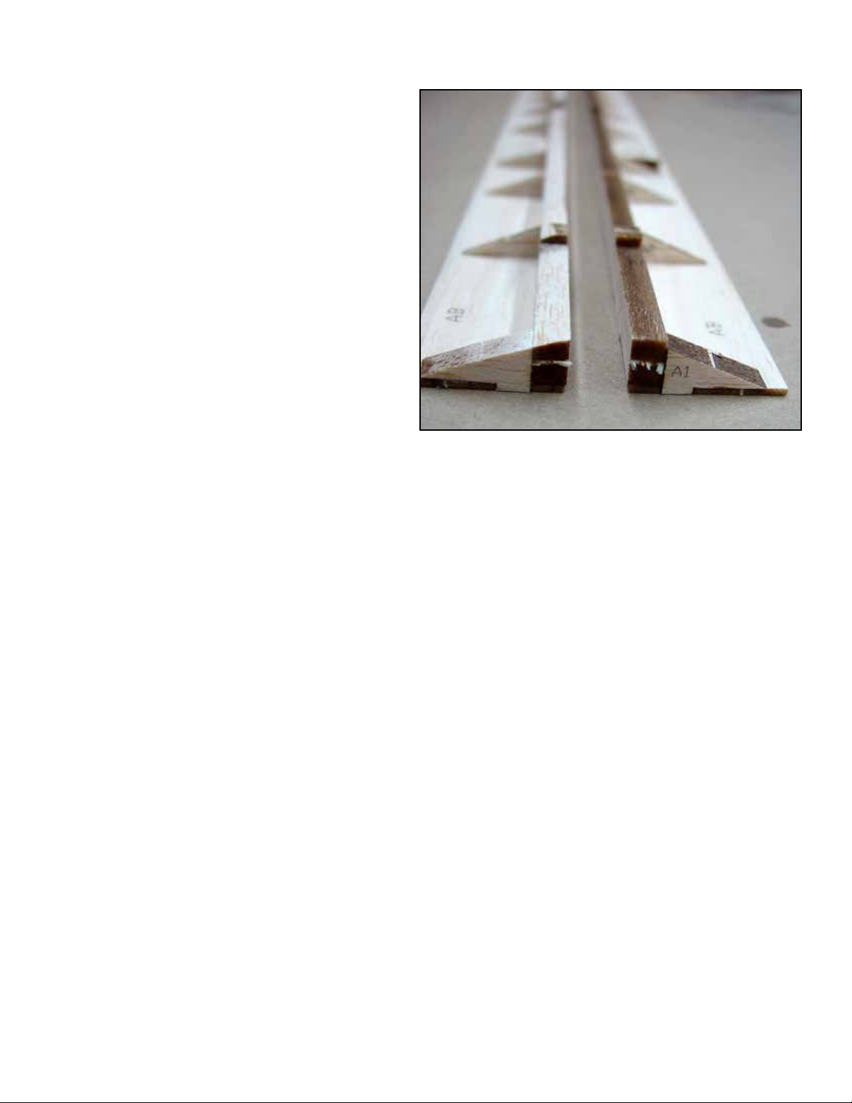
Locate and prepare the two fuselage sides (FS).
Lay them on the workbench with the tops fac-
ing each other (back to back, see photo).
c 1
c 9
c 5
c 4
c 3
c 2Locate and prepare the wing saddle doublers
(WS).
Use the Registration Pins to install and glue it
to the fuselage sides. Note that you will make
a LEFT and a RIGHT fuselage side. See the
photo.
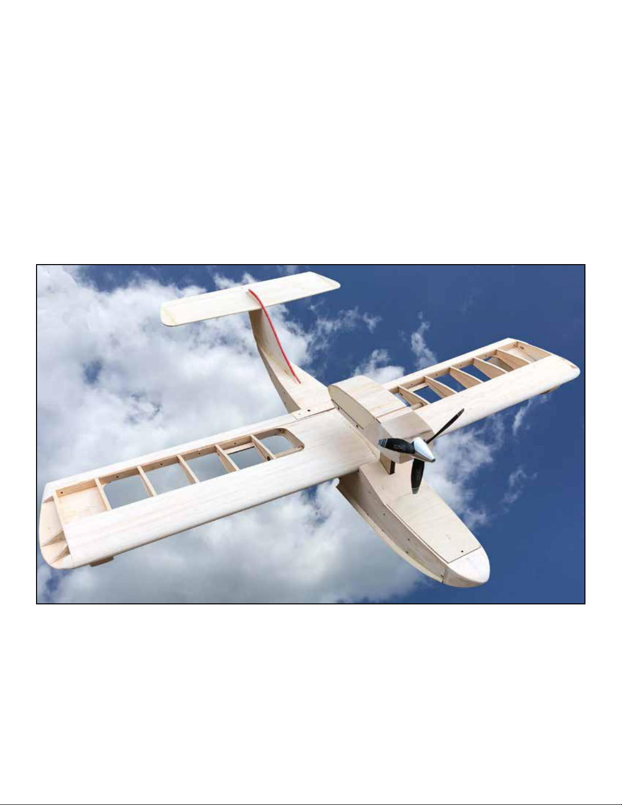
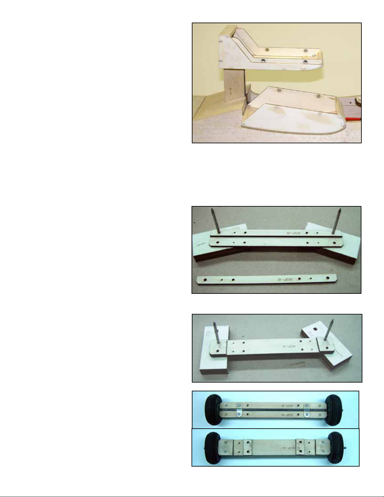
Locate the Fuselage Servo Tray (FST) and two
3/16” x 3/8” x 4” basswood rails. Note that
FST can be congured for standard size servos
(remove the dash cut area) or for micro servos.
Determine which you will be using and cong-
ure it appropriately. Glue the basswood rails to
the edge of the servo opening to provide mate-
rial for the servo screws. Glue them in position.
The left and right fuselage sides are laid out and the wing
saddles are installed using the registration pins.
Now is a good time to mark and drill the pilot
holes for the servo mounting screws.
c 6Install and glue the Fuselage Servo Tray assem-
bly to F5 and F6, note that the servo tray screw
rails should be on the bottom.
c 7Glue the F5 and F6 assembly to the RIGHT
fuselage side.
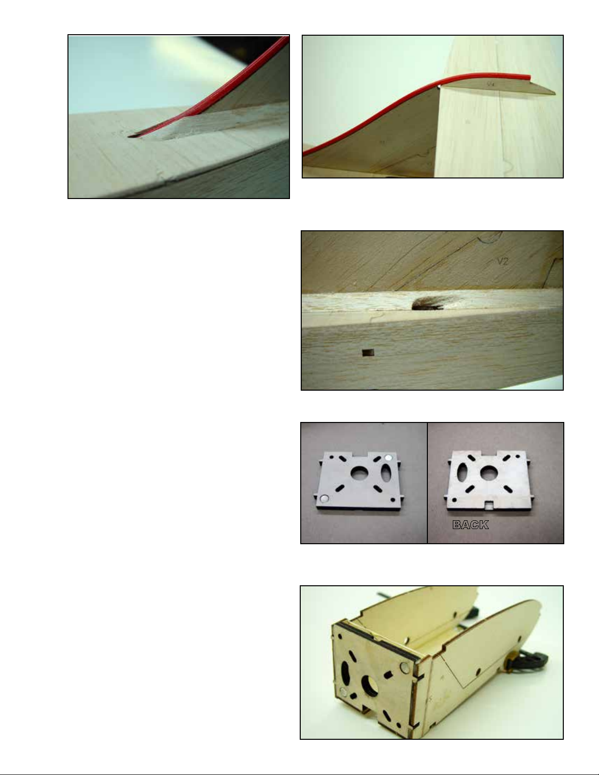
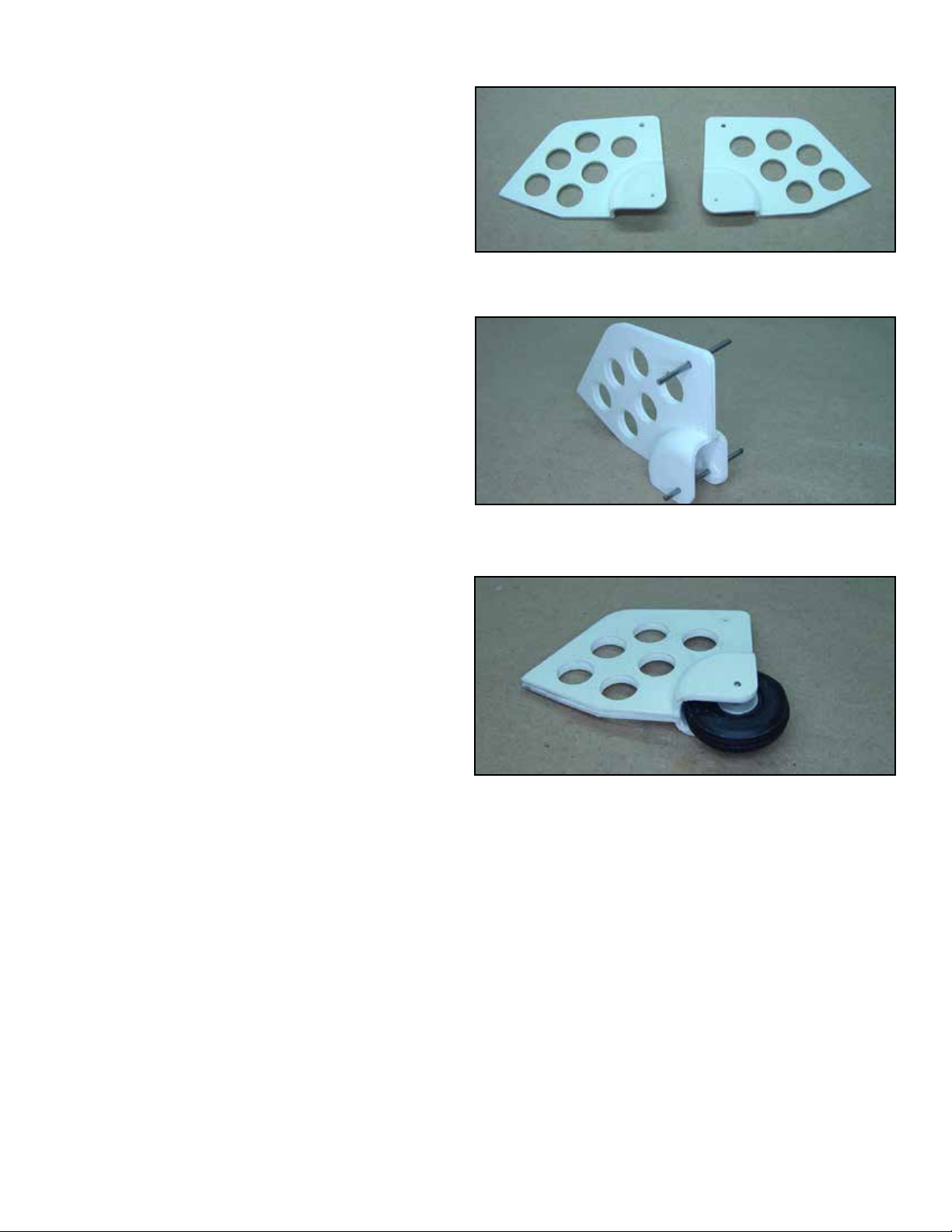
c 8Locate the Wing Mounting Plate and two #10-
32 blind nuts. Press the blind nuts rmly into
the holes provided in WMP.
Because WMP and F8 interlock it is best to
install them at the same time. First install and
glue WMP into the notches in F8 and then glue
this assembly to the fuselage side. Note that the
anges of the blind nuts should be facing down.
ABOVE: The servo tray can be congured to t standard or mini
servos. Remove the dash cut material for standard servos.
BELOW: F5, F6 and the servo tray assembly.
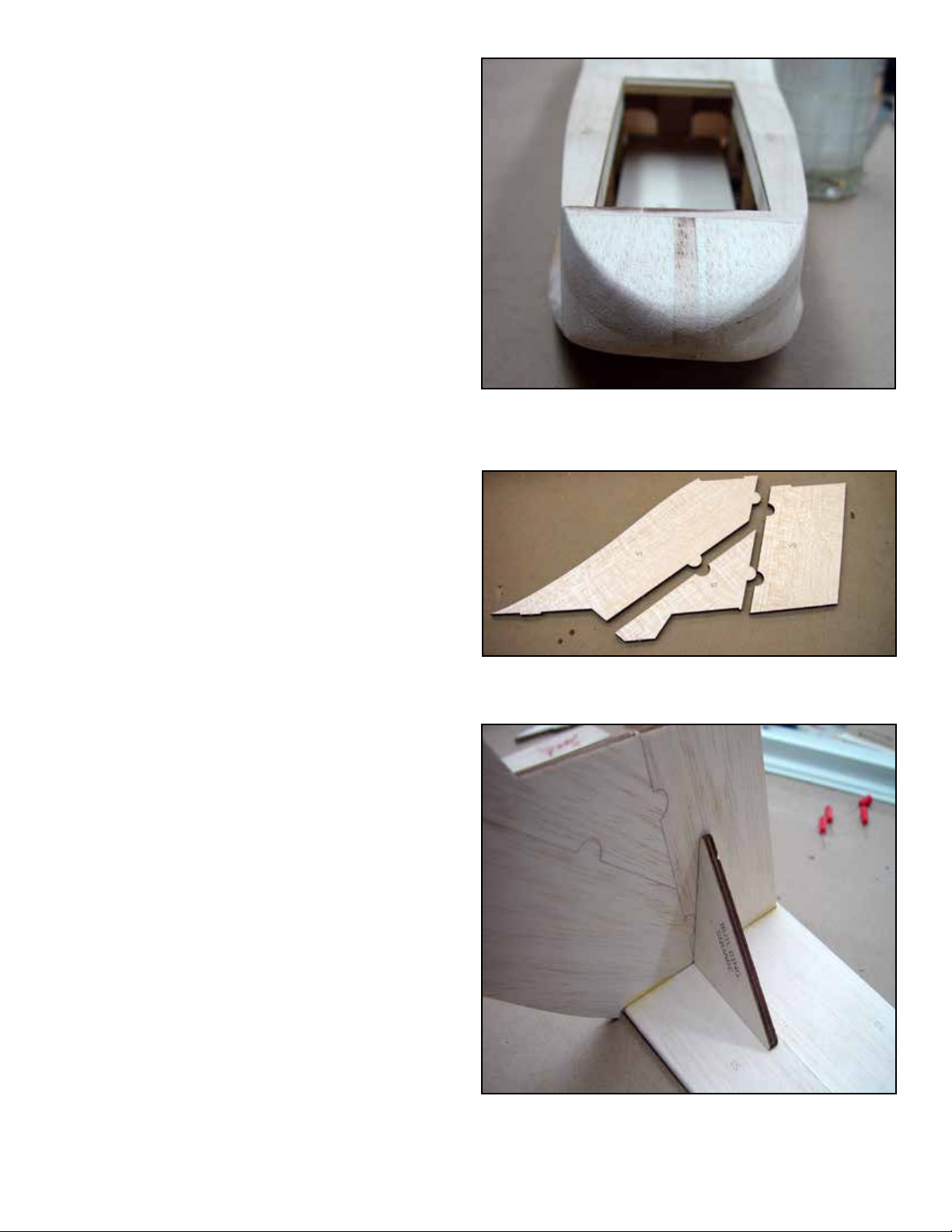
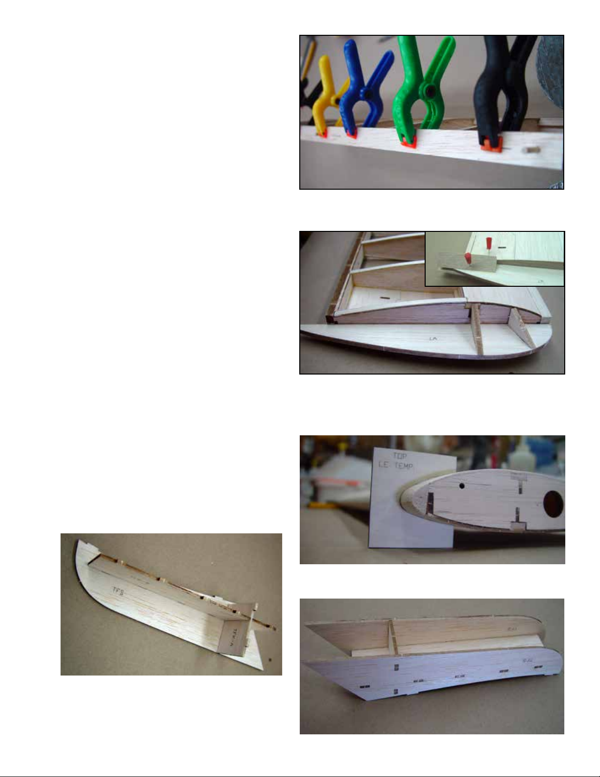
c 10 Test t the le fuselage side to the right fuselage
side assembly. When all notches and tabs are
aligned, apply glue and secure the two halves
together.
Note: Make sure the fuselage assembly is at on the
building bench. Weight the assembly down until the
glue cures to insure a straight fuselage.
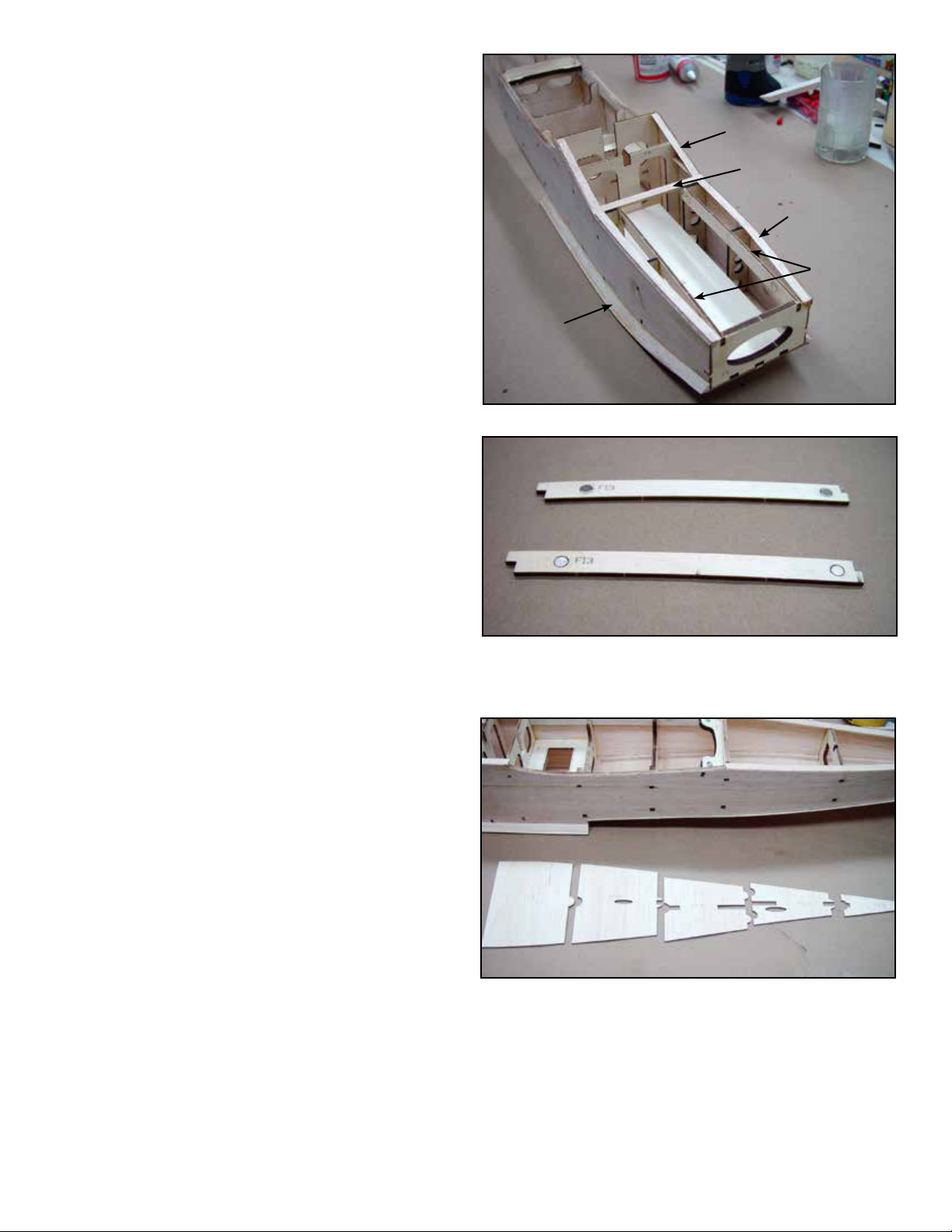
c 11 Locate F1, note the dashed line at the bottom,
and sand the bottom to taper from back to front
down to the dashed line. is will conform to
the curve at the bottom of the fuselage side
when installing the fuselage bottom.
Here only half of the bottom of F1 has been beveled to the dashed
line to accommodate the curved bottom sheeting. Leave the tab
until after the sheeting has been attached.
2