TopNotch Products MINI SUPREME User manual

TOP NOTCH PRODUCTS
MINI
SUPREME
Top Notch Products Company
PO Box 1051
Goodlettsville, TN 37072
Phone 615-866-4327

BEFORE YOU BEGIN
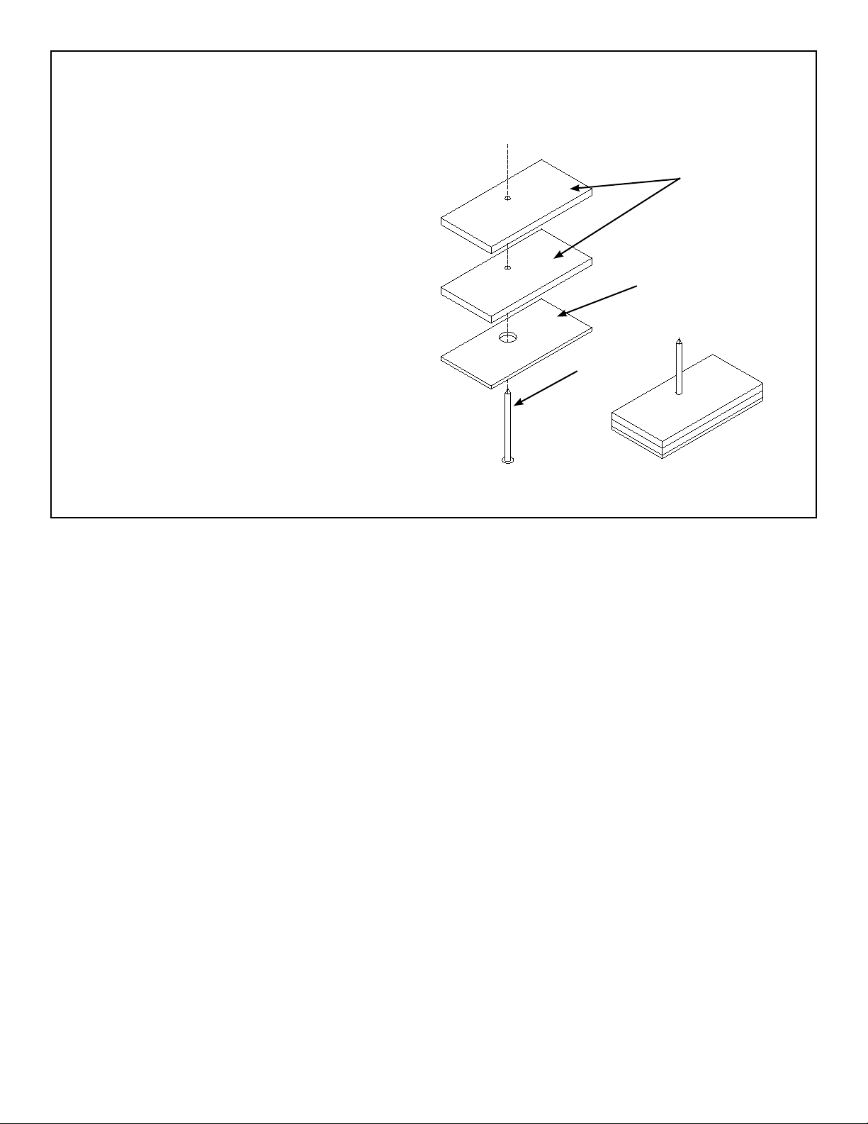
1/4” LPLY (PB)
1/8” LPLY (PB)
8d Nail
Completed pinning block,
two required.
Assemble the registration pinning blocks as
shown at the right. ese will be used through-
out the assembly to insure proper alignment of
parts.
e nail head must be seated below the surface
of the bottom lamination so the block will sit
at on the bench. Use CA or Epoxy to secure the
nail in the block.
If your new to building models, you will need a place to work that can be undisturbed until you complete
the build for best results. I recommend using the back side of a drop in 2” x 4” ceiling tile on your work
bench. This material is soft enough to receive the pins but rm enough to hold your parts securely. They
are available at any home store.
I recommend three types of adhesives, Thin and medium cyan o acrylate known as CA or Super Glue,
aliphatic resin also known as carpenters glue such as Elmer’s or Titebond and Epoxy. Do not use thin
CA on plywood parts.
1

c 1
c 6
c 5
c 4
c 3
c 2
We will begin by building the wing since it will be needed to get the correct lofting of the aft fuselage
section. Place the plan on the building board and cover them with waxed paper or Parchment paper to
protect them from the glue. When a part is called for, refer to the parts locater in the back of this manual
for the sheet number it is on.
. With the wing plan on the building board
and protected with waxed paper, lay a
straight edge over the plans and align it
with the aft edge of the False Leading Edge
(FLE). Secure it there with pins to prevent it
from moving.
Note the standos on FLE, the one with the
line through it is the root end or inboard end.
Align this line with the alignment line noted
on the plans and secure it to the building
board by tack gluing pinning tabs to each
stand o and pinning it to the building board.
Make sure each stando is at on the build-
ing board.
WING ASSEMBLY
The alignment line cut into the rst stando on the root end
must be aligned with the alignment line indicated on the
planes to insure a straight assembly.
Alignment Line
Locate and prepare the spar (SP) by remov-
ing it from the carrier sheet and make sure
all slots are clear. Note the dash cut section
at the root end. Leave that material in place
until directed to remove it. Locate the short
bottom spar doubler (SD BOT) and glue it to
the BOTTOM of the spar at the root end in
the recess provided.
SD-BOT has been installed onto the spar, next the 3/32” x
1/4” spruce will be added.
Locate a stick of 3/32” x 1/4” x 36” spruce
and cut a length to the exact length of the
spar. Glue this to the bottom of the spar.
Once again use a secure straight edge to in-
sure the spar is perfectly straight by pinning
it up against it while the glue cures.
Locate the trailing edge (TE) and remove it
from the carrier sheet and once again make
sure all slots are cleared of all material.
Locate and prepare ribs W1 through W10.
Remove any nubs left by the retainer breaks
with a light sanding. Make sure all slots are
clear of material.
The false leading edge (FLE) is secured to the plans with
pinning tabs tack glued to the standos
2
c 18
c 17
c 16
c 15
c 14
c 13
c 12
c 11
c 10
c 9
c 8
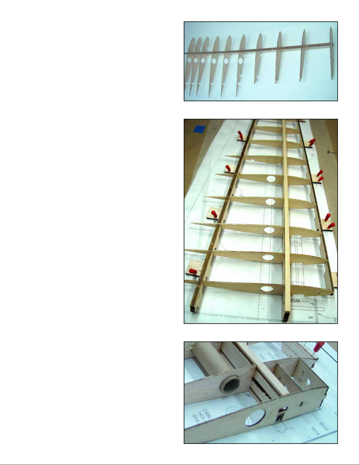
c 7Slide ribs W2 through W10 into their appro-
priate slots in the spar. Make insure that the
bottom of the top notch is ush with the top
of the spar.
Install and glue the Top Spar Doubler (SD
TOP) on the top of the spar at the root end.
Cut a piece of 3/32” x 1/4” x 36” spruce
stick to the exact length of the spar. Glue
this piece to the top of the spar. You should
now have ribs W2 through W9 captive in the
spar.
After step #9 you will have ribs W2 through W9 captive in
the spar assembly
Remove the dash cut section of material at
the root end of the spar assembly.
Place the leading edge tab of each rib into
the appropriate slot in FLE. DO NOR GLUE.
Slide the trailing edge (TE) under the aft
section of the ribs and insert each rib into
the appropriate slot in TE, Do not force any-
thing, when it is correctly lined up it will drop
onto place.
Align the alignment line in the TE stando
with the alignment line on the plans and se-
cure it to the building board with a pinning
tab tack glued to the stando. Like you did
with FLE. Continue down TE and secure ev-
ery other tab in the same manner. Insure that
each stando is at on the building board.
You can now apply glue to all the joints.
Start with the leading edge, then the trailing
edge. As you apply glue insure each rib is
bottomed tin the slot.
Install and glue the root rib (W1) and the tip
rib (W10).
Install and glue W14 between W1 and W2.
Install and glue W12 between W1 and W2.
Note that the slot in W2 is oversize. Install
W12 to the back of the slot. W13 will be in-
stalled in the front of that slot in a later step.
Cut a 11-7/8” length of cable tunnel tubing
and install in between W2 and W7. Glue it
at each rib.
Before applying glue to each joint, insure that each rib is
bottomed in the slot.
RIGHT: The photo illustrates all the work done in steps 15
through 18. Note the dash cut material in the spar has been
removed (Step 10). The hole in W1 is only used to install the
cable tunnel tube which terminates at W2 and W7.
3
c 24
c 23
c 22
c 21
c 20
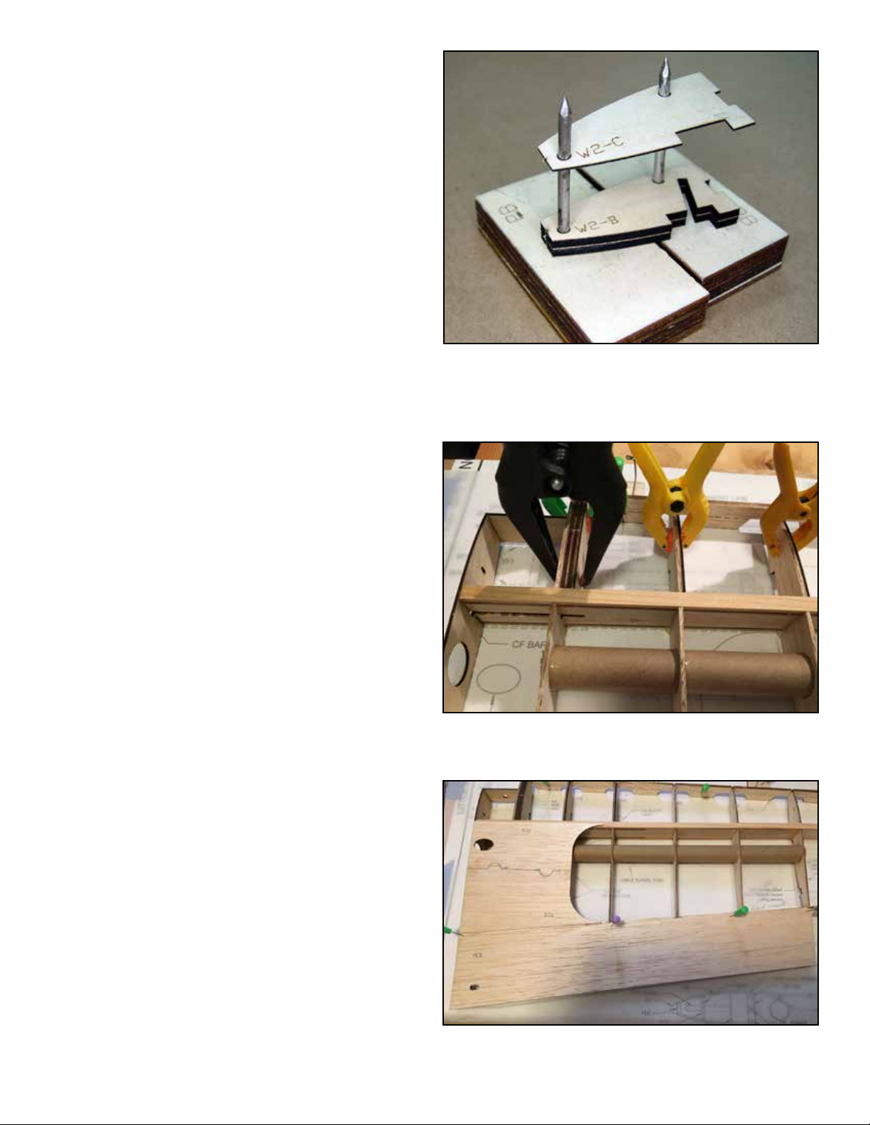
c 19 Use the registration pins to assemble the
landing gear slot, always assemble these
parts with the labeled side UP. Since these
parts are handed, it’s a good idea to assem-
ble both sets at the same time, then select
the correct one for the wing panel you are
working on. This will consist of two W2-B
parts and one W2-C. Place one of the W2-B
parts on the pins and glue another W2-B to
it. Install and glue a W2-C to this and then
install this assembly to the outboard side
of W2. Note that the W2-B/C assembly is
handed and a RIGHT handed version must
be assembled for the right wing.
The landing gear block consisting of two W2-B and one
W2-C being laminated together using the registration pins.
Note that when laminating handed parts, always laminate
them with the labeled side up. This will prevent you from
laminating two of the sane hand.
Install and glue W3-A to the outboard side
of W3.
Install and glue W4-A to the outboard side
of W4.
As cut, the trailing edge should be ush with
the top of the ribs between the root and W7.
However it will be slightly proud of the trail-
ing edge at the back edge. Sand the top of
the trailing edge until it is ush with the ribs
completely. Then install and glue the Trail-
ing Edge Sheeting (TES) to the trailing edge
and ribs between the root and W7. Note that
TES will be ush with the front side of the
trailing edge only between ribs W4 through
W7. It will be set back 1/16” between the
root and W4. Steps 19, 20 and 21, laminating the gear block assembly
as well as W3-A and W4-A, clamps are used to insure good
contact with the paring ribs.
Assemble one TCS TOP and one BCS to
form the center section sheeting. Glue this
assembly to ribs W1, W2 and W3 as well as
the trailing edge and the top of the spar.
Plane or sand the leading FLE to contour
with the leading edge of the ribs in prepara-
tion for sheeting the leading edge.
4
Top trailing edge (step 22) and top center section sheeting
(step 23) install and glued to the wing assembly.

5
c 28
c 27
c 26
c 25 Locate and prepare the top leading edge
sheeting (LES TOP). Best method to install
the top leading edge sheeting is to rst wet
the top side of the sheeting to insure no
splitting. I use a liberal application of Windex
with ammonia and leave it soak for at least
ve minutes. Use medium or thick CA along
the top of the spar only and install LES. Use
a straight edge or other weight to insure the
sheeting remains in contact with the spar
until the glue cures. After this glue cures, re-
move the wing assembly from the building
board and while holding the sheeting into
contact with the ribs and FLE apply fast CA.
Do a section at a time and let cure before
moving on to the next section.
Except for the area along the spar, the top leading edge
sheeting is glued from the open bottom with thin CA.
Snap o all the stand os from FLE and TE
but save them for use on the next wing pan-
el.
The landing gear block is laminated from
LG-A, LG-B and LG-C. Place LG-A on the
registration pins and glue LG-B to it. Note
that one end has an ellipse at the end of the
slot. Make sure these ends match and pull
LG-B snug against the opposite pin. Repeat
this procedure for LG-C.
Use Epoxy to install the gear block assem-
bly into the slots provided in W2, W3 and
W4. Note the end with the ellipse should be
at the root end.
The landing gear block is assembled by laminating LG-A,
LG-B and LG-C together. This will not only support the land-
ing gear but will also provide a small shelf to support the
sheeting.
When the gear block is installed, LG-C should stand 1/16”
proud of the ribs. This will bring it ush with the top of the
leading edge sheeting when installed.
ROOT

6
c 33
c 32
c 31 Assemble the center section sheeting from
one TCS and one BCS section and glue it
to ribs W1, W2 and W3 as well as the spar
and TE.
Installing the bottom leading edge sheet-
ing. The curve on the bottom leading edge
should not require wetting the balsa, install
it dry. Apply a bead of alphabetic resin (El-
mer’s or Titebond) to all ribs and the FLE.
Use a bead of medium CA on the top of the
spar and place the leading edge sheeting in
place and into contact with the spar. Hold it
in that position until the CA has cured. Place
the assembly on the bench with the sheeting
on the bottom and run a sharp blade along
the edge of FLE and trim the sheeting ush
with FLE. Then use strips of masking tape
around the leading edge to pull the sheeting
into contour and into contact with the ribs
and FLE. Set aside to cure.
c 30
c 29 Install and glue the Wing Servo Rails (WSR)
into the notches provided in W7 and W8.
Note that the screw holes should be to the
inside or towards each other. Use 1/4” piec-
es of 1/4” triangle stock to gusset these to
the ribs.
Install the servo rails and use some 1/4” length pieces of 1/4”
triangle stock as gussets between the ribs and the rails.
Sand the trailing edge to contour with the
ribs between W7 and W10 in preparation
for installing the trailing edge sheeting. In-
stall and glue the trailing edge sheeting to
ribs W1 through W7, the trailing edge and
the top trailing edge sheeting. Use clamps,
clothes pins or weights to maintain contact
with the ribs, trailing edge and top sheeting
until the glue cures.
When installing the bottom trailing edge, use plenty of clamps
along the trailing edge. A slight taper on both sheets will yield
a nice crisp trailing edge.
The cap strips are laser cut and should re-
quire little or no trimming to install. Note that
cap strips 7 and 8 on the bottom are notched
for the servo opening, after installing 7 and
8 on the bottom, run a bead of glue along
the interface of the rib and the cap strip on
the outside of the servo bay for support. In-
stall all cap strips, top and bottom, the num-
bers on the cap strips corresponds to the rib
they will attach to.
The cap strips on the bottom of ribs 7 and 8 are shaped to
accommodate the servo opening. The material indicated by
the arrows is scrap ll. You can use the servo mount for po-
sitioning of the ll.

7
c 2
c 1
c 38
c 37
c 36
c 35
c 34 Sand the leading edge smooth. Install and
glue the leading edge (LE). Use pins to sta-
bilize it and tape to pull it snugly against
FLE.
Plane and sand the leading edge shape to
contour. Use the leading edge template to
guide your work
Locate three Wing Tip (WT) parts and use
the registration pins to laminate the three
together to make the wing tip block. Glue
this assembly to W11 and when cured,
plane and sand to shape.
In the circles above are two gussets made from 1/4” triangle
stock, use on both sides. The arrow in th lower part is indica-
tion the glue llet between the cap strip and the rib.
Sand the trailing edge in the aileron bay at
and install and glue the Aileron Bay Trailing
Edge (ABTE). Sand ABTE to contour with
the trailing edge and wing tip. Use a knife
blade to open up the slot for the hinges and
test t the hinges for easy installation, they
should t slightly snug.
Use some scrap balsa to ll in at the front
and back the servo plate (SP) opening. Use
the Servo Plate as a guide.
This concludes the assembly of one wing panel. Place the remaining wing panel plans on the building
board and repeat all the above Wing Assembly Steps. Joining the wing halves will be done later after
we assemble the belly pan.
Assembling the Ailerons
Each aileron is laminated up from two (AIL)
parts using the registration pins to assem-
ble them. After laminating two AIL,s sand
the leading edge and both ends smooth.
NOTE: Although the ailerons will not be permanently attached until after the model is covered, cutting
the hinge slots and temporarily tting the assembly together will make the nal assembly mush easier.
Place the aileron next to the trailing edge
and mark the location of the hinges on the
aileron, then cut slots to accept the hinges.

8
c 3Temporarily secure the aileron assembly
to the wing with pins carefully centering it
in the trailing edge. Use a soft lead pen-
cil to mark the aileron assembly at the root
end and along the leading edge, top and
bottom. Use these lines to guide you when
you shape the ailerons. Plane and sand the
ailerons to shape.
c 5
c 4
Marking the aileron for shaping to the contour of the wing.
Mark the leading edge top and bottom as well as both ends.
The tip can be marked by laying a straight edge on the tip and
projecting a line over the end of the aileron.
Plane a chamfer on both sides of the lead-
ing edge of about 20 degrees but leave
about a 1/16” at at the center for hinging.
Use a sharp X-Acto knife to open up the
slots in the trailing edge for the aileron hing-
es. The slots should be open all the way
through FLE.
c 6Test t the ailerons to the wing with the CA
Hinges. The aileron control horns will be in-
stalled after covering.
c 2
c 1Locate all the belly pan components, BP-
1, BP-3, BP-5, BP-7, BP-9, BP-10 and BP-
11. Also the formed belly pan plastic parts.
Note that BP-11 terminates in an angle at
one end, this is the AFT end. Starting at the
front or opposite end install and glue BP-1
to BP-11. Install BP-3, BP-5, BP-7 and BP-9
from the front to the back. Install and glue
BP-10 at the angles end.
Belly pan formers attached to the belly pan keel. Use only
Pacer 560 canopy glue to attach this structure to the plastic
belly pan.
Locate the plastic formed belly pan. Note at
the sides where it changes from a curved
surface to a straight side. Use the side of
a pencil lead along this edge to dene it.
Trim o the excess plastic from the sides.
Leave a little excess for nal tting. Leave
both ends for now.
c 3Test t the balsa frame work into the plas-
tic pan. You will need to sand a bevel in
the edge of BP-10 so all the formers will t
snugly to the plastic belly pan. To glue any-
thing to a exible plastic part such as his you
need a glue that will remain ex able or it
will break away from the part. Two adhesive
that are excellent for this purpose are Pace
Formula 560 (Also called canopy glue) and
a glue called Grafter’s Pick which is a fabric
Rough trim the sides of the belly pan form using the line cre-
ated by rubbing the side of a soft lead pencil against ridge on
the sides.
ASSEMBLING THE BELLY PAN

9
c 4After curing, trim the front and back to
formers BP-1 in front and BP-10 at the
back. When trimming the plastic at F10, trim
it close and then sand it to exactly match
the angle and face of F10.
The belly pan assembly will be installed onto the wing assembly while attached to the fuselage as-
sembly this is as far as we can go for now. Put these assemblies aside and proceed with building the
fuselage.
After installing the former assembly, sand both ends ush
with the end formers.
glue available at craft stores. Apply a liberal
bead to all surfaces that will contact the belly
pan and install it. Set this aside to thoroughly
cure.
c 3
c 2
c 1
Both wing halves completed and ready for joining. Note the
carbon ber joiner and 1/8” dowel have been Epoxied into
the bottom wing half.
JOINING THE WING HALVES
Cut a 1/2” length of 1/8” dowel and round
over one end. Install it in the hole provided
in W1 just ahead of TE, let it protrude about
1/8”. Do this in one wing half only, this will
engage the hole in the opposite wing half
to align the wing halves when joining them.
Use Epoxy to install the 1/8” x 5/16” x 4”
carbon ber joiner in one wing half and let
this cure.
Apply Epoxy to one W1 on one of the wing
panels. Apply a liberal amount in the slot for
the carbon ber joiner. You can access this
though the hole in W1. Join the wing halves
and install and glue W13. Put the assembly
aside to cure.
c 4Cut two lengths of 3/16” dowel to 1-1/4”
long. Round over one end and smooth the
other end. Use Epoxy to install these in the
hole provided in W13. Make sure they are
glued to W12 as well, leave about 1/4” pro-
truding.
Completed wing assembly, the correct dihedral is set by W13.
Note the Cable opening plate. NOTE: In this photo the belly
pan has been installed. You will install that later in the build.

10
c 3
c 2
c 1Locate the four wheel pant halves. Note
that two of them have dimples in them for
the attachment system. Drill the four small-
er dimples out with a 1/16” bit. Drill out the
larger dimple with a 1/8” drill bit.
Trim the parts down to about 1/4” from the
edge of the part in preparation for trim-
ming out with the trim tool. You will need a
smooth at surface for the next operation.
While holding the part at on a smooth sur-
face make many very shallow cuts around
the periphery of the part. Do not attempt to
cut through but instead just try to score it.
It may take ten or fteen very light passes,
if you put too much pressure it can deect
the blade. Some parts of the plastic are
thinner than others and if you do happen
to break through, no problem just back o
on the pressure and continue. After you are
satised with the scoring, fold the edge of
the rim inward and it should break along
the score. Continue all the way around the
part. If there are any irregularities, a couple
swipes on a at piece of sand paper should
clean up the edge.
Landing Gear Assembly
The landing gear and wheel pants are assembled as a unit and then installed in the wing. To assemble
the wheel pants they must rst be trimmed to shape. This is easily accomplished using the plastic trim-
ming tool but rst we need to assemble the tool. Locate both parts of the trim tool. Note the tracing of
the X-Acto blade on one part. Use thin CA to glue the X-Acto blade to the part. Then glue the second
Trim Tool part to the rst encapsulating the blade.
RIGHT: The trimming tool components, a new blade must
be used when assembling the tool. The tool is used to only
score the plastic. The scrap can then be removed by exing
at the score. This will give you a clean straight edge to work
with.
Scoring the plastic with the trimming tool will give you a clean
straight edge to work with.
With a good score, the plastic will snap along the score line
leaving a straight edge.

11
c 9
c 8
c 7
c 6
c 5
c 4Remove any burrs from the inside of the
part from the drilling operation. It must be
smooth. Locate the screw plate for the half
you are working on and use a couple pins
through the screw holes to line it up. When
satised with the lineup, glue it with thin CA.
The holes in the screw plate must be aligned with the holes
in the wheel pant side. The screw plate must seat snugly to
the wheel pant.
Locate and prepare the Wheel Pant Joiner
(WPJ). Sand a taper in the last half inch on
both sides down to about 1/16” to allow for
the taper at the aft end of the wheel pant.
Use several pins to locate the center of
WPJ, this will allow the joiner to set only half
way into the wheel pant side.
Apply a liberal bead of Formula 560 Can-
opy Glue along the entire periphery on the
inside of the part and then install the joiner.
Use clothes pins or clamps to insure good
contact with the joiner. Remove any glue
that squeezes out so as not to inter fear
with the installation of the second half. Let
this cure throughly.
After taper sanding he trailing edge, pines are used to limit
the depth that WPJ can seat into the wheel pant half, it must
be half way.
Leave the pins in place on WPJ and apply
a liberal bead of Formula 560 Canopy glue
to the inner edge of the mating wheel pant
half and install it. Use rubber bands or tape
to pull the halves together.
When cured, remove the pins and apply
some Elmer’s wood ller to the center line
joint where necessary. When cured, sand
the joint smooth.
WPJ has been glued to the inboard wheel pant shells with
Pacer 560 Canopy glue.
Glue the outboard half of the wheel well shell to the inboard
assembly.
c 10 Open up the wheel opening and test t that
the wheel has plenty of clearance.

c 14
c 13
c 12
c 11 Locate the formed landing gear wire. I rec-
ommend about 2° of toe in on the main gear
to improve ground handling. When you
place the formed gear in the landing gear
slots in the wing and project a line along the
axles, it should cross the wing tip about 1”
back from the leading edge. Twist the gear
if necessary until you accomplish this.
Locate the landing gear leg components
WPB7, WPB8 and WPB9. Sand a bevel on
WPB7 from the line indicated at the bottom
of the part to the edge for clearance with
the wheel pant.
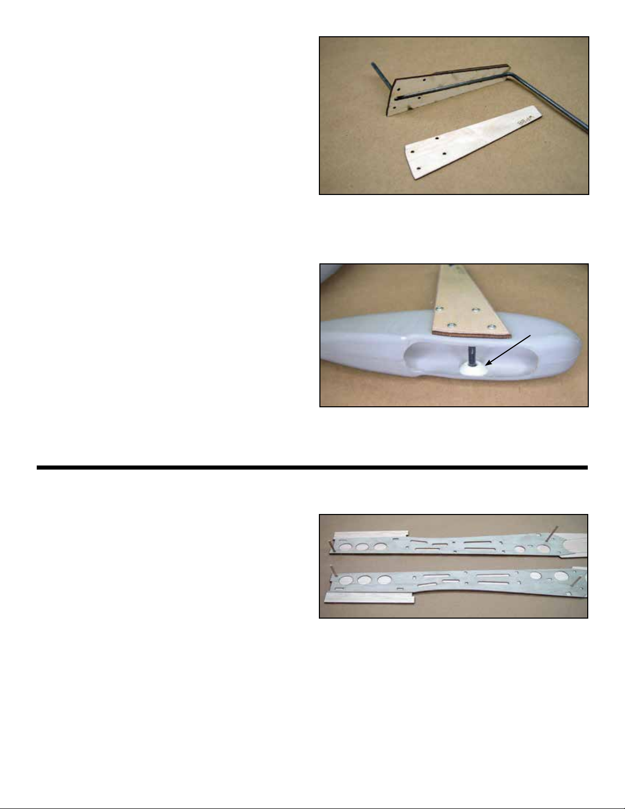
The landing gear strut cover components. Assemble these
parts with the labeled side up for a left and right hand set.
Note that all these parts are mirrored so
assemble all components with the labeled
side up and you will have a left and a right
assembly. Use the wire landing gear tem-
porarily placed in the slot of WPB9 to insure
the proper gap, then glue on WPB7.
c 15 Install the landing gear wire into the WPB7
WPB9 assembly and then glue on WPB8.
Sand a taper on the bottom of WPB8 from
the bottom up to the line indicator line.
Taper WPB7 from the bottom up to the line for clearance
with he top of the wheel pant.
Place part of the wire gear into the slot when installing WPB7
to WPB9 to insure that the gap remains large enough for the
wire leg.
12
13
c 18
c 17 Trim the axle so when installed to the wheel
pant, it almost touches the opposite (out-
board) side of the wheel pant.
Assemble the gear assembly to the wheel
pant with four #1 x 3/8” sheet metal screws.
When doing this side the axle support but-
ton onto the axle on the inside of the wheel
pant and glue it to the outboard side of the
wheel pant.
c 2
c 1
c 19
c 16
The gear leg assembly is attached to the wheel pant with
four #1 x 3/8” sheet metal screws. Trim the axle just shy of
touching the opposite side and then install the axle support
button.
Install and glue WPB-8 to WPB-9.
Glue WPB8 to WPB9
Remove the four screws and install the
wheel, then reinstall the four screws.
Final installation of the mains gear will be done
after covering the wing
FUSELAGE ASSEMBLY
Locate and prepare the two fuselage sides
(FS) and the two 1/64” ply fuselage dou-
blers (FD). Do not use a water based glue
such as carpenters glue to glue these two
components together. The moisture will
warp them and render them useless.
Use Epoxy or slow setting CA and glue the
doublers (FD) to the fuselage sides (FS).
Be sure to make a left and a right. Use a
piece of 1/8” dowel in the registration holes
to get perfect alignment.
Plywood doublers are glued to the fuselage sides using the
1/8” dowels for registration.
Glue formers C and D into their appropriate
location, refer to the plans for orientation.
c 3
c 6
c 5
c 4
14
Glue the other fuselage side assembly to
this assembly.
Use the square as shown here to insure that formers C and
D are at 90° to the fuselage side.
Locate the rewall (former A), former B
and the Battery Deck (BD). Glue BD to A
and then glue this assembly to B. Use the
square to insure they are at 90 degrees to
each other.
Former A (rewall) and former B assembled with he battery
deck (BD). Use the square to keep all these components
square to each other.
Glue the battery deck assembly to the fuse-
lage assembly.
Use Epoxy to install the battery deck assembly
c 7Install and glue the fuselage servo tray (ST)
to former D and the fuselage sides.
c 8Press two #8-32 blind nuts into the Wing
Bolt Plate (WPB) and glue it to former E
and the fuselage sides. The anges of the
nuts must be facing up.
The servo tray (step 7) and the wing bolt plate (step 8). In-
sure that both are engaged in there notches in the doubler.
15
c 20
c 19
c 18
c 17
c 16
c 15
c 13
c 12
c 11
c 10
c 9Cut two 11-5/8” pieces of 3/16” square bal-
sa stick and glue them to the top inside
edge from former D back to the stabilizer
area.
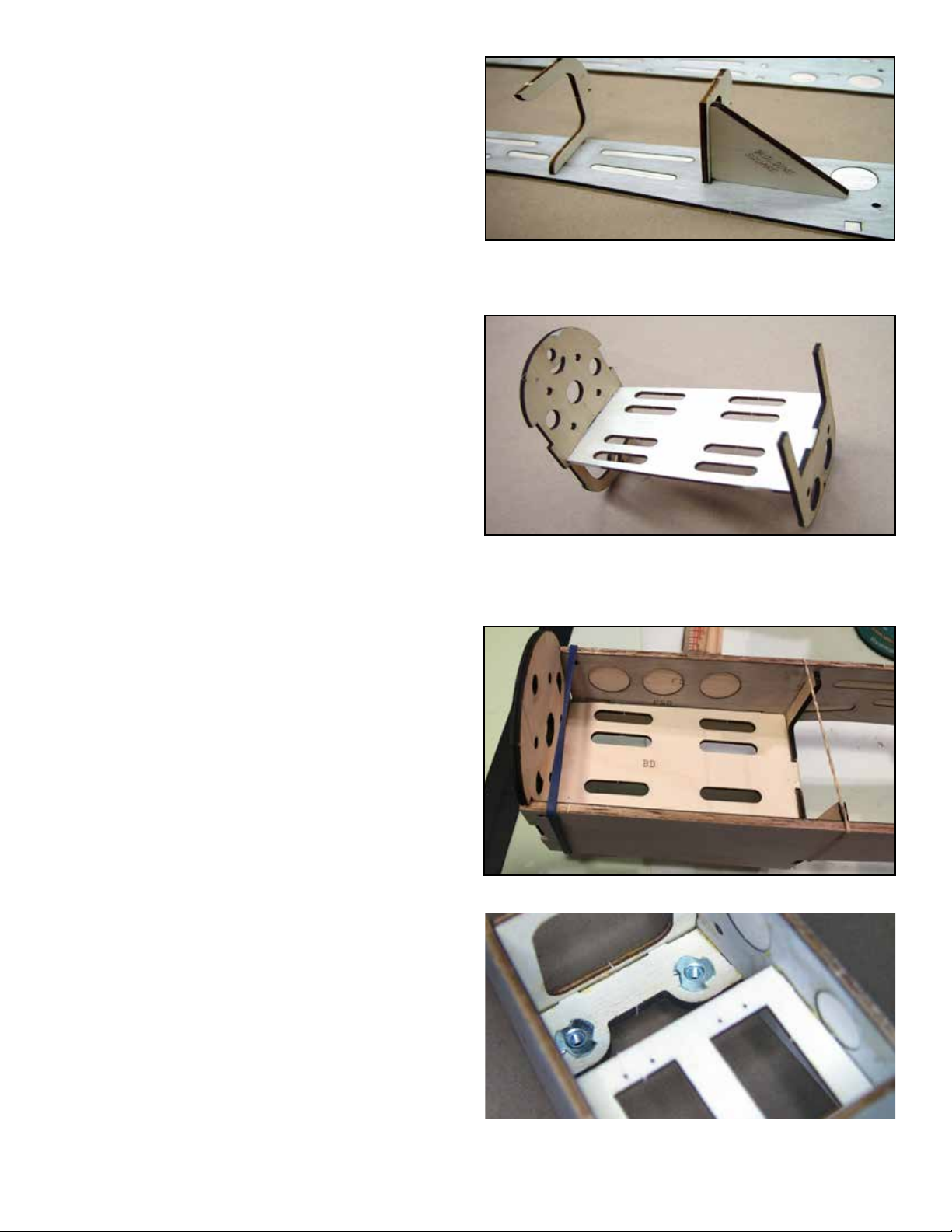
The photo above illustrates several steps
Locate formers F, G and H as well as the
Aft Fuselage Bottom (AFB). Install but do
not glue formers F, G and H into the fuse-
lage.
Step 9 Step 12
Step 10 &11
Install AFB, when all formers are bottomed
in their respective slots and AFB is ush
with the bottom of the fuselage, apply glue
to all formers and AFB.
Locate the Temporary Guide (Temp Guide)
and tack glue it to the back of former E.
This will support E1 At the correct angle
until the stringers are installed and then it
will be removed.
Install and glue E1 to the top of former E.
c 14 Cut two pieces of 3/16” square balsa to
11” long and install and glue them into the
notches provided in formers E1, F, G and H.
When the glue has set, remove the TEMP
GUIDE.
Step 13 Step 14
Locate the Turtle Deck Sheeting (TDS).
Install and glue it to the aft top fuselage.
The sheeting will sit on top of the fuselage
sides.
Illustrated above are installation of split former E1(step 13)
and the 3/16” stringers (step 14). Note that the TEMP GUIDE
has been removed.
Trim and sand the excess material of TDS
down just until you come in contact with
the top of the formers. It must be at, use a
sanding bar.
Install and glue the Turtle Deck Top (TDT).
Sand the TDT and TDS until they are ush
with E1 at the front.
Sand TDT and TDS until they are ush with
former H at the back.
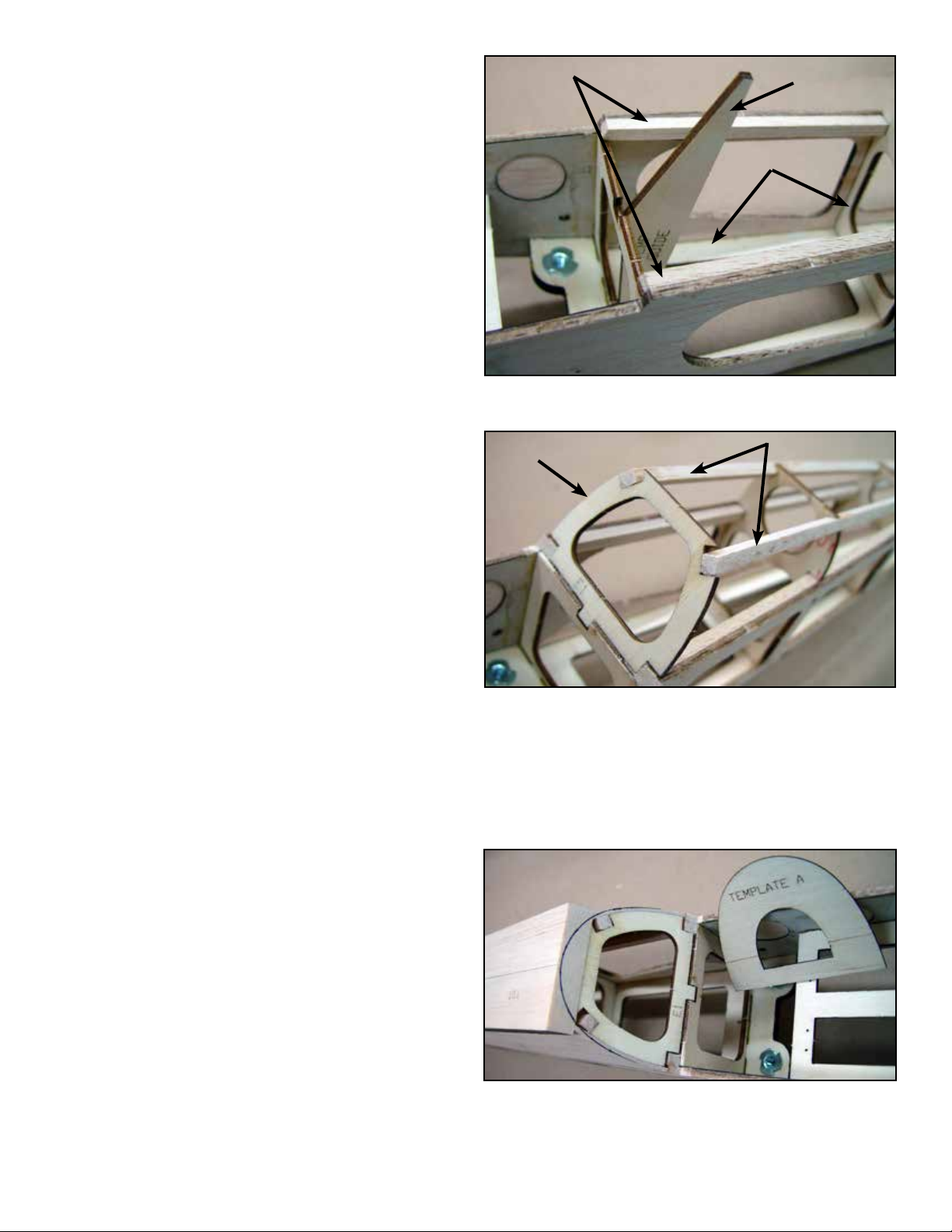
Next you will plane and sand TDT to shape
to form the turtle deck. Use Template A at
the front and Template B at the aft end to
mark the guide lines for shaping TDT.
Template A is used at E1 and template B is used at former H.
These are guide lines for shaping the turtle deck.
16
c 25
c 24
c 23
c 22
c 26
c 21
Locate the two For Deck Sheets (FDS) and
test t them to formers C and D. Wet the
outside of these sheets and then install
them between formers C and D. Glue them
rst to the fuselage sides and force them
over and into contact with the formers and
BCK and glue them. When cured, sand
them ush with formers C and D.
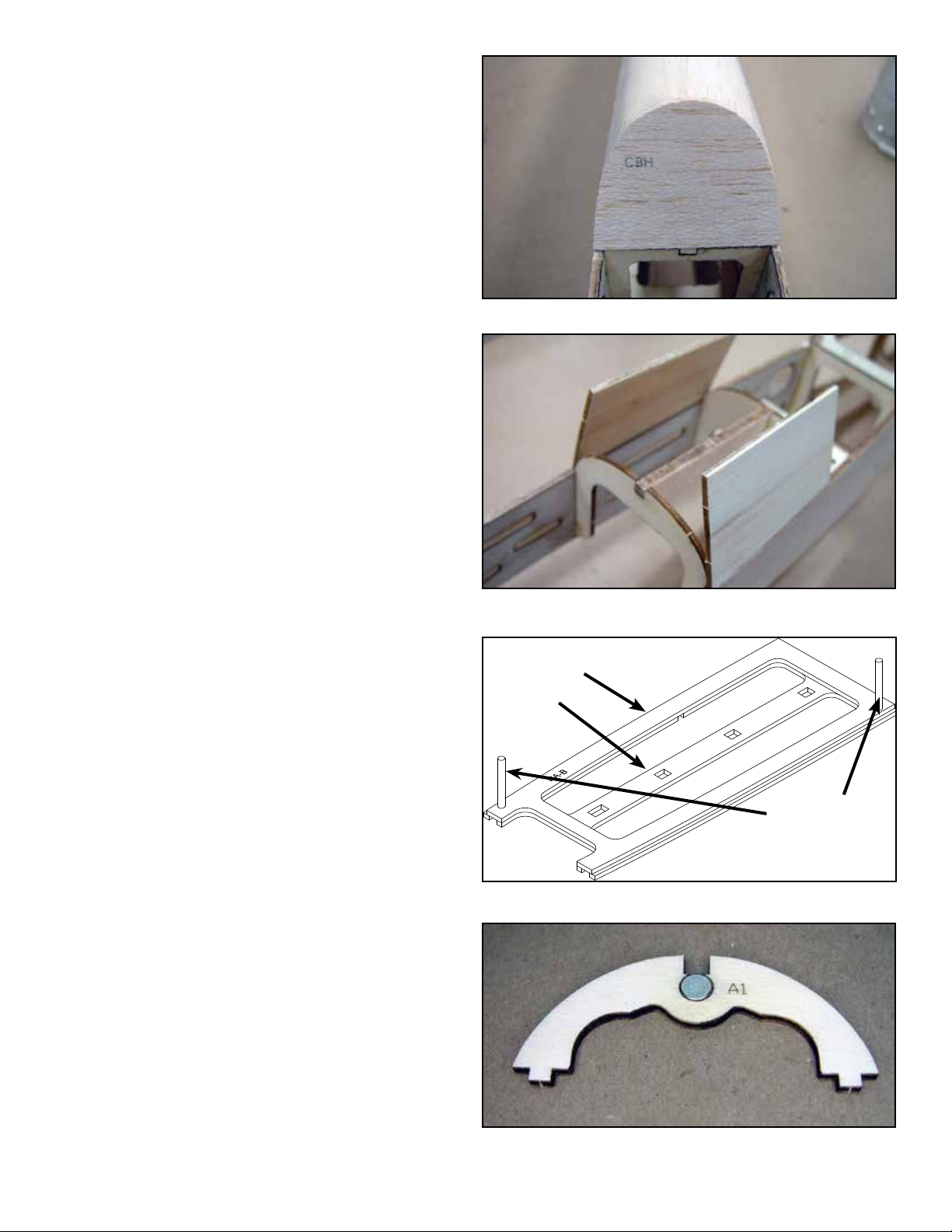
Install cockpit bulkhead CBH to E1
Install and glue the Cockpit Bulkhead
(CBH) to E1.
Locate and prepare the hatch components
HA-A, HA-B, HA-C, A1, B1 and C1. Lightly
sand the outer edges of HA-B to remove
any nubs and smooth the sides. When the
hatch is completed, HA-B will slide down
between the fuselage sides. Use the 1/8”
dowel pins and assemble HA-A and HA-B.
This is the forward hatch base.
HA-B
HA-A
1/8” DOWEL
The hatch base stack is laminated upside down using 1/8”
dowels for registration.
Install and glue HA-C to HA-A.
Install and glue formers A1, B1 and C1.
Use thick canopy glue or thick CA and in-
stall and glue a 1/8” x 1/4” magnet in the
hole provided in A1.
Glue FDS ush to the top of the fuselage and then shape and
glue it to the formers and BCK.
Glue a 1/8” x 1/4” magnet into A1. No need to worry about
polarity at this point.

17
c 27 Locate and prepare the Hatch sheeting
(HS). Note that the front corner is indicated
by the arrow. Wet the outside of HS. Place
the Hatch assembly at on the building
board, orient HS so the corner marked FC
is located at the front corner of the assem-
bly and the bench. With the edge of HS at
on the building board and snug up against
the hatch assembly, glue HS to HA-A.
c 34
c 32
c 31
c33
c 30
c 29
c 28 Pick the assembly up and pull the sheeting
tightly against B1 and HA-C and apply thin
CA. Do the same at A1 and HA-A.
With a sharp blade, carefully trim the sheet-
ing (HS) ush with the bottom of HA.
The whetted hatch sheeting is rst glued to HA-A and then
rolled over onto the formers and HA-HA-C and glued with
thin CA.
The hatch pull assembly ready to be installed into the hatch.
The pull wire will retract into the hatch when not in use.
Place the hatch onto the fuselage and sand
the sides to contour with the fuselage.
Place the plastic hatch pull on the front of
the hatch, centered and about 5/16” back
from the front. Mark the hatch sheeting for
the opening. Cut the opening and test t
the hatch pull.
Place a 1.8” x 1/4” magnet into the hole
provided in former A (rewall), let it snap
into place with the magnet in the hatch.
Mark the front of the magnet with a Sharpy.
Marker, Remove the hatch from the fuse-
lage and remove the magnet. Glue the
magnet into former A with the marked side
facing forward. Also install and glue a mag-
net in the hole provided at the bottom of
Former A.
Locate the plastic hatch pull. Cut a two inch
length of 1/32” wire and bend it into a U
shape so the legs will t through the two
holes in the hatch pull freely.
Place the U shaped wire into the holes in
the hatch pull, it should drop down into the
depression on top of the pull. About 1/8”
from each end of the wire, put a 90 degree
bend in the wire to prevent it from being
able to exit the plastic pull. Glue this as-
sembly into the hatch ush with the top of
the sheeting.
The hatch pull in the extended position. It will retract into he
recess when not in use. You can access it with a ngernail
or a magnet.
FC

18
c 38
c 37
c 36
c 35 Install and glue a length of 3/16” square
balsa in the notches provided at the bottom
of former A and B.
Locate and prepare the Forward Chin
Sheeting (FCS) and test t to the chin sec-
tion between former A and B. Wet the out-
side of the sheet and then glue it edge to
edge to the fuselage. When this has cured,
pull the sheeting into contact with Formers
A and B and the 3/16” square balsa and
glue it.
A piece of 3/16” square balsa provides the bottom keel be-
tween formers A and B.
Turn the fuselage over and install the wing.
Some sanding of the fuselage may be re-
quired until the wing seats correctly in the
wing saddle. W13 should butt rmly against
former B.
Sand the sheeting ush with former B and the fuselage sides.
Install the #8-32 Nylon bolts through the
bolt wells and then through the wing into
the blind nuts in the fuselage. Turn the
wing bolt wells so the low side is facing out-
ward away from the center of the fuselage.
When satised with the t, glue the wing
bolt wells to the wing.
The wing secured to the fuselage with the wing bolt and the
two bolt wells.
NOTE: Before proceeding with step 38,
check the alignment of the wing. With the
wing in position on he fuselage, measuring
from the wing tip trailing edge to the aft end
of the fuselage. Adjust the wing until both
sides are exactly the same. Mark the wing
and the fuselage so you can keep the wing
in this position while performing step #38.
Table of contents
Other TopNotch Products Toy manuals

TopNotch Products
TopNotch Products Li'l Pup User manual

TopNotch Products
TopNotch Products Mooney M-18 User manual

TopNotch Products
TopNotch Products SPUNKY User manual

TopNotch Products
TopNotch Products Seamaster II User manual

TopNotch Products
TopNotch Products Maverick User manual

TopNotch Products
TopNotch Products BUSH HAWK XP User manual
Popular Toy manuals by other brands


Fisher-Price
Fisher-Price DYM77 manual

KidKraft
KidKraft 65141 Assembly instructions

Fisher-Price
Fisher-Price H5698 instructions

Mattel
Mattel MERMAID FUN Kelly 52885 instructions

GREAT PLANES
GREAT PLANES Shoestring ARF instruction manual

Lightmybricks
Lightmybricks LEGO Gingerbread House 10267 Lighting Kit instructions


