Topotek TGIP10A User manual
TGIP10A 10x IP Gimbal
User Manual
V1.02
2020.06.08Revision

@2019topotek All Rights Reserved.
1
Contents
Warning and Disclaimer ................................................................................................................................ 2
1. Product Introduction ..................................................................................................................................... 3
2. Product List.................................................................................................................................................... 3
3. Mounting & Configuration............................................................................................................................ 3
3.1 Gimbal installation attention.............................................................................................................. 3
3.2 Gimbal structure description............................................................................................................. 5
4.Telecom ........................................................................................................................................................ 7
4.1Serial Port Communication..................................................................................................................... 7
4.2 UAV remoter control........................................................................................................................... 9
5. Specifications .............................................................................................................................................. 12

@2019topotek All Rights Reserved.
2
Warning and Disclaimer
Congratulations on purchasing your new TOPOTEK product.The information
in this document affects your safety and your legal rights and responsibilities.Read
this entire document carefully to ensure proper configuration before use.Failure to
read and follow instructions and warnings in this document may result in serious
to yourself or others,or damage to your TOPOTEK product or damage to other
objects in the vicinity.This document and all other collateral documents are subject
to change at the sole discretion of TOPOTEK. For up-to-date product
information,visithttp://www.topotek.com and click on the product page for this
product.
The TGIP10A has been calibrated before leaving the factory.No physical or
mechanical modificationor adjustment of the gimbal is required or
recommended.Do not add any other component or device to the camera.The TOP-
TGIP10A is a delicate instrument.Do not disassemble the gimbal or camera as this
will cause permanent damage.
In order to ensure the safety of flight control system after powering up, we
recommend you to remove all the propellers and use non -power-supply for the
gimbal. Keep the entire components far from children and flammable &
combustible materials!
Because we have no control of the use, mounting, assembly and modification processes,
TOPOTEK will not assume any legal responsibility for the injury or damage.

@2019topotek All Rights Reserved.
3
1. Product Introduction
TGIP10A, a great 3-axis gimbal for model aircraft enthusiasts, It provides a 10×optical
zoom.The 1/3 CMOS sensor supports approx.4 million effective pixels. With unique internal
wiring design, built-in IMU gimbal control module, specialized servo drive module, Network
IP output mode. And it can be widely applied to various model aircraft activities and
entertainments.
2. Product List
Gimbal ×1
With unique internal wiring design, built-
in IMU gimbal control module,
specialized servo drive module
Power &UART control
Network & SBUS Control Wire
Gimbal debug Micro-USB cable
(No standard parts, buy separately)
Micro-SD 存储卡
(No standard parts, buy separately)
3. Mounting & Configuration
3.1 Gimbal installation attention
1.pls don't hang on the frame when you not used gimbal,Long-term suspension will
accelerate damper deformation led to the decrease of the damper that jelly appearance;
2.Pls regular(7days)replace the gimbal damper(6pcs spare parts free)
3.Mount Gimbal installation the rod ,hanging hook and suspension plate must be
maintained between the absolute vertical and parallel to each other (as show bellowing),
wrong installation will cause the deformation of damper to lower then lead to suspension
effect。
4.When the gimbal connect HD transmission equipment,if the picture can't normal to
the display device,pls checking:
①. First, connect the Gimbal network interface directly to the PC or local hub. Open the
special ground station software, and see whether the picture is normal after the equipment is

@2019topotek All Rights Reserved.
4
powered on.check the picture is normal display and confirmed the gimbal normal working。
②.When connect the HD transmission equipment,pls Do not leave both on the same
level, to avoid interference with the equipment. At the same time check whether the
connection line is stable。
③.Gimbal camera output format support 1080P 30FPS,Please confirm whether the IP
address is the same network segment as the PC. In addition, whether the HD image
transmission equipment supports IP transparent transmission.

@2019topotek All Rights Reserved.
5
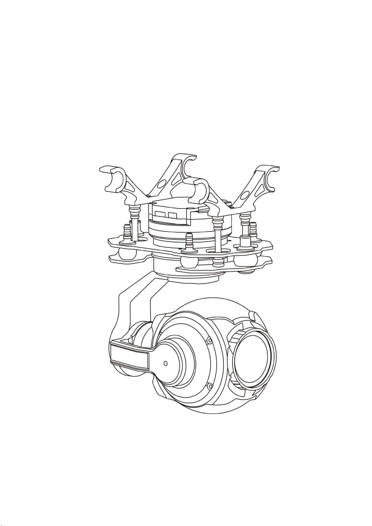
3.2 Gimbal structure description
Number
Corresponding
1
YAW Motor
2
Roll Motor
3
Tilt Motor
4
Camera
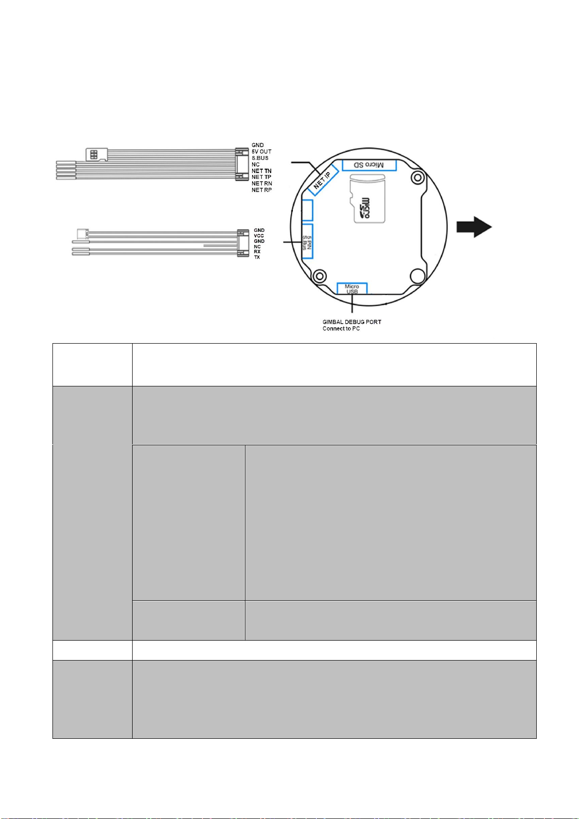
Product Interface:
1
2
3
4
@2019topotek All Rights Reserved.
6
1. Use serial port commands to control gimbal
2. Use PWM/SBUS to control gimbal
Power
Power supply:11V-26V (3S-6S Li battery)
Control
signal
1: S.Bus control mode
Take the s.bus lead in [network and SBUs control line], 5V power output and GND
line to form 3P s.bus signal output line
2: Network IP
control mode
GND:Signal Ground
5V OUT:5V voltage output
SBUS:SBUS control signal
NC:Not connect
NET TN:Network IP signal
NET TP:Network IP signal
NET RN:Network IP signal
NET RP:Network IP signal
3: Serial port control
mode
RX:Connect to external TX
TX:Connect to external RX
Video output
Network IP video output. RTSP HD stream.
Record TF
card
This camera can support the maximum 128GB 的Micro SD card。For high speed
write and read 1080P video stream, please use Class 10 or UHS-1 above Micro
SD card。
Note: Don’t remove the Micro SD card. It will damage the record video file
@2019topotek All Rights Reserved.
7
inside the card.
Gimbal
debug
Customer can debug the Gimbal through the Micro-USB port.
Electrical Interface Type/Definition/Function
Seq.
Pin Type
Interface Type
Definition
Function
1
6PIN
Power Interface
GND
GND
2
Power Interface
12V
3S-6S DC input
3
Control interface
GND
Gnd for signal
4
NC
NC
Not connect
5
Control interface
UART_IN
UART IN port
6
Control interface
UART_OUT
UART output
4.Telecom
4.1Serial Port Communication
Frame Structure
Frame
Head
(3char)
Target Bit
(2char)
Data Bit
(1char)
Control
Bit
(1char)
Flag Bit
(3char)
Data1
(char)
。。。
。
(char)
Data L
(char)
Calibration
(2char)
#TP
U/M/D/I/E/P
L
w/r
X1X2X3
D1
。。。
。
DL
CRC
Frame Head:
#TP:Fixed length,data length is 2;

@2019topotek All Rights Reserved.
8
#tp:Changing length, data length depends on length,maximum length is:0x0F;
Target Bit:
Source Bit: U: Uart;M: lens related command; D: system and image related
command; I: algorithm related command; E: thermal image related command; G:
gimbal related command;
Data Bit: byte and maximum length F
Control Bit: r – find; w – setup; c – utilize;
Data Bit: depends on data length;
Flag Bit: Flag to represent some status;
CRC: convert to HEX, use accumulation method, then convert result to ASC-II,
two bytes, high order is front;
Serial Port Control: baud rate 115200; data bit: 8; stop: 1; calibration: none.
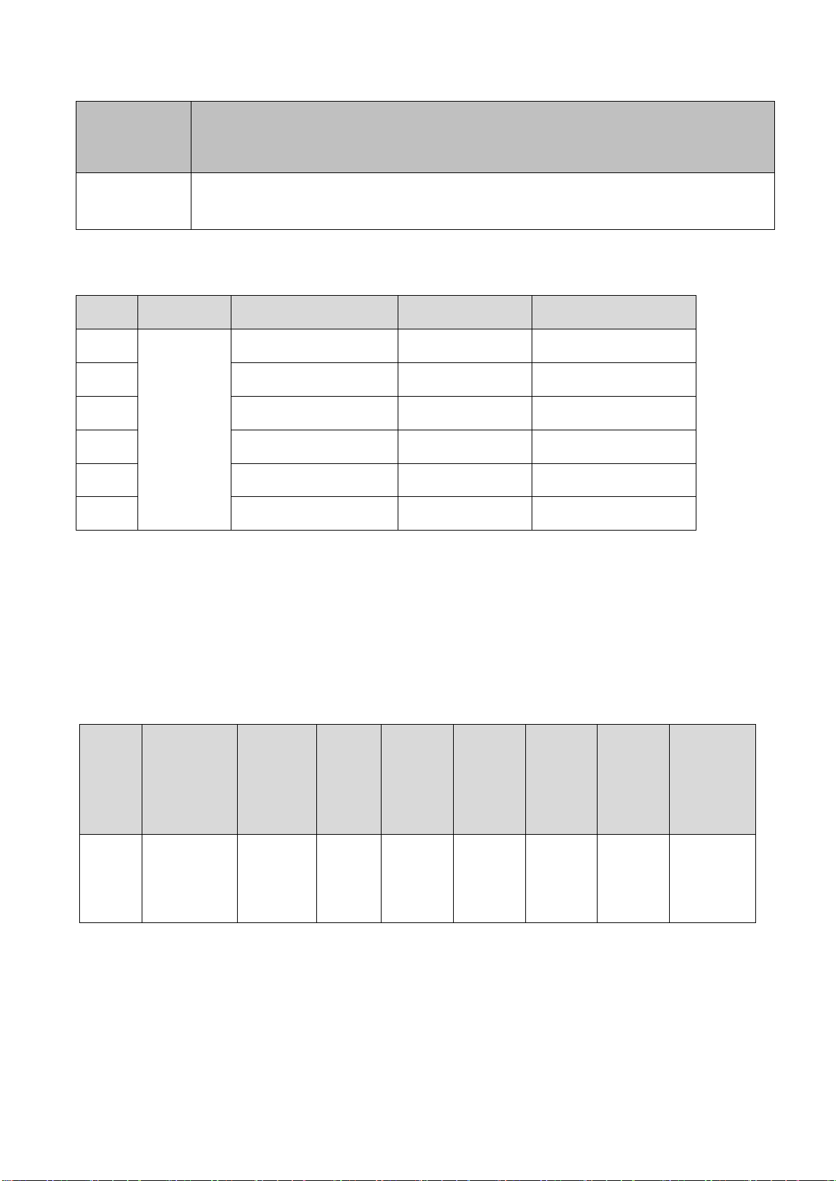
PC UART controler:
1. Gimbal Angle Control and Camera Control
@2019topotek All Rights Reserved.
9
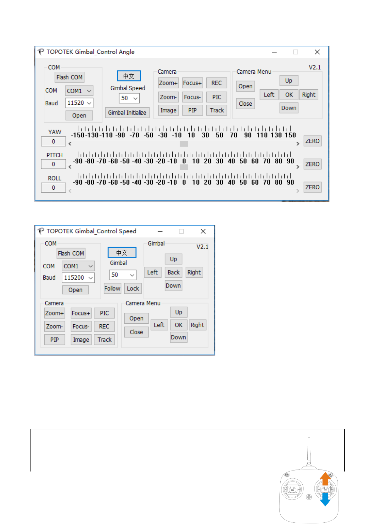
2. Gimbal Speed Control and Camera Control
4.2 UAV remoter control
The Gimbal can be controlled through the S.Bus port or Multi PWM channel. And each channel control a
function.
①Gimbal Pitch
Select a Rotary button switch or Rocker or 3 position switch:
Example the default THR channel 3:
Rocker upside: look up;

@2019topotek All Rights Reserved.
10
Rocker in middle position: no operation;
Rocker downside: look down
The setting with the rocker up and down corresponding
to the pitching direction of the platform can be adjusted.
②Gimbal Yaw
Select a Rotary button switch or Rocker or 3 position switch:
Example the default RUD channel 1:
Rocker left: Gimbal turn left;
Rocker in middle position: no operation;
Rocker right : Gimbal turn right
The setting with the rocker left and right corresponding
to the YAW direction of the platform can be adjusted.
③Camera Zoom
Select a Rotary button switch or Rocker or 3 position switch:
Example the default ELE channel 1:
Rocker upside: Zoom in; optical zoom 1x→10x
Rocker in middle position: no operation;
Rocker downside: Zoom out; optical zoom 10x→1x
The setting with the rocker up and down corresponding
to the camera’s zoom in or zoom out.
④Camera Focus
Select a Rotary button switch or Rocker or 3 position switch:
Example the default AIL channel 4:
Rocker left: Focus far;

@2019topotek All Rights Reserved.
11
Rocker in middle position: no operation;
Rocker right : Focus near
The setting with the rocker left and right corresponding
to the camera focus can be adjusted.
⑤Capture and Record
Select a Rotary button switch or 3 position switch
Example 3 position switch:
Position 1 capture,position 2 no action,
Position 3 record.
Position 2 to position 1:capture a picture
Position 2 to position 3:start record. Position 2 to position 3 again:stop record
operation.
The setting position 1 and position 3 can be adjusted。
⑥Gimbal lock and follow mode
Select a Rotary button switch or 3 position switch
Example 3 position switch:
Position 1 as direction follow,
position 2 no action,
Position 3 as direction locked.
Position 2 to position 1:direction follow mode, the gimbal’s Pitch and YAW axis
not move. And YAW axis will move follow the UAV direction.
Position 2 to position 3: direction locked mode, the gimbal’s Pitch and YAW axis
not move. And YAW axis will fix to a direction when UAV rotate.

@2019topotek All Rights Reserved.
12
5. Specifications
Product parameters
Name
TGIP10A
Input Power
3S-6S Li (11V-26V)
Working Current
250ma
Working Environment
-20℃~+50℃
Weight
365g
Max Controllable Rotation Speed
77 mm *105 mm *147mm
Controllable Rotation Range
TILT:-120 deg~ +15deg
Pan:-125 deg~ +125 deg
Attitude Control Accuracy
±0.02deg
Camera
Sensor
Effective Pixels:4 M
1/3" color CMOS 4 megapixel (2688 x 1520) image sensor
Lens
10× Optical Zoom
Aperture value:F2.0
F=4.9mm-49mm
Zoom movement speed:Optical wide angle - optical telephoto: 3.2
seconds
Focus movement time: (∞ near): 1.5 seconds
Diagonal FOV
66.6°-7.2°(A1)
Output video mode
Network IP mode RTSP stream
Output Format
1080P 30FPS
Min.Focus Distance
10 mm-300 mm
Video Formats
MOV
Working
Record
Exposure Compensation
Auto( default Shutter Priority )
Exposure Compensation
±2.0(1/3 increments)
Metering Mode
Average metering
Electronic Shutter Speed
Auto
White Balance
Auto/Daylight / cloudy / fluorescent light / tungsten lamp
Video Captions
Supported
One Key to 1×Image
Supported
Anti-flicker
50Hz,60Hz
PAL/NTSC
Supported
Supported SD Cards
Max.Capacity:128GB
Supported File Systems
FAT32
Assistant Software Supporting Platform
Windows XP/VISTA/7/8/10

@2019topotek All Rights Reserved.
13
If the product version needs to be upgraded or the functions are required to be
changed, please feel free to contact us for further technical support.
Name: Jianlong Cai
Mailbox: [email protected]
Contact: (+86) 13331001415
Hangzhou Topotek Vision Technology Co., Ltd.
R&D Center(Hangzhou): Room 1001, Building A, Hangzhou artificial intelligence Industrial

@2019topotek All Rights Reserved.
14
Park, 57 jianger Road, Binjiang District, Hangzhou, China.
R&D Center(Beijing): Room 909, Unit 1, Building N.O. 3, Zhujiang Moer International, Beiqing
Road 1, Changping District, Beijing, China.
Product Center(Shenzheng):Room 911, Shangmei Chuangke Building, Huanguan Nan Road,
Longhua District, Shenzheng, China.
Official Website:http://www.topotek.com
Version V1.02
Table of contents


