Topwell STICK-140i User manual
Inverter DC MMA Arc
Used for the STICK-140i/160i/180i/200i with input power of
220V/230V/240V,50/60Hz
-
+

CAUTION
Read the operating instructions!
The operating instructions provide an introduction to the safe use of the products.
• Read the operating instructions for all system components!
• Observe accident prevention regulations!
• Observe all local regulations!
• Confirm with a signature where appropriate.
General instructions
In the event of queries on installation, commissioning, operation or special conditions at the installation site,
or on usage, please contact your sales partner or our customer service department on +(86)571 88231791-808.
Liability relating to the operation of this equipment is restricted solely to the function of the equipment. No other
form of liability, regardless of type, shall be accepted. This exclusion of liability shall be deemed accepted by the
user on commissioning the equipment.
The manufacturer is unable to monitor whether or not these instructions or the conditions and methods are
observed during installation, operation, usage and maintenance of the equipment. An incorrectly performed
installation can result in material damage and injure persons as a result. For this reason, we do not accept any
responsibility or liability for losses, damages or costs arising from incorrect installation, improper operation or
incorrect usage and maintenance or any actions connected to this in any way.
2

Contents
Notes on the use of these operating instructions
1 Contents
1 Contents.....................................................................................................................................................
2 Safety instructions....................................................................................................................................
2.1 Notes on the use of these operating instructions .............................................................................
2.2 Explanation of icons..........................................................................................................................
2.3 General .............................................................................................................................................
2.4 Transport and installation .................................................................................................................
2.4.1 Ambient conditions ...............................................................................................................
2.4.1.1 In operation ...........................................................................................................
2.4.1.2 Transport and storage............................................................................................
3 Intended use ..............................................................................................................................................
3.1 Applications.......................................................................................................................................
3.1.1 MMA welding ..........................................................................................................................
3.2 Documents which also apply ............................................................................................................
3.2.1 Warranty ................................................................................................................................
3.2.2 Declaration of Conformity.......................................................................................................
3.2.3 Welding in environments with increased electrical hazards...................................................
3.2.4 Service documents (spare parts and circuit diagrams) .........................................................
3.2.5 Calibration/Validation .............................................................................................................
3.3 Summary .........................................................................................................................................
3.3.1 Brief Introduction ...................................................................................................................
3.3.2 Working Principle .................................................................................................................
3.3.3 Volt-Ampere Characteristic .....................................................................................................
4 Operation control and connectors ..........................................................................................................
4.1 Front view ........................................................................................................................................
4.2 Rear view ........................................................................................................................................
4.3 Machine control – Operating elements.............................................................................................
4.4 Welding current adjustment .............................................................................................................
4.5 Welding operation.............................................................................................................................
4.5.1 Striking arc way ....................................................................................................................
4.5.2 Manipulation of electrode .....................................................................................................
4.6 Welding parameters ...........................................................................................
4.6.1 Joint form in MMA ....................................................................................................................
4.6.2 Electrode selection .....................................................................................................
5 Design and function................................................................................................................................
5.1 General ...........................................................................................................................................
5.2 Machine cooling..............................................................................................................................
5.3 Workpiece lead, general ................................................................................................................
5.4 Transport and installation ...............................................................................................................
5.5 Mains connection.............................................................................................................................
5.5.1 Mains configuration ............................................................................................................
5.6 Duty cycle & Over heat......................................................................................................................
5.7 MMA welding....................................................................................................................................
5.7.1 Connecting the electrode holder and workpiece lead .........................................................
5.7.2 Select welding task .............................................................................................................
5.7.2.1 Arcforce correction (welding characteristics).........................................................
03
05
05
06
07
11
12
12
12
13
13
13
14
14
14
14
14
14
15
15
15
16
17
17
18
19
19
20
20
20
21
21
21
22
22
22
23
24
25
25
26
27
27
28
28
3

6 Maintenance, care and disposal ...........................................................................................................
6.1 General............................................................................................................................................
6.2 Maintenance work, intervals ...........................................................................................................
6.2.1 Daily maintenance tasks.....................................................................................................
6.2.1.1 Visual inspection ...................................................................................................
6.2.1.2 Functional test .......................................................................................................
6.2.2 Monthly maintenance tasks ................................................................................................
6.2.2.1 Visual inspection ...................................................................................................
6.2.2.2 Functional test ......................................................................................................
6.2.3 Annual test (inspection and testing during operation) .........................................................
6.3 Maintenance work ..........................................................................................................................
6.4 Disposing of equipment..................................................................................................................
6.4.1 Manufacturer's declaration to the end user ........................................................................
6.5 Meeting the requirements of RoHS................................................................................................
7 Rectifying faults.......................................................................................................................................
7.1 Checklist for rectifying faults ...........................................................................................................
8 Technical data..........................................................................................................................................
8.1 STICK-140i/160i ..............................................................................................................................
8.1 STICK-180I/200i ..............................................................................................................................
9 Accessories .............................................................................................................................................
9.1 Standard accessories ....................................................................................................................
Contents
Notes on the use of these operating instructions
29
29
29
29
29
29
29
29
29
29
30
30
30
30
31
31
33
33
33
34
34
4

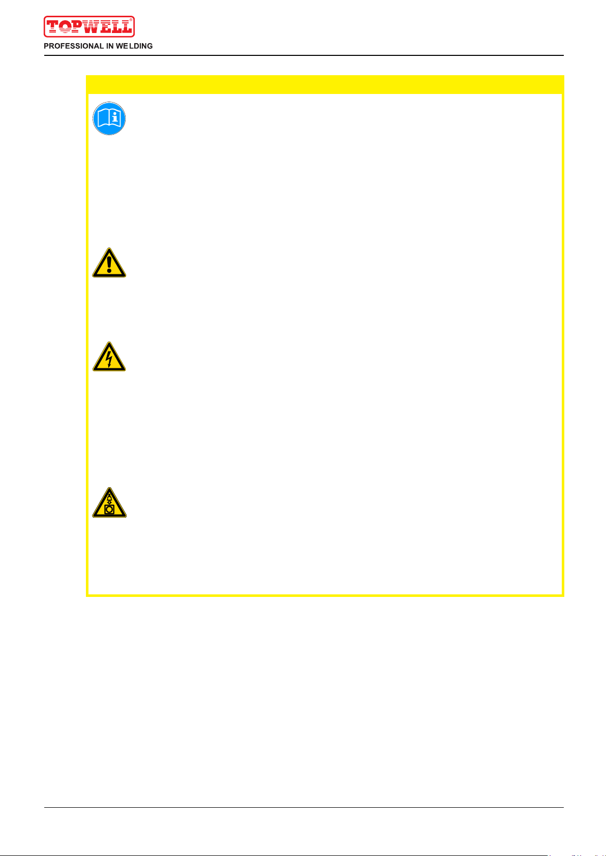
Safety instructions
Notes on the use of these operating instructions
2 Safety instructions
2.1 Notes on the use of these operating instructions
DANGER
Working or operating procedures which must be closely observed to prevent imminent
serious and even fatal injuries.
• Safety notes include the "DANGER" keyword in the heading with a general warning symbol.
• The hazard is also highlighted using a symbol on the edge of the page.
WARNING
Working or operating procedures which must be closely observed to prevent serious
and even fatal injuries.
• Safety notes include the "WARNING" keyword in the heading with a general warning
symbol.
• The hazard is also highlighted using a symbol in the page margin.
CAUTION
Working or operating procedures which must be closely observed to prevent possible
minor personal injury.
• The safety information includes the "CAUTION" keyword in its heading with a general
warning symbol.
• The risk is explained using a symbol on the edge of the page.
CAUTION
Working and operating procedures which must be followed precisely to avoid damaging
or destroying the product.
• The safety information includes the "CAUTION" keyword in its heading without a general
warning symbol.
• The hazard is explained using a symbol at the edge of the page.
NOTE
Special technical points which users must observe.
• Notes include the "NOTE" keyword in the heading without a general warning symbol.
Instructions and lists detailing step-by-step actions for given situations can be recognised via bullet
points, e.g.:
• Insert the welding current lead socket into the relevant socket and lock.
5

ENTER
ENTER
NAVIGATION
EXIT
4s
push
Safety instructions
Explanation of icons
Description
Press
Do not press
Turn
Switch
Switch off machine
Switch on machine
ENTER (enter the menu)
NAVIGATION (Navigating in the menu)
EXIT (Exit the menu)
4s Time display (example: wait 4s/press)
Interruption in the menu display (other setting options possible)
Tool not required/do not use
Tool required/use
2.2 Explanation of icons
Symbol
Press,turn
6
Safety instructions
General
2.3 General
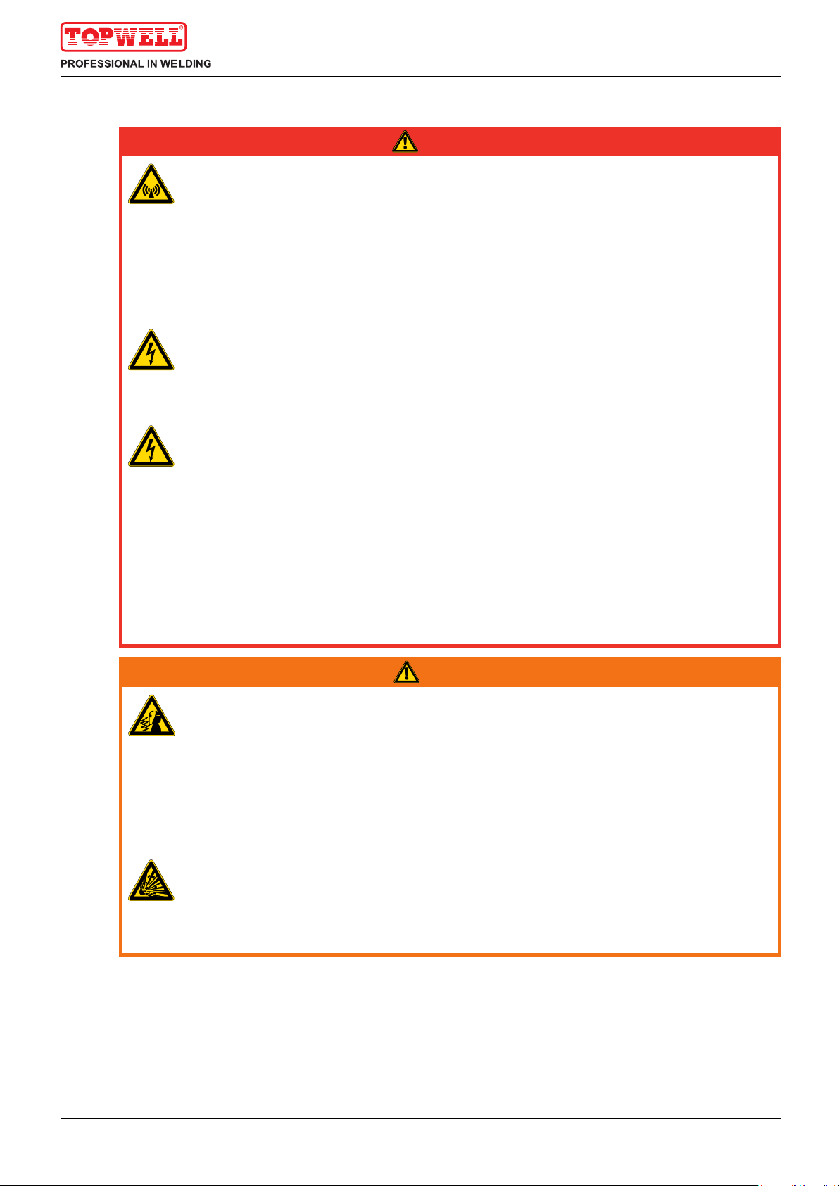
DANGER
Electric shock!
Welding machines use high voltages which can result in potentially fatal electric shocks
and burns on contact. Even low voltages can cause you to get a shock and lead to
accidents.
• Do not touch any live parts in or on the machine!
• Connection cables and leads must be free of faults!
• Switching off alone is not sufficient!
• Place welding torch and stick electrode holder on an insulated surface!
• The unit should only be opened by specialist staff after the mains plug has been
unplugged!
• Only wear dry protective clothing!
• Wait for 4 minutes until the capacitors have discharged!
Electromagnetic fields!
The power source may cause electrical or electromagnetic fields to be produced which
could affect the correct functioning of electronic equipment such as IT or CNC devices,
telecommunication lines, power cables, signal lines and pacemakers.
• Observe the maintenance instructions! (see Maintenance and Testing chapter)
• Unwind welding leads completely!
• Shield devices or equipment sensitive to radiation accordingly!
• The correct functioning of pacemakers may be affected (obtain advice from a doctor if
necessary).
Do not carry out any unauthorised repairs or modifications!
To avoid injury and equipment damage, the unit must only be repaired or modified by
specialist, skilled persons!
The warranty becomes null and void in the event of unauthorised interference.
• Appoint only skilled persons for repair work (trained service personnel)!
WARNING
Risk of injury due to radiation or heat!
Arc radiation results in injury to skin and eyes.
Contact with hot workpieces and sparks results in burns.
• Use welding shield or welding helmet with the appropriate safety level (depending on the
application)!
• Wear dry protective clothing (e.g. welding shield, gloves, etc.) according to the relevant
regulations in the country in question!
• Protect persons not involved in the work against arc beams and the risk of glare using
safety curtains!
Explosion risk!
Apparently harmless substances in closed containers may generate excessive pressure
when heated.
• Move containers with inflammable or explosive liquids away from the working area!
• Never heat explosive liquids, dusts or gases by welding or cutting!
7

Safety instructions
General
WARNING
CAUTION
Smoke and gases!
Smoke and gases can lead to breathing difficulties and poisoning. In addition, solvent
vapour (chlorinated hydrocarbon) may be converted into poisonous phosgene due to
the ultraviolet radiation of the arc!
• Ensure that there is sufficient fresh air!
• Keep solvent vapour away from the arc beam field!
• Wear suitable breathing apparatus if appropriate!
Fire hazard!
Flames may arise as a result of the high temperatures, stray sparks, glowing-hot parts
and hot slag produced during the welding process.
Stray welding currents can also result in flames forming!
• Check for fire hazards in the working area!
• Do not carry any easily flammable objects such as matches or lighters.
• Keep appropriate fire extinguishing equipment to hand in the working area!
• Thoroughly remove any residue of flammable substances from the workpiece before
starting welding.
• Only continue work on welded workpieces once they have cooled down.
Do not allow to come into contact with flammable material!
• Connect welding leads correctly!
Risk of accidents if these safety instructions are not observed!
Non-observance of these safety instructions is potentially fatal!
• Carefully read the safety information in this manual!
• Observe the accident prevention regulations in your country.
• Inform persons in the working area that they must observe the regulations!
Danger when coupling multiple power sources!
Coupling multiple power sources in parallel or in series has to be carried out by
qualified personnel and in accordance with the manufacturer's guidelines. Before
bringing the power sources into service for arc welding operations, a test has to verify
that they cannot exceed the maximum allowed open circuit voltage.
• Connection of the machine may be carried out by qualified personnel only!
• When decommissioning individual power sources, all mains and welding current leads have
to be safely disconnected from the welding system as a whole (danger due to inverse
voltages)!
Noise exposure!
Noise exceeding 70 dBA can cause permanent hearing damage!
• Wear suitable ear protection!
• Persons located within the working area must wear suitable ear protection!
8
Safety instructions
General
CAUTION
Obligations of the operator!
The respective national directives and laws must be observed for operation of the
machine!
• National implementation of the framework directive (89/391/EWG), as well as the
associated individual directives.
• In particular, directive (89/655/EWG), on the minimum regulations for safety and health
protection when staff members use equipment during work.
• The regulations regarding work safety and accident prevention for the respective country.
• Setting up and operating the machine according to IEC 60974-9.
• Check at regular intervals that users are working in a safety-conscious way.
• Regular checks of the machine according to IEC 60974-4.
Damage due to the use of non-genuine parts!
The manufacturer's warranty becomes void if non-genuine parts are used!
• Only use system components and options (power sources, welding torches, electrode
holders, remote controls, spare parts and replacement parts, etc.) from our range of
products!
• Only insert and lock accessory components into the relevant connection socket when the
machine is switched off.
Damage to the machine due to stray welding currents!
Stray welding currents can destroy protective earth conductors, damage equipment and
electronic devices and cause overheating of components leading to fire.
• Make sure all welding leads are securely connected and check regularly.
• Always ensure a proper and secure electrical connection to the workpiece!
• Set up, attach or suspend all conductive power source components like casing, transport
vehicle and crane frames so they are insulated!
• Do not place any other electronic devices such as drillers or angle grinders, etc., on the
power source, transport vehicle or crane frames unless they are insulated!
• Always put welding torches and electrode holders on an insulated surface when they are
not in use!
Mains connection
Requirements for connection to the public mains network
High-performance machines can influence the mains quality by taking current from the mains
network. For some types of machines, connection restrictions or requirements relating to the
maximum possible line impedance or the necessary minimum supply capacity at the interface
with the public network (Point of Common Coupling, PCC) can therefore apply. In this respect,
attention is also drawn to the machines' technical data. In this case, it is the responsibility of
the operator, where necessary in consultation with the mains network operator, to ensure that
the machine can be connected.
9

CAUTION
Safety instructions
General
EMC Machine Classification
In accordance with IEC 60974-10, welding machines are grouped in two electromagnetic
compatibility classes (see technical data):
Class A machines are not intended for use in residential areas where the power supply comes
from the low-voltage public mains network. When ensuring the electromagnetic compatibility of
class A machines, difficulties can arise in these areas due to interference not only in the supply
lines but also in the form of radiated interference.
Class B machines fulfil the EMC requirements in industrial as well as residential areas,
including residential areas connected to the low-voltage public mains network.
Setting up and operating
When operating arc welding systems, in some cases, electro-magnetic interference can occur
although all of the welding machines comply with the emission limits specified in the standard.
The user is responsible for any interference caused by welding.
In order to evaluate any possible problems with electromagnetic compatibility in the
surrounding area, the user must consider the following: (see also EN 60974-10 Appendix A)
• Mains, control, signal and telecommunication lines
• Radios and televisions
• Computers and other control systems
• Safety equipment
• The health of neighbouring persons, especially if they have a pacemaker or wear a hearing
aid
• Calibration and measuring equipment
• The immunity to interference of other equipment in the surrounding area
• The time of day at which the welding work must be carried out
Recommendations for reducing interference emission
• Mains connection, e.g. additional mains filter or shielding with a metal tube
• Maintenance of the arc welding equipment
• Welding leads should be as short as possible and run closely together along the ground
• Potential equalization
• Earthing of the workpiece. In cases where it is not possible to earth the workpiece directly,
it should be connected by means of suitable capacitors.
• Shielding from other equipment in the surrounding area or the entire welding system
10
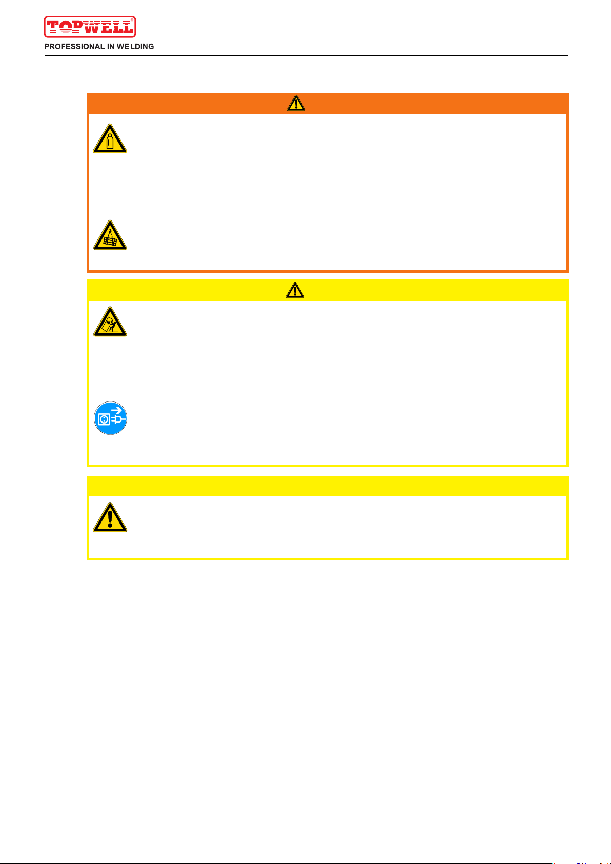
Safety instructions
Transport and installation
WARNING
CAUTION
CAUTION
Incorrect handling of shielding gas cylinders!
Incorrect handling of shielding gas cylinders can result in serious and even fatal injury.
• Observe the instructions from the gas manufacturer and in any relevant regulations
concerning the use of compressed air!
• Place shielding gas cylinders in the holders provided for them and secure with fixing
devices.
• Avoid heating the shielding gas cylinder!
Risk of accident due to improper transport of machines that may not be lifted!
Do not lift or suspend the machine! The machine can fall down and cause injuries! The
handles and brackets are suitable for transport by hand only!
• The machine may not be lifted by crane or suspended!
Risk of tipping!
There is a risk of the machine tipping over and injuring persons or being damaged itself
during movement and set up. Tilt resistance is guaranteed up to an angle of 10°
(according to IEC 60974-1, -3, -10).
• Set up and transport the machine on level, solid ground.
• Secure add-on parts using suitable equipment.
Damage due to supply lines not being disconnected!
During transport, supply lines which have not been disconnected (mains supply leads,
control leads, etc.) may cause hazards such as connected equipment tipping over and
injuring persons!
• Disconnect supply lines!
Equipment damage when not operated in an upright position!
The units are designed for operation in an upright position!
Operation in non-permissible positions can cause equipment damage.
• Only transport and operate in an upright position!
2.4 Transport and installation
11
Safety instructions
Transport and installation
2.4.1 Ambient conditions
CAUTION
CAUTION
Installation site!
The machine must not be operated in the open air and must only be set up and
operated on a suitable, stable and level base!
• The operator must ensure that the ground is non-slip and level, and provide sufficient
lighting for the place of work.
• Safe operation of the machine must be guaranteed at all times.
Equipment damage due to dirt accumulation!
Unusually high quantities of dust, acid, corrosive gases or substances may damage the
equipment.
• Avoid high volumes of smoke, vapour, oil vapour and grinding dust!
• Avoid ambient air containing salt (sea air)!
Non-permissible ambient conditions!
Insufficient ventilation results in a reduction in performance and equipment damage.
• Observe the ambient conditions!
• Keep the cooling air inlet and outlet clear!
• Observe the minimum distance of 0.5 m from obstacles!
2.4.1.1 In operation
Temperature range of the ambient air:
• -20 °C to +40 °C
Relative air humidity:
• Up to 50% at 40 °C
• Up to 90% at 20 °C
2.4.1.2 Transport and storage
Storage in an enclosed space, temperature range of the ambient air:
• -25 °C to +55 °C
Relative air humidity
• Up to 90% at 20 °C
12

Intended use
Applications
3 Intended use
This machine has been manufactured according to the latest developments in technology and current
regulations and standards. It must only be operated in line with the instructions on correct usage.
Hazards due to improper usage!
Hazards may arise for persons, animals and material objects if the equipment is not
used correctly. No liability is accepted for any damages arising from improper usage!
• The equipment must only be used in line with proper usage and by trained or expert staff!
• Do not modify or convert the equipment improperly!
WARNING
3.1 Applications
3.1.1 MMA welding
13
NOTE
Intended use
Documents which also apply
3.2 Documents which also apply
3.2.1 Warranty
For further information, please see the accompanying supplementary sheets "Machine
and Company Data, Maintenance and Testing, Warranty"!
DANGER
3.2.2 Declaration of Conformity
3.2.3 Welding in environments with increased electrical hazards
The designated machine conforms to EC Directives and standards in terms of its design
and construction:
• EC Low Voltage Directive (2006/95/EC),
• EC EMC Directive (2004/108/EC),
This declaration shall become null and void in the event of unauthorised modifications, improperly
conducted repairs, non-observance of the deadlines for the repetition test and / or non-permitted
conversion work not specifically authorised by the manufacturer.
The original copy of the declaration of conformity is enclosed with the unit.
3.2.4 Service documents (spare parts and circuit diagrams)
In compliance with IEC / DIN EN 60974, VDE 0544 the machines can be used in
environments with an increased electrical hazard.
Do not carry out any unauthorised repairs or modifications!
To avoid injury and equipment damage, the unit must only be repaired or modified by
specialist, skilled persons!
The warranty becomes null and void in the event of unauthorised interference.
• Appoint only skilled persons for repair work (trained service personnel)!
Original copies of the circuit diagrams are enclosed with the unit.
Spare parts can be obtained from the relevant authorised dealer.
3.2.5 Calibration/Validation
We hereby confirm that this machine has been tested using calibrated measuring equipment, as
stipulated in IEC/EN 60974, ISO/EN 17662, EN 50504, and complies with the admissible tolerances.
Recommended calibration interval: 12 months
14
Intended use
Summary
3.3 Summary
3.3.1 Brief Introduction
15
ŸSTICK-serires welders are general MMA arc welder which adopts the latest pulse width modulation
(PWM) technology and the insulated gate bipolar transistor (IGBT) power module. It can change work
frequency to medium frequency so as to replace the traditional hulking work frequency transformer with
the cabinet medium frequency transformer. Thus, it is characterized with portable, small size, low
consumption and etc.
ŸSTICK-serires have excellent performances: constant current output makes welding arc more stable;
fast dynamic response speed reduces the impact from the arc length fluctuation to the current;
accurate stepless current adjustment and pre-setting function. There are also some automatic
protection functions for under voltage, over current, over heat, etc. inside the welders, when the
problems listed before occurred, the alarm on the front panel is light and at the same time the output
current will be cut off. It can self-protect and prolong the using life and greatly improved the reliability
and practicability of the welders.
ŸWhile MMA operation, if the electrode touches workpiece over two seconds, the welding current will
drop to the minimum current automatically to protect the electrode.
Ÿ MMA——Manual Metal Arc welding;
ŸPWM——Pulse-Width Modulation;
ŸIGBT——Insulation Gate Bipolar Transistor;
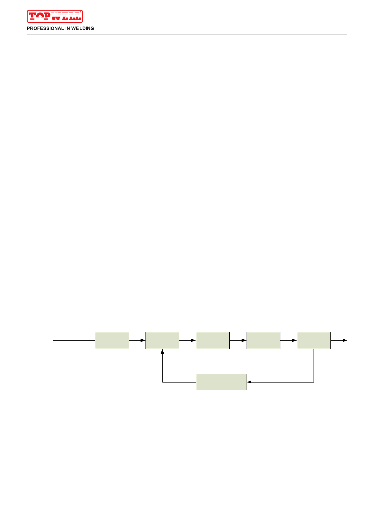
3.3.2 Working Principle
The working principle of MINI ARC-serires welder is shown as the following figure. Single phase
220V/230V±10% work frequency (50/60 Hz) AC is rectified into DC (about 300V), then is converted to
medium frequency AC (about 20KHz) by inverter device (IGBT module), after reducing voltage by medium
transformer (the main transformer) and rectified by medium frequency rectifier (fast recovery diodes), and
is outputted by inductance filtering. The circuit adopts current feedback control technology to insure
current output stably. Meanwhile, the welding current parameter can be adjusted continuously and
steplessly to meet with the requirements of welding craft.
Single phase,AC
220/230V 50/60Hz Rectify DC Inverter AC Medium
frequency
transformer
Medium
frequency
rectify
Hall device
Current positive
feedback control
DC DCAC
Intended use
Summary
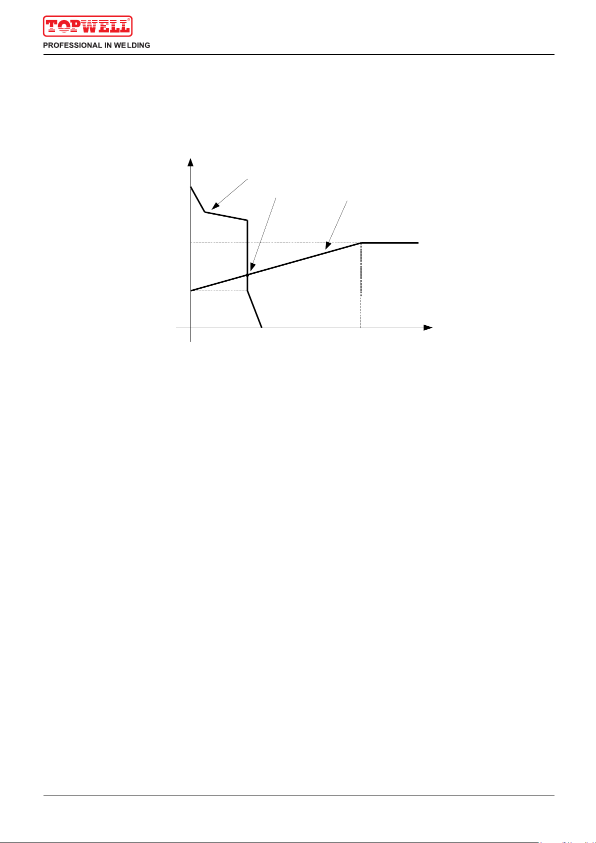
3.3.3 Volt-Ampere Characteristic
16
ŸSTICK-serires welders have excellent volt-ampere characteristic, seeing the following graph. In MMA
welding, the relation between the rated loading voltage U2 and welding current I2 is as follows:
ŸWhen I ≤600A, U =20+0.04 I (V); When I >600A,U=44(V).
2 2 2 2 2
64
44
20
0 600 I2(A)
U2(V)
Voltampere characteristic
Working
point The relation of the rated loading
voltage & welding current
Operation control and connectors
Front view
4 Operation control and connectors
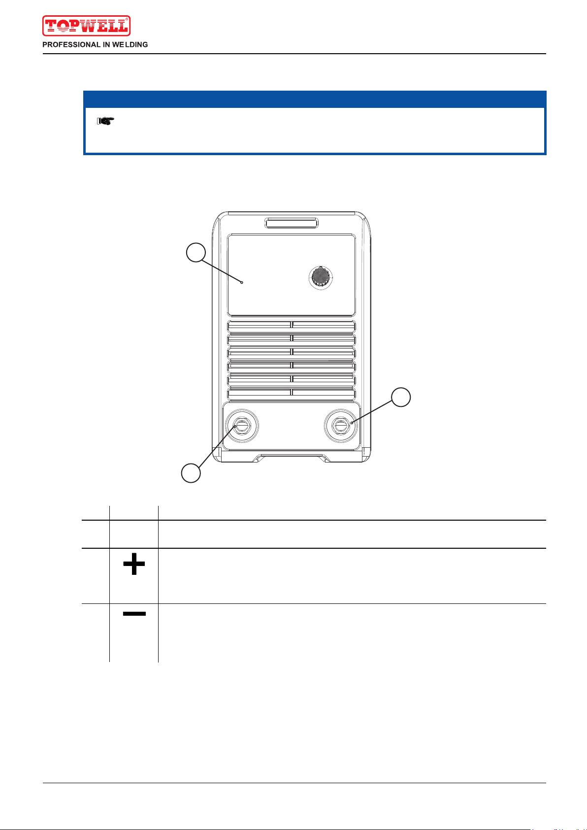
4.1 Front view
17
NOTE
The maximum possible machine configuration is given in the text description.
If necessary, the optional connection may need to be retrofitted (see "Accessories"
chapter).
1
2
3
Item Symbol Description 0
1
2
3
Machine control
See Machine control – operating elements chapter
Connection socket, “+” welding current
Welding connection Positive polarity output
Connection socket, “-” welding current
Earth connection Negative polarity output

2
Item Symbol Description 0
1 Main switch, machine on/off
2 Mains connection cable
Operation control and connectors
Rear view
4.2 Rear view
18
1
Power pilot lamp, This pilot lamp when lit indicates that the machine is on

Operation control and connectors
Machine control – Operating elements
4.3 Machine control – Operating elements
19
-
+
12
3
Item Symbol Description 0
1 Standby indicator light
2 Overheating indicator light
3 Welding current regulation Set welding current(5-160A).
STICK-160i
4.4 Welding current adjustment
ŸTake example for STICK-160i
ŸWelding current range is 5~160A.
ŸMINI ARC-serires welder has the function of welding current pre-setting. Before
welding, adjusting welding current, the welding current display will show the ampere.
It is convenient to set parameters and adjust accurately.
-
+

Operation control and connectors
Welding operation
4.5 Welding operation
4.5.1 Striking arc way
20
ŸKnocking arc: take the electrode upright to touch the workpiece, after forming short circuit, quickly lift
up about 2~4 mm, and arc will be ignited. This method is difficult to master. But in the welding for the
brittle or hard steel, it is better to use knocking way.
electrode
workpiece
electrode electrode
workpiece workpiece
Take the electrode upright The Electrode touch the workpiece
upright
up
touch
2~4mm
Lift up for about 2-4mm
ŸLifting arc: take the electrode to scrape the workpiece for striking arc. But it may cause the arc scratch,
so must to lift arc in the groove.
4.5.2 Manipulation of electrode
electrode
workpiece
weld
1
2
3
2
1-electrode moving; 2-the electrode swing right & left; 3-the electrode move along weld
ŸIn MMA welding, there are three motions to being
matched in the end of electrode: the electrode
moving to the molten pool along axes; the
electrode swing right and left; the electrode
moving along welding way.
ŸThe operator can choose the manipulation of
electrode based on welding joint sharp, welding
This manual suits for next models
3
Table of contents
Popular Welding System manuals by other brands

EWM
EWM Tetrix 351 AW FW operating instructions

ESAB
ESAB MT-450W instruction manual

Miller Electric
Miller Electric Universal Large Cylinder Cart owner's manual

ESAB
ESAB Cadd Tig 1500i TA34 Service manual

Magmaweld
Magmaweld ID 250T DC PULSE user manual

Lincoln Electric
Lincoln Electric INVERTEC SVM158-A Service manual


