Toray HSU-1515 User manual

Issued in June 2009
Revised in March 2014
TORAY Submerged UF
MEMBRANE ELEMENT
Instruction Manual
Model:
HSU-1515
issued by Toray Industries, Inc.
Water Treatment & Environment Division
2-1-1, Nihonbashi-Muromachi, Chuo-ku, Tokyo 103-8666 Japan
Tel: +81-3-3245-4557
Fax: +81-3-3245-4913
URL: http://www.toray.com
BJADJCAG

Content
I. Introduction......................................................................................................1
1. Characteristics of Toray Submerged UF Membrane Rack ...............................1
2. Applications of Toray Submerged UF Membrane Rack....................................2
II. For Your Safety................................................................................................3
1.Safety Instruction for Unpacking and Installation .............................................4
2. Safety Instruction for Filtration Operation........................................................6
3. Safety Instruction for Chemical Cleaning.........................................................8
4. Safety Instruction for Disposal.........................................................................9
III. Outline...........................................................................................................10
1. Outline of membrane.....................................................................................10
2. Outline of element......................................................................................... 11
3. Outline of rack...............................................................................................12
IV. Specifications and Configuration....................................................................13
1. Specifications of Membrane ..........................................................................13
2. Specifications and Configuration of Element .................................................14
3. Specifications and Configuration of Rack ......................................................16
4. Feed water and Cleaning Limits....................................................................20
V. Installation.....................................................................................................21
VI. Operation.......................................................................................................25
1. Advance preparation .....................................................................................25
2. Filtration........................................................................................................27
3. Backwash and Air-scrubbing.........................................................................29
4. Toray Maintenance Cleaning.........................................................................31
5. Air Diffuser Cleaning......................................................................................32
6. Temperature Correction Factor......................................................................34
VII. Integrity Test and Maintenance......................................................................35
1. Pressure Decay Test (PDT)...........................................................................35
VIII.Maintenance..................................................................................................38
IX. Storage of New Element and Rack after use..................................................42
1. Storage of New Membrane Element..............................................................42
2. Storage of Rack after use..............................................................................42

1
I. Introduction
Toray Submerged UF Hollow Fiber Membrane Rack is the submerged type hollow
fiber UF (ultra filtration) membrane rack developed with the polymer science and
the membrane fabrication technologies accumulated for a long time in Toray
Industries, Inc.
The membrane material is Polyvinylidene fluoride (PVDF). The nominal molecular
weight cut off of the membrane is 150,000 daltons. It has been confirmed that more
than 90% of 150,000 daltons model polymers is consistently removed.
The element, with Polyethylene (PE) protective cylinder, is submerged type. The
maximum operating trans-membrane pressure is 100 kPa (14.5 PSI). The flow
direction is outside to inside which is suitable for high turbidity water treatment
because the air-scrubbing can be adopted to remove suspended solid effectively.
1. Characteristics of Toray Submerged UF Membrane Rack
(1) High Filtration Flux
It provides high filtration flux and stable operation for the filtration of various
raw water sources. The membrane is made with a special spinning method,
which enables high permeability and high fouling resistance.
(2) Excellent Water Quality
It provides very good water quality for the filtrate, extremely low turbidity since
the membrane has 150,000 dalton nominal molecular weight cut off. The rack is
recommended to be applied in high turbidity water treatment, such as for
tertiary treatment of sewage water and industrial waste water reuse.
(3) High Mechanical Strength
The membrane has very high mechanical strength because it is made of PVDF
with the special spinning method developed by Toray. The rack provides high
integrity and durability under recommended operating conditions.

2
(4) High Chemical Durability
The membrane material is PVDF, which allows you to clean the membrane with
high concentrations of chlorine and with high concentrations of acid resulting in
better cleaning and longer sustainable membrane flux rates.
2. Applications of Toray Submerged UF Membrane Rack
- Drinking Water Production
Membrane Elements certified with NSF61
- Tertiary Treatment of Sewage Water
- Industrial Water Production
- Reuse of Industrial Waste Water
3
II. For Your Safety
- Please be sure to read and follow the instructions below before using. This
manual should be retained for future reference.
- Follow the safety precautions as they are intended to protect operators and
equipment from various risks such as physical harm and/or property
damage. The following table shows a level of potential risk for each
indicated symbol.
This symbol indicates an imminent hazardous situation
which will result in serious injury or death when the
instruction is not observed.
This symbol indicates a potentially hazardous situation
which will result in serious injury or death when the
instruction is not observed.
This symbol indicates a potentially hazardous situation
which might result in injury or property damage when
the instruction is not observed.
- The following table explains the information to be noted.
“Prohibited”
This symbol indicates a prohibited action or procedure.
“Instruction”
This symbol indicates an important action or procedure
which has to be taken without fail.
! DANGER
! DANGER
! WARNING
! WARNING
! CAUTION
! CAUTION
Prohibited
!
!
Instruction

4
1. Safety Instruction for Unpacking and Installation
Be sure to wear safety gear such as rubber gloves and safety glasses
for unpacking. The membrane is packaged in sodium hypochlorite
solution (100mg/L). If the solution happens to touch on the skin, wash
the affected part with running water. If the solution happens to get in the
eyes or mouth, wash the affected part with sufficient amounts of clean
running water for more than 15 minutes and see the doctor immediately.
When lifting rack, please attach chains or slings to it and raise it straight
upward calmly to prevent it from shaking. Please never allow any
person under lifted article.
When installing rack, please set up a foothold in advance. Please never
do the work above the rack. Use protective equipment to ensure the
safety of workers.
Be sure to wear safety gear such as a helmet and safety shoes to avoid
injury.
The preservative solution should be washed out before using the
element. After that, keep clean water on the element to prevent the
membranes from drying out (for example, sprinkle on the element with
water). Do not allow the element to dry even for a few hours.
The element should not be frozen.
! DANGER
! DANGER
!
!
Instruction
! WARNING
! WARNING
!
!
Instruction
! CAUTION
! CAUTION
Prohibited
Prohibited
!
!
Instruction
!
!
Instruction
5
Be careful not to damage or dent the element during handling.
IDF/ISO Clamp Union Fittings 1.5 are applied for connecting the
element of HSU-1515 to the piping. Do not overtighten the cramp as
damage to the element may occur.
Keep the connection surface free of any dirt or oils.
Be sure not to install the element upside down. Confirm the element
installed in the right direction.
Be sure to install the element vertically for effective air scrubbing.
Be sure to store the element transversely.
At transportation, storage and installation rack, please take appropriate
measures to protect rack from damage.
Do not put any heavy objects on the rack. Please take care to protect
the rack from collision with other objects.
Please take adequate measures to protect rack from sparks caused by
welding, fusion cutting or grinding throughout the entire process from
installation work to operation setup.
!
!
Instruction
!
!
Instruction
Prohibited
Prohibited
Prohibited
!
!
Instruction
!
!
Instruction
!
!
Instruction

6
2. Safety Instruction for Filtration Operation
Flush all the piping out with clean water and make sure no debris is
remaining in the piping prior to charging water to the element from the
piping.
Confirm that the preservative chemical in the element and the piping is
completely washed out before starting the filtration operation. The
preservative chemical is harmful to humans.
Prior to use, make certain elements are washed. Filtrate water should
be drained unless it meets the required quality.
Protect elements from direct sunlight and ultraviolet light. Ultraviolet
light can degrade element housing and membranes.
Constantly monitor filtrate water quality such as turbidity and/or the
number of particles during filtration, and stop the operation if abnormal
water quality is detected.
Do not exceed the maximum applicable trans-membrane pressure for
filtrating 100 kPa or for backwashing 200 kPa. Higher pressures can
damage the elements. Do not exceed the maximum temperature of 40
degree C . The higher temperature damages the elements.
Do not freeze the elements.
! DANGER
! DANGER
!
!
Instruction
! WARNING
! WARNING
!
!
Instruction
Prohibited
Prohibited
!
!
Instruction
!
!
Instruction
!
!
Instruction

7
The operating conditions, including the filtration flux and the periodical
physical cleaning, must be properly set-up otherwise the
trans-membrane pressure may rise too quickly. The operation range is
described in the latter section of this manual.
Do not overfeed air to the element. Excessive scrubbing air damages
the membranes and/or shortens the membrane life.
The air flow rate should be within the range below for each element.
HSU-1515: 1.5 – 3.0 Nm3/h
At the Integrity tests, such as Pressure Decay Test (PDT) or Diffusive
Air Flow (DAF) Test, keep the air pressure below 125 kPa. Keep the
source air pressure lower than 200 kPa, to prevent the element
damaged.
!
!
Instruction
!
!
Instruction
!
!
Instruction
8
3. Safety Instruction for Chemical Cleaning
Take special precautions when handling chemicals during chemical
cleaning. Wear the safety gear such as safety glasses and protective
gloves. If chemicals come in direct contact with your skin or your clothes,
treat the contacted part appropriately based on the MSDS.
Do not mix sodium hypochlorite with acid. Such mixture generates toxic
chlorine gas.
Stop operation whenever any anomaly occurs with the equipment or
any signs of an anomaly are observed.
In the chemical cleaning, strictly follow the procedure described in the
latter section of this manual. Otherwise you may damage the elements
or negatively affect the membrane performance.
! DANGER
! DANGER
!
!
Instruction
!
!
Instruction
! CAUTION
! CAUTION
!
!
Instruction
Prohibited
9
4. Safety Instruction for Disposal
When dispose the element, please apply a service of a qualified waste
disposing company. When the element is to be incinerated, please
apply the appropriate facilities in which hydrogen fluoride (HF) gas can
be neutralized. HF gas is generaterd with the incineration of membrane.
!
!
Instruction
! WARNING
! WARNING
10
III. Outline
1. Outline of membrane
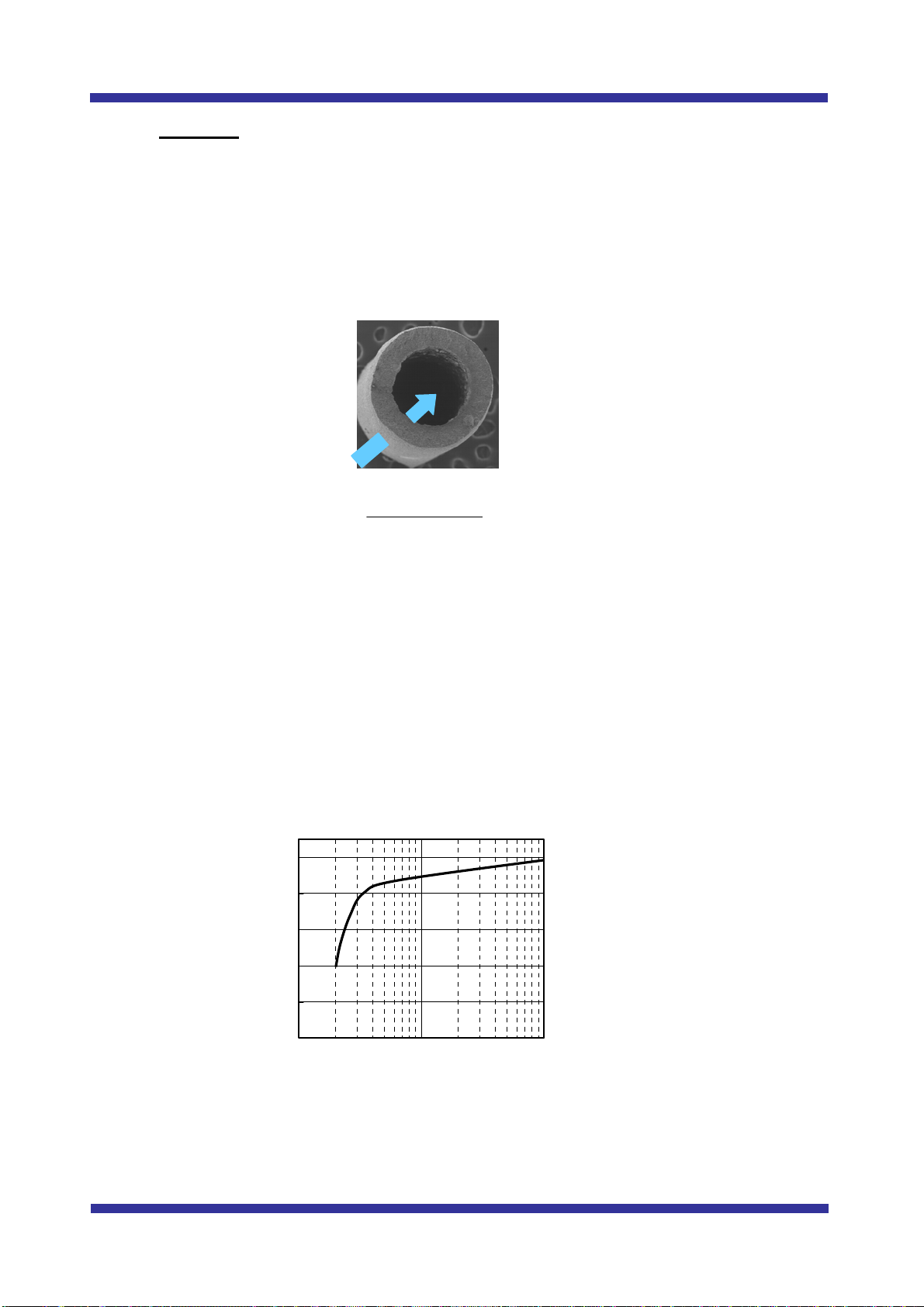
The hollow fiber membrane installed in this rack is made of PVDF (Polyvinylidene
fluoride). Cross section of the structure is shown in Fig. 1. Flow direction to the
hollow fiber membrane is outside to inside.
Fig. 1 Cross section picture of Toray PVDF hollow fiber
The diameter of the hollow fiber membrane is designed to be as follows:
For HSU-1515: Outside diameter is 1.4 mm. Inside diameter is 0.9 mm.
Molecular weight cut off (MWCO) of the HSU membrane is shown in Fig. 2. The
MWCO is determined by dextran solution having molecular weight of 70,000,
200,000 and 500,000. The concentrations of the dextran are measured by the
Refractive Index Detector.
0
20
40
60
80
100
10,000 100,000 1,000,000
MW of Dextran
Rejection (%)
Fig.2 Molecularweightcut off (MWCO) of the HSU membrane
Flow Direction
(Outside-in) Cross Section
Flow Direction
(Outside-in) Cross Section

11
The membrane is manufactured with special spinning method developed by
TORAY and the nature of the membrane surface is modified for high fouling
resistance. As a result, this membrane enables very high filtration flux compared to
other PVDF membranes. In addition, the physical strength of the membrane fiber is
so high that it hardly gets breakage during the normal operation for many years.
2. Outline of element
TORAY PVDF Hollow Fiber Membrane Element “HSU-1515” is submerged type
which is shown Fig. 3.
Effective membrane area of an element is as follows:
HSU-1515: 20 m2
HSU-1515: suitable for high turbidity water, large-scale water treatment plants.
Fig. 3 Picture of element (HSU-1515)

12
3. Outline of rack
“Rack” contains a number of membrane elements stacked at equal clearance and
two air diffusers. Each element is connected to the permeated water manifold.
The air diffuser consists of a number of holes to supply scouring air to each
membrane element.
This rack is used submerged in water to be treated.
Rack image is shown Fig. 4.
Fig. 4 Image of “Rack” (4 units of R16 Model are submerged in tank)
Permeate
Backwash
Feed
Air Drain
Drain
Permeate
Backwash
Feed
Air Drain
Drain

13
IV. Specifications and Configuration
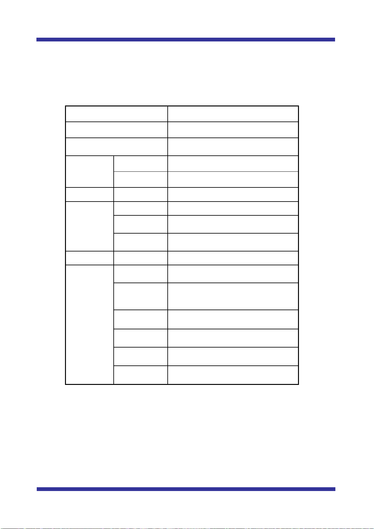
1. Specifications of Membrane
Table 1. Specifications of membrane *1)
Membrane Type HSU
Nominal Molecular Weight Cut Off 150,000 *2)
Membrane material PVDF
Filtrating
Trans-Membrane
Pressure
Maximum *3) 100 kPa
Normal Operation Not higher than 100 kPa
Backwashing
Trans-Membrane
Pressure
Maximum *4) 200 kPa
Normal Operation Not higher than 150 kPa
Storage and Operating
Temperature Range 0 - 40 degree C
Operating pH Range 1 – 10
*1): Please note that the specifications are subject to changes from time to time.
*2): The nominal molecular weight cut off is determined with the model test of dextran.
*3): TMP (
Trans-Membrane Pressure) should be below 100 kPa at any time even
during the filtration.
*4): TMP (Trans-Membrane Pressure) should be below 200 kPa at any time even
during the backwash.
14
2. Specifications and Configuration of Element
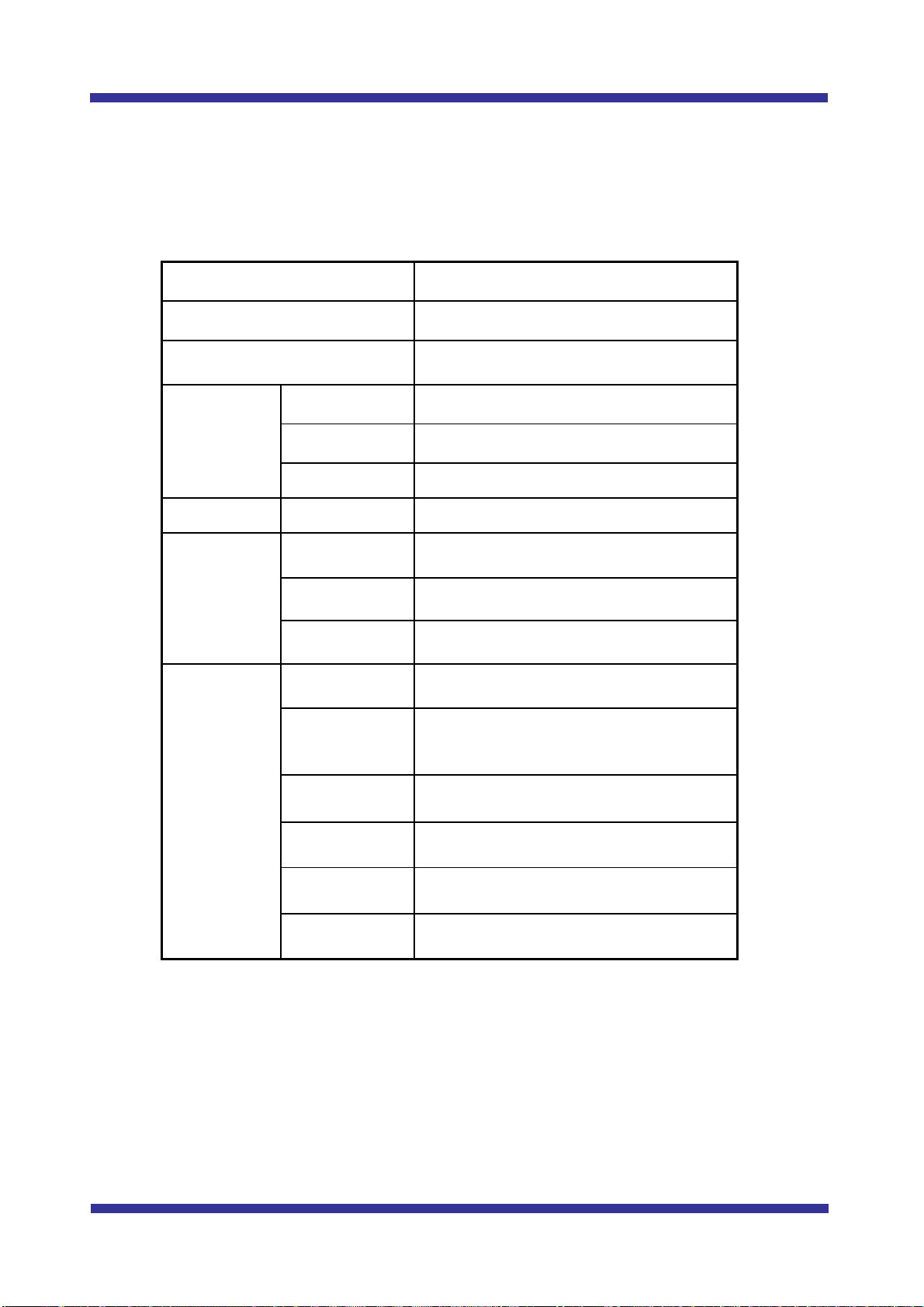
(1) Specifications of element
Table 2. Specifications of element *1)
Element Type HSU-1515
Membrane Type HSU
Membrane Surface Area
(Outer Surface) 20 m2
Dimensions Diameter 147 mm
Length 1,327 mm
Weight Wet Condition 18 kg
Materials
Cap ABS
Protective
Cylinder PE
Potting
Material Epoxy or equivalent
Connections Top Center IDF/ISO Clamp Union Fitting 1.5s
Operating
Conditions
Max. Feed
Water Flow 2.0 m3/h
Max.
Backwash
Flow 3.0 m3/h
Max. Air Flow 4.5 Nm3/h
Normal Air
Flow 1.5 – 3.0 Nm3/h
Filtration
Method Submerged, Outside to inside
Maximum
Temperature 40 degree C
*1): Please note that the specifications are subject to changes from time to time.

15
(2) Configuration of element
Fig. 5 Configuration of element
(a): Nozzle
(b): Nut
Connections
Pipe fitting
outer
diameter
mm
Connectors
(a) 50 IDF/ISO Clamp
Union Fitting 1.5s
Filtrate Outlet
(b)
Inlet of Backwash Water
(a)
Feed
Drain
Feed
Drain
Drain
Air
Feed
Air Air
Lowest Water Level
in Filtration
180
1327
156
Filtrate Outlet
(b)
Inlet of Backwash Water
(a)
Feed
Drain
Feed
Drain
Drain
Air
Feed
Air Air
Lowest Water Level
in Filtration
180
1327
156
180
1327
180
1327
156
16
3. Specifications and Configuration of Rack
(1) Specifications of Rack
Table 3. Specifications of Rack Module “R16“ *1)
No. of Elements / Rack 16 elements
Element Type HSU-1515
Total Membrane Area
(Outer Surface) 320 m2
Dimensions
Height 1,800 mm
Length 1,587 mm
Width 365 mm
Weight Wet Condition Max. 500 kg
Materials
Element PVDF, ABS, PE,
Epoxy or equivalent
Rack 304SS *2)
Pipe 304SS *2), PP, HIVP
Operating
Conditions
Max. Feed
Water Flow 32 m3/h
Max.
Backwash
Flow 48 m3/h
Max. Air Flow 72 Nm3/h
Normal Air
Flow 24 – 48 Nm3/h
Filtration
Method Submerged
Outside to inside
Maximum
Temperature 40 degree C
*1): Please note that the specifications are subject to changes from time to time.
*2): 316SS is available as option.

17
Table 4. Specifications of Rack Model “R08“ *1)
No. of Elements / Rack 8 elements
Element Type HSU-1515
Total Membrane Area
(Outer Surface) 160 m2
Dimensions
Height 1,800 mm
Length 851 mm
Width 365 mm
Weight Wet Condition Max. 250 kg
Materials
Element PVDF, ABS, PE,
Epoxy or equivalent
Rack 304SS *2)
Pipe 304 SS*2), PP, HIVP
Operating
Conditions
Max. Feed
Water Flow 16 m3/h
Max.
Backwash
Flow 24 m3/h
Max. Air Flow 36 Nm3/h
Normal Air
Flow 12 – 24 Nm3/h
Filtration
Method Submerged
Outside to inside
Maximum
Temperature 40 degree C
*1): Please note that the specifications are subject to changes from time to time.
*2): 316SS is available as option.

18
(2) Configuration
Rack Model “R16”
Table of contents
Other Toray Water Filtration System manuals


Popular Water Filtration System manuals by other brands

AquaScape
AquaScape SIGNATURE Series Instruction and maintenance

BWT
BWT bestaqua 14ROC Installation and operating instructions

Waterco
Waterco HYDROCHLOR ST owner's manual

HEISSNER
HEISSNER FPU10100-00 Instructions for use

Wateraid
Wateraid Smarttap User's manual & warranty information

cleansui
cleansui AJP407-D instruction manual


Davey
Davey EMX3600 Installation & operation instructions

Miltenyi Biotec
Miltenyi Biotec autoMACS Pro user manual

Matheson
Matheson 6124 instructions

AquaScape
AquaScape 77011 installation instructions

EHEIM
EHEIM aqua160 Original operating manual

ElectroMaax
ElectroMaax Marine Watermaker Series Installation, operation & maintenance manual