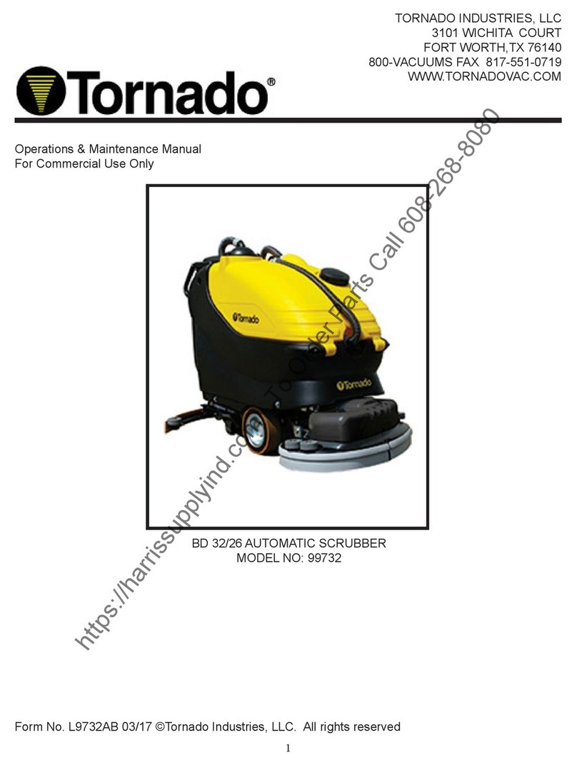
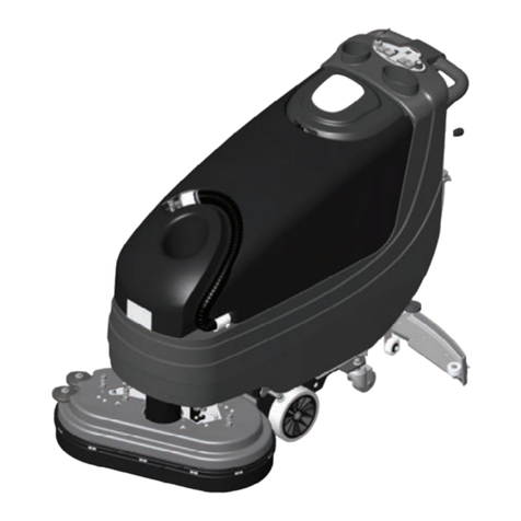
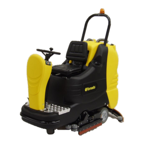
Tornado 99732 BD 32/26 Manual

Tornado Industries
333 Charles Ct.
Suite 109
West Chicago, Illinois 60185
1(800)-822-8864 Fax. #: 630-818-1301
www.tornadovac.com
Operations & Maintenance Manual
For Commercial Use Only
MODEL NO.
99732 BD 32/26
Tornado, LLC. All rights reserved – 11 2015


GB GB
3
SUMMARY
LEGEND INSTRUMENT BOARD AND CONTROLS 4
LEGEND MACHINE 4
OPTIONAL ACCESSORIES 5
TECHNICAL DESCRIPTION 5
INTRODUCTORY COMMENT 6
GENERAL RULES OF SECURITY 6
SYMBOLOGY 6
BEFORE USE 7
Handling of the packed machine 7
Unpacking of the machine 7
Access to the battery compartment 7
Battery installation and setting of the battery type 7
Battery recharger 7
On-board battery recharger (optional) 7
Batteries recharging 7
Batteries recharging with on-board battery recharger (optional) 8
Batteries disposal 8
Batteries charge level indicator 8
Hour meter 8
Squeegee assembly 8
Adjustment of the squeegee 8
Splash guard assembly 9
Brushes assembly 9
FLOOR CLEANING 9
Connection of the batteries to the machine 9
Recovery tank 9
Detergent solution tank 9
3S System “Solution Saving System” (optional) 10
Starting of the machine 10
Forward movement 10
Speed adjustment 10
Security device reverse movement 10
Working brake 10
Emergency brake 10
Adjustment of the brushes pressure 10
Brushes motor overload protection device 11
Overflow device 11
STOP OF THE MACHINE AFTER CLEANING OPERATION 11
DAILY MAINTENANCE 11
Recovery tank cleaning 11
Suction filter cleaning 11
Brushes cleaning 11
Brushes disassembly 11
Squeegee cleaning 12
WEEKLY MAINTENANCE 12
Rear squeegee rubber check 12
Squeegee “V” type (optional) 12
Squeegee “V” type (optional): rear rubber replacement 12
Squeegee hose cleaning 12
Cleaning of the solution tank 12
Cleaning of the solution filter 13
TWO-MONTHLY MAINTENANCE 13
Front squeegee rubber check 13
Squeegee “V” type (optional): front rubber replacement 13
SIX-MONTHLY MAINTENANCE 13
Splash guard rubber check 13
Cleaning of the inner filter solution tank 13
Check of the brake 13
TROUBLESHOOTING GUIDE 13
The suction motor does not work 13
The brushes motor does not work 13
The traction motor does not work 14
The detergent solution on the brushes is not sufficient 14
The machine does not clean properly 14
The squeegee does not dry perfectly 14
Excessive foam production 14
PROGRAMMED MAINTENANCE 14
RECOMMENDED BRUSHES 15

GB GB
4
LEGEND INSTRUMENT BOARD AND CONTROLS
1. DISPLAY
2. SWITCH SPEED SELECTION
3. SWITCH SUCTION MOTOR
4. SIGNAL LAMP BRAKE ON
5. SWITCH SOLENOID VALVE/COMMUTATOR 3S SYSTEM (OPTIONAL)
6. SWITCH BRUSHES MOTOR
7. PUSH BUTTON UP/DOWN BRUSHES BASE (only version with actuator)
8. PUSH BUTTON VISUALIZATION HOUR METER
9. SWITCH WITH KEY
10. INSTRUMENT BOARD
11. HANDLE BARS
12. LEVERS DRIVE CONTROL
13. PUSH BUTTON SECURITY DEVICE REVERSE MOTION
14. LEVER SOLUTION VALVE
15. LEVER BRUSHES BASE GROUP LIFTING (only version with hydraulic pump)
16. LEVER PARKING / EMERGENCY BRAKE
17. LEVER SQUEEGEE LIFTING
LEGEND MACHINE
1.
SOLUTION TANK
2.
RECOVERY TANK
3.
INSPECTION CAP RECOVERY TANK
4.
PLUG EXHAUST HOSE RECOVERY TANK
5.
COUPLING SQUEEGEE HOSE / RECOVERY TANK
6.
BLOCKING LEVERS SUCTION COVER
7.
SUCTION COVER
8.
SUCTION HOSE
9.
KEY SWITCH
10.
INSTRUMENT BOARD
11.
HANDLE BARS
12.LEVERS DRIVE CONTROL
13. PUSH BUTTON SECURITY DEVICE REVERSE MOTION
14. LEVER SOLUTION VALVE
15. LEVER BRUSHES BASE GROUP LIFTING (only version with hydraulic pump)
16. LEVER PARKING / EMERGENCY BRAKE
17. LEVER SQUEEGEE LIFTING
18. COUPLING SQUEEGEE HOSE / SQUEEGEE
19. SQUEEGEE ASSEMBLY
20. GUIDE SPRING SQUEEGEE HOSE
21. KNOB PRESSURE ADJUSTMENT BRUSHES BASE
22. CASTOR WHEELS
23. TRACTION WHEELS
24. BRUSHES BASE GROUP
25. SCREW CAP FOR INLET DETERGENT SOLUTION

GB GB
5
OPTIONAL ACCESSORIES
On-board battery charger.
Solution Saving System Assembly (3S).
Squeegee “V”-type.
TECHNICAL DESCRIPTION
U/M
BD 32 26
Cleaning width
mm/in
830/32
Squeegee width
mm/in
1070/42
Working capacity, up to
sqm/h, sqft/h
3750/40,364
Brushes diameter
mm/in
2x430/2x17
Brushes rpm
Rpm
160
Pressure on the brushes
kg/lbs.
60 max/133 max
Brushes motor
W/A
1100/46
Traction motor
W/A
400/13
Type of drive
autom.
Movement speed 1st speed
km/h/mph
3,5/3
Movement speed 2nd speed
km/h/mph
5,0/2
Maximum gradient
10 %
Suction motor
W/A
570/24
Suction vacuum
mbar/inches of water
160/64
Solution tank
l/gal
100/26
Recovery tank
l/gal
105/28
Machine length
mm/in
1695/67
Machine height
mm/in
1195/47
Machine width (without squeegee)
mm/in
895/35
Capacity of the batteries
V/Ah5h
24/240
Weight of the batteries
kg/lbs.
190/419
Compartment of the batteries
mm/in
415x520x385/
16.5x20.5x15
Weight of the machine (empty and without batteries)
kg/lbs.
195/430
Acoustic pressure level
dB (A)
-
Level of vibration right hand
m/sqs
-
Level of vibration left hand
m/sqs
-
Max. level of the electromagnetic field
µT
-
Class
III
Protection level
IP
X3
Tension
V
24

GB GB
6
INTRODUCTORY COMMENT
Thank you for having chosen our machine. This floor
cleaning machine is used for the industrial and civil
cleaning and is able to clean any type of floor. Dur-
ing its advance movement, the combined action of
the brushes and the detergent solution removes the
dirt which is aspirated through the rear suction as-
sembly, giving a perfectly dry surface.
The machine must be used only for such purpose. It
gives the best performance if it is used correctly and
maintained in perfect efficiency. We therefore ask
you to read this instruction booklet carefully when-
ever difficulties arise in the course of the machine’s
use. In case of need, we ask you to contact our ser-
vice department for all advice and servicing as may
prove necessary.
GENERAL RULES OF SECURITY
The rules below have to be followed carefully in or-
der to avoid damages to the operator and to the ma-
chine.
- Read the labels carefully on the machine. Do not
cover them for any reason and replace them imme-
diately if damaged.
- The machine must be used exclusively by author-
ized staff that has been instructed for its use.
- During the working of the machine, pay attention
to other people and especially to the children.
- In case of danger act immediately upon the emer-
gency brake.
- Leaving the machine in parking position, take off
the key and act upon the parking brake.
- Do not mix different detergents, avoiding harmful
odours.
- Do not place any liquid containers onto the ma-
chine.
- Storage temperature: between -25°C and +55°C
(-13°F and 131°F).
- Perfect operating temperature: between 0°C and
40°C (32°F and 104°F).
- The humidity should be between 30 and 95%.
- Do not use the machine in explosive atmosphere.
- Do not use the machine as a means of transport.
- Do not use acid solutions in such concentrations
that could damage the machine and/or the persons.
- Do not use the machine on surfaces covered with
inflammable liquids or dusts (for example hydrocar-
bons, ashes or soot).
- In case of fire, use a powder fire-extinguisher.
Do not use water.
- Do not strike shelvings or scaffoldings, where there
is danger of falling objects.
- Adapt the working speed to the adhesion condi-
tions.
- Do not use the machine on areas having a higher
gradient than the one stated on the number plate.
- The machine has to carry out simultaneously the
operations of washing and drying. Different opera-
tions must be carried out in restricted areas prohib-
ited to non-authorized personnel. Signal the areas of
moist floors with suitable signs.
- If the machine does not work properly, check by
conducting simple maintenance procedures. Other-
wise, ask for technical advice to an authorized assis-
tance centre.
- Where parts are required, ask for ORIGINAL spare
parts to the distributor and/or to an authorized deal-
er.
- Use only ORIGINAL brushes indicated in the para-
graph “RECOMMENDED BRUSHES ".
- For any cleaning and/or maintenance operation
take off the power supply from the machine.
- Do not take off the protections which require the
use of tools to be removed.
- Do not wash the machine with direct water jets or
with high water pressure nor with corrosive material.
- Every 200 working hours have a machine check
through an authorized service department.
- In order to avoid scales on the solution tank filter,
do not fill the detergent solution many hours before
the machines’ use.
- Before using the machine, check that all panels
and coverings are in their position as indicated in
this use and maintenance catalogue.
- Be sure the recovery tank is empty before lifting it.
- Restore all electrical connections after any mainte-
nance operation.
- Provide for the scrapping of the material of normal
wear following strictly the respective rules.
- When your machine has to stop activity, provide
for the appropriate waste disposal of its materials,
especially oils, batteries and electronic components,
and considering that the machine itself has been,
where possible, constructed using recyclable materi-
als.
SYMBOLOGY
Symbol denoting the solution
valve.
Indicates the solution valve lever.
Indicates the switch of the
solenoid valve.
Symbol denoting the brush.
Indicates the switch of the
brushes motor.
Symbol denoting the suction
motor.
Indicates the switch of
the suction
motor.
Symbol denoting up – down of
the squeegee.
Indicates the squeegee lever.
Symbol denoting the selection
switch of the driving speed.
Symbol that indicates the lever
for the brushes base lifting or the
push button up/down brushes
base.
Symbol denoting the charge level
of the batteries.
Symbol denoting the hour
meter.
Indication of the maximum
temperature of the solution
detergent.
It is placed near the charging
hole of the solution tank.
Symbol denoting the brake.
Indicates the signal lamp of the
brake on.
Symbol denoting the brake.
Indicates the lever of the
emergency and parking brake.
Symbol denoting the crossed
bin. Indicates that at the end of
its activity, the machine has to
be disposed conforming to the
laws in force.
Symbol denoting the open book.
Indicates that the operator has
to read the manual before the
use of the machine.
Warning symbol.
Read carefully the sections
marked with this symbol, for the
security of both the operator
and the machine.

GB GB
7
BEFORE USE
HANDLING OF THE PACKED MACHINE
The machine is supplied with suitable packing fore-
seen for fork lift truck handling.
The total weight is 562 lbs. (255kg)
Packing dimensions:
Base: 70” (178 cm) x 37” (93 cm)
Height: 54” (138 cm)
ATTENTION:
Do not place more than 2 packings on top of each
other.
UNPACKING OF THE MACHINE
1. Remove the external packing.
2. Unscrew the brackets (1+2) that secure the ma-
chine to the pallet.
3. Move the machine backwards, avoiding heavy
contacts to mechanical parts.
4. Keep the pallet and the brackets for eventual
transport.
ACCESS TO THE BATTERY COMPARTMENT
In order to reach the battery compartment, it is nec-
essary to rotate forwards the recovery tank (1).
Before rotating it, it is necessary to:
1. Bring the machine on a levelled surface.
2. Take off the squeegee hose (2) from its seat.
3. Take off the suction cover (4) after turning the
blocking levers (3).
4. Verify by lifting the filter and its protection, that
the tank is empty, otherwise, proceed to the empty-
ing as indicated under paragraph “RECOVERY TANK
CLEANING”.
5. Rotate, lifting lightly the tank from its rear han-
dle until the gas shock absorber (1) acts, which lifts
it up to a first position. Lifting it more, the maximum
opening can be obtained.
6. Having finished any type of intervention, close
the battery compartment pushing the tank down-
wards if it is open at the first position, while from
the maximum opening it is necessary to unblock the
support of the gas shock absorber (1).
7. Reassemble everything.
BATTERY INSTALLATION AND SETTING OF THE
BATTERY TYPE
The machine is equipped either with batteries in se-
rial connection or elements of DIN-type assembled
together and connected in series, placed in its ap-
propriate compartment under the recovery tank and
must be handled using suitable lifting equipment
(due to weight, considering the type of batteries
chosen, and coupling system).
The batteries must be in accordance with CEI 21-5
Norms.
The machines at 24V will fit the batteries into the
appropriate reduced steel basin.
ATTENTION:
The machine and its battery check card foresee the
use of traditional lead batteries.
CHECK SETTING OF THE CHECK CARD ON THE INDI-
CATOR (1) (see under paragraph "BATTERIES CHARGE
LEVEL INDICATOR").
In case of GEL batteries installation, it is necessary to
set the battery check card. Please contact the autho-
rized technical assistance.
ATTENTION:
Strictly follow manufacturer/distributor indications
for the maintenance and recharge of the batteries.
All installation and maintenance operations must be
executed by specialized staff, using suitable protec-
tion accessories.
For batteries installation it is necessary to reach the
battery compartment as indicated under paragraph
“ACCESS TO THE BATTERY COMPARTMENT”.
1. Rotate the recovery tank up to the maximum
opening position.
2. Place the batteries in its compartment.
3. Connect the terminals, respecting the polari-
ties, avoiding contact with other parts that could
create short circuit.
BATTERY RECHARGER
Be sure that the battery recharger is suitable for
the installed batteries both for their capacities
and type (lead/acid or GEL and equivalent).
In the plastic bag containing the use and mainte-
nance you will find the coupling connector for the
recharger. It must be assembled onto the cables of
your recharger, following the instructions given by
the manufacturer.
ATTENTION:
This operation must be carried out by qualified staff.
A wrong or faulty cable connection can cause seri-
ous damages to persons or things.
ON-BOARD BATTERY RECHARGER (OPTIONAL)
If the machine is equipped with the on-board bat-
tery recharger (see under "OPTIONAL ACCESSORIES”)
please refer to the instructions of the constructor of
this accessory what the recharging operations con-
cern.
The battery recharger is connected directly to the
battery poles.
During the recharging operations a device is activat-
ed which does not permit the machine's functioning.
The mains cable of the battery recharger has a max-
imum length of two metres and must be connected
to a single-phase socket type CEE 7/7.
BATTERIES RECHARGING
For batteries recharge it is necessary to reach the
battery compartment as indicated under paragraph
“ACCESS TO THE BATTERY COMPARTMENT”.

GB GB
8
1. Plug in the batteries connector (1) placed in the
inner part of the machine, to the connector (3) of
the battery recharger.
2. Proceed to the recharging keeping the tank lifted.
3. Maintain the connection with the battery re-
charger until the indication of the end of charge is
not visualized.
BATTERIES RECHARGING WITH ON-BOARD BAT-
TERY RECHARGER (OPTIONAL)
Bring the machine on a levelled surface near to a
single-phase socket with tension 230V, frequency
50Hz, nominal current 10A.
Switch off the switches of the brushes motor, suc-
tion motor and of the solenoid valve.
1. Insert the plug into the mains socket.
2. Proceed to the recharging keeping the tank lifted
(see under paragraph “ACCESS TO THE BATTERY
COMPARTMENT” in “BEFORE USE”).
3. Do not take off the plug from the mains socket
until the indication of the end of charge is not visu-
alized.
At the end of the recharging, take off the plug from
the mains socket.
ATTENTION:
Never charge a GEL battery with a non suitable
recharger. Strictly follow the instructions sup-
plied by the batteries and recharger manufactur-
er.
In order not to cause permanent damages to the
batteries, it is necessary to avoid their complete dis-
charge, providing for the recharging within a few
minutes after that the batteries discharge signal
starts blinking.
NOTE: Never leave batteries completely discharged
even if the machine is not used. In case of traditional
batteries, please check the electrolyte level every 20
recharging cycles and eventually top them up with
distilled water.
ATTENTION:
For the recharge of the batteries it is necessary to
follow strictly all the indications given by the manu-
facturer/distributor. All the installation and mainte-
nance operations must be carried out by qualified
staff. Danger of gas exhalations and emission of
corrosive liquids. Fire danger: do not approach
with free flames.
BATTERIES DISPOSAL
It is compulsory to hand over exhausted batteries,
classified as dangerous waste, to an authorized insti-
tution according to the current laws.
BATTERIES CHARGE LEVEL INDICATOR
TURNING THE KEY (9) CLOCKWISE, ON THE DISPLAY
(1) APPEAR IN SEQUENCE THE FOLLOWING INFOR-
MATION:
1. the version (for example A003) of software in-
stalled on the machine.
2. the setting of the battery check card is for the
24V version:
GE 24: check card set for GEL batteries
Pb 24: check card set for lead batteries
3. The batteries charge level indicator (1) is digital.
The battery charge level starts at 90, which indicates
the 90% of the total charge and decreases from 10
to 10. When the charge level reaches 20%, the dis-
play starts blinking, so you are about the end of
working.
ATTENTION:
After a few seconds from the blinking of the four
lines, the brushes motor stops automatically. With
the remaining charge it is anyhow possible to finish
the drying operation before proceeding to the re-
charge.
HOUR METER
The machine is equipped with an hour meter located
on the same display of the battery charge level indi-
cator (1). Keeping the button (8) pressed for more
than 3 seconds, the first data indicates the working
hours and after a few seconds the working minutes
are shown.
SQUEEGEE ASSEMBLY
1. Maintain the squeegee support (1) slightly lifted
from the floor.
2. Insert the two stud bolts (3) placed on the upper
part of the squeegee (2) inside the slots on the sup-
port.
3. Block the squeegee by rotating the lever (4)
clockwise.
4. Insert the squeegee hose (5) into its coupling, re-
specting its position as indicated in the figure.
ADJUSTMENT OF THE SQUEEGEE
In order to have a perfect drying result through the
squeegee, the rear rubber must have the lower bend-
ing uniformly adjusted in all its length. For the ad-
justment, it is necessary to put oneself in working
condition and therefore the suction motor has to be
switched on and the brushes have to function to-
gether with the detergent solution.
The lower part of the rubber is too much bent
Take off the pressure rotating the wing nut (6) coun-
terclockwise.
The lower part of the rubber is not much bent
Increase the pressure rotating the wing nut (6)
clockwise.
The bending is not uniform
Adjust the squeegee inclination rotating counter-
clockwise the wing nut (7) to increase the bending in
the central part, or clockwise to increase the bending
on the extremities.
Height adjustment
Once that the pressure and inclination of the squee-
gee has been adjusted, it is necessary to fix this op-
timum condition making touch slightly the wheels
0.19”

GB GB
9
onto the floor. Rotate counterclockwise the registers
(8) to lower the wheels or clockwise to raise them.
Both wheels must be adjusted in the same measure.
ATTENTION:
Every type of floor requires a specific adjustment.
For example, concrete floors (where the friction re-
sults to be high) need little pressure, while smooth
floors (ceramics) need higher pressure.
If the cleaning operations are made always on the
same type of floor, the adjustment can change only
in function of the rubber wear.
SPLASH GUARD ASSEMBLY
The two splash guards have to be assembled onto the
brushes base group. Insert the metal strips inside the
suitable slots present on the rubber. Place the round
hole at the flat extremity of the strip onto the screw
(1) placed in the front part of the brushes base
group. Secure the strips through the nut blocking it.
Block the coupling levers (2) in the rear part of the
brushes base group to the rings placed at the ex-
tremity of the metal strips still free. Please act as
above for both splash guard rubbers, paying atten-
tion to reduce to the minimum the gap between the
two rubbers in the front part of the brushes base
group.
With brushes assembled, the splash guard must
slightly touch the floor.
BRUSHES ASSEMBLY
The machines which have the electrical brushes base
lifting:
1. Switch on the machine by turning the key (9)
clockwise.
2. Press the push button (7) of up/down brushes
base to lift the brushes.
3. Take off the electric supply by turning the key (9)
counterclockwise.
ATTENTION:
To carry out brushes assembly operations with the
electric supply on, may cause damages to hands.
With the brushes base group in lifted position, insert
the brushes into their plate seat underneath the
brushes base turning them until the three metal but-
tons are properly seated in their slots; rotate ener-
getically the brushes to push the button towards the
coupling spring until they get blocked.
The figure shows the rotating sense for brushes cou-
pling.
For a longer life of the brushes we suggest to invert
daily their position. Whenever brushes were de-
formed we suggest to reassemble them in the same
position, avoiding that the different inclination of
the bristles causes excessive motor overload or trou-
blesome vibrations.
ATTENTION:
Use only brushes supplied with the machine or the
ones indicated in the paragraph “RECOMMENDED
BRUSHES”. The use of other brushes can compromise
security.
FLOOR CLEANING
CONNECTION OF THE BATTERIES TO THE MA-
CHINE
Once that the battery recharging has been complet-
ed:
1. Disconnect the connector (3) of the battery re-
charger (1). To do this, it is necessary to reach the
battery compartment as indicated under paragraph
“ACCESS TO THE BATTERY COMPARTMENT”.
2. Connect instead the machine connector (2).
3. Close the battery compartment.
RECOVERY TANK
Check that the cover of the suction filter (1) is cor-
rectly secured, after rotating the levers (2) and that
the suction motor hose (3) is correctly connected to
it.
Verify also that the squeegee hose couplings (4) are
correctly inserted into the seats, that the exhaust
hose plug (5) placed in the front part of the machine
is closed and that also the inspection cap (6) is
closed well.
DETERGENT SOLUTION TANK
The capacity of the detergent solution tank is indi-
cated in the technical data.
Open the screw plug placed in the rear left part of
the machine and fill the detergent solution tank
with clean water at a maximum temperature of 50°C.
Add the liquid detergent in the percentage and con-
ditions foreseen by the manufacturer. To avoid ex-
cessive foam presence, which could cause problems
to the suction motor, use the minimum percentage
of detergent. Screw down the plug to close the tank.

GB GB
10
ATTENTION:
Use always low foam detergent. To avoid foam pres-
ence, before starting working operation, introduce
into the recovery tank a minimum quantity of anti-
foam product.
Never use pure acid.
3S SYSTEM “SOLUTION SAVING SYSTEM” (OP-
TIONAL)
The need of an increasing carefulness to the envi-
ronment, and to the abuse of polluting elements,
such as detergents in the floor cleaning machines,
has brought us to the realization of a device which,
regardless from the capacity to use the machine by
the operator, keeps the minimum flow of the deter-
gent solution constant, having been properly cali-
brated by an expert technician. The best detergent
solution amount with this system will be the one
which realizes the minimum flow of detergent solu-
tion sufficient to clean correctly the floor. For this
reason the system is called “Solution Saving System”
abbreviated to “3S” system.
The system is composed by a hydraulic circuit paral-
lel to the traditional one which can be enabled or
disabled directly from the instrument board through
a 3-position switch with the following functions:
(1) = Position solution valve with traditional func-
tioning with variable water flow that differs by the
opening of the solution valve.
(2) = Position STOP with functioning without flow
(drying only).
(3) = Position 3S with functioning with optimal
fixed flow.
STARTING OF THE MACHINE
1. Turn the key (9) clockwise.
2. Check the battery type and the charge level on
the display (1).
3. Press the brushes motor switch (6).
4. Press the suction motor switch (3).
5. Press the solenoid valve switch (5).
6. Lower the brushes base onto the floor.
The machines which have the electrical brushes base
lifting press the push button (7) of up/down of the
brushes base.
7. Acting upon the solution valve lever (14) open
and adjust the detergent solution flow.
The water starts to flow automatically acting upon
the levers drive control (12). On the instrument
board the indicator of the solenoid valve switch (5)
will turn on. Releasing these levers, the flow will stop.
Models equipped with the 3S system (optional), it is
necessary to press the suitable switch to activate the
detergent solution supply by choosing between the
traditional adjustment system through the solution
valve or the system of fixed optimum supply (see
under “3S SYSTEM SOLUTION SAVING SYSTEM”).
8. Acting upon the squeegee lifting lever (17) lower
the squeegee.
9. Acting upon the levers drive control (12) the ma-
chine starts to move, the brushes start to rotate and
the squeegee starts to dry.
10. During the first metres check that the squeegee
adjustment guarantees a perfect drying action and
that the detergent solution flow is appropriate. It
has to be sufficient to wet the floor uniformly avoid-
ing the leakage of detergent from the splash guards.
Always consider that the correct quantity of solution
detergent depends on type of floor, dirtiness and
machine speed.
FORWARD MOVEMENT
The traction of the machine is given through an
electronically controlled motor.
To move the machine, act upon the key (9) and then
rotate the levers drive control (12) placed on the
handle bar, in forward you obtain the forward drive,
in reverse the backwards movement is obtained. The
control acts in a progressive way, therefore it is pos-
sible to graduate the speed depending on each re-
quirement rotating the lever whatever it is necessary.
During reverse motion the speed is reduced.
SPEED ADJUSTMENT
Two values of the maximum drive working speed in
forward movement can be chosen.
Set the wanted speed through the speed selection
switch (2).
ATTENTION:
Moving the machine backwards, make sure that the
squeegee is lifted.
SECURITY DEVICE REVERSE MOVEMENT
A large-sized push button (13), placed on the rear
extremity of the machine is for the automatic drive
inversion. If the operator unintentionally remains
blocked between the machine and an obstacle, this
push button gives the control to invert the machine
when it touches the operator.
WORKING BRAKE
To stop the machine during normal working situa-
tion, it is sufficient to release the levers drive control
(12), as the machine is equipped with an electronic
braking system. The brushes and the detergent solu-
tion flow stop automatically.
EMERGENCY BRAKE
In case of an emergency, an immediate stop can be
obtained acting upon the lever of the emergency
and parking brake (16) by pushing it downwards.
ATTENTION:
This control blocks the machine immediately. The
emergency brake functions also as a parking brake.
To start again to work, release the lever by unblock-
ing the parking button on the lever itself and act
again upon the levers drive control (12).
ADJUSTMENT OF THE BRUSHES PRESSURE
Through the register (1) it is possible to adjust the
brushes pressure on the cleaned surface.
By turning the knob clockwise the pressure increases,
rotating it counterclockwise, the pressure decreases.
This device allows a more efficient cleaning action
also on very difficult and dirty surfaces.
The control of the adjustment value of the set pres-
sure is possible through a sliding indication. Its posi-
tion shows the value indicated on the label placed in
correspondence of the slots where it slides.
On the 24 Volt machines the indicator is placed in
the rear part of the frame inside the battery com-
partment.
GB GB
11
ATTENTION:
In order not to overload the brushes motor, it is con-
venient to reduce the brushes pressure going from
smooth floors to rough ones (ex. concrete).
BRUSHES MOTOR OVERLOAD PROTECTION DE-
VICE
The machine is equipped with a protection device of
the brushes motor. This device blocks the motor
functioning in order to protect it and indicates the
overload on the display (1) with ”AL01”. The block
could be caused by an excessive brushes pressure on
a rough floor. Check the brushes pressure adjust-
ment as indicated in the previous paragraph.
ATTENTION:
To restore the functioning of the brushes motor,
turn off and on again the machine acting upon
the key switch (9).
OVERFLOW DEVICE
In order to avoid serious damages to the suction mo-
tor, the machine is equipped with a float that inter-
venes when the recovery tank is full, closing the suc-
tion hose and stopping the suction.
When this happens, it is necessary to empty the re-
covery tank.
1. Hold the exhaust hose placed in the front part of
the machine.
2. Take off the exhaust plug acting upon its lever
and empty the recovery tank into appropriate con-
tainers, according to the standard norms.
ATTENTION:
This operation must be carried out using gloves to
protect from contact with dangerous solutions.
STOP OF THE MACHINE AFTER
CLEANING OPERATION
Before executing any type of maintenance:
1. Turn the brushes motor switch off (6).
2. Turn the suction motor switch off (3).
3. Lift the brushes base from the floor.
The machines which have the brushes base lifting
electrically done press the push button (7) of
up/down of the brushes base.
4. Lift the squeegee acting upon the lever (17).
5. Bring the machine to an appropriate place for
tanks draining.
6. Turn the key (9) counterclockwise.
7. Insert the parking brake (16).
DAILY MAINTENANCE
RECOVERY TANK CLEANING
1. Hold the exhaust hose placed in the front part of
the machine.
2. Take off the plug of the exhaust hose acting up-
on its lever and empty the recovery tank into appro-
priate containers.
3. Take off suction cover after rotating the blocking
levers.
4. Take off the filter and filter protection.
5. Take off the inspection cap of the recovery tank.
6. Rinse the tank with a water jet from both open-
ings.
ATTENTION:
This operation must be carried out using gloves to
protect from contact with dangerous solutions.
SUCTION FILTER CLEANING
1. Take off suction cover (2) after rotating the
blocking levers (1).
2. Take off the filter and filter protection.
3. Clean all parts with a water jet especially the in-
side surfaces and the filter bottom.
4. Carry out cleaning operations carefully.
5. Reassemble all parts.
BRUSHES CLEANING
Disassemble the brushes and clean them with a wa-
ter jet (check under paragraph of “BRUSHES DISAS-
SEMBLY”).
BRUSHES DISASSEMBLY
The machines which have the electrical brushes base
lifting:
1. Switch on the machine by turning the key (9)
clockwise.
2. Press the push button (7) of up/down brushes
base to lift the brushes.
3. Take off the electric supply by turning the key (9)
counterclockwise.

GB GB
12
ATTENTION:
To carry out brushes disassembly operations with the
electric supply on, may cause damages to hands.
With the brushes base in lifted position, turn the
brush in its rotating sense as indicated in the figure,
until it is released from the brush holder plate seat.
The figure shows the rotating sense for brushes rele-
ase.
ATTENTION:
Pick up the brushes and wash them using gloves to
protect from contact with dangerous solutions.
SQUEEGEE CLEANING
Keeping the squeegee clean guarantees always the
best drying action.
For its cleaning it is necessary to:
1. Take off the squeegee hose (5) from the coupling.
2. Disassemble the squeegee (2) from its support (1)
by rotating the lever (4) counterclockwise and mak-
ing slide the stud bolts (3) in their slots up to their
release.
3. Clean with care the internal part of the squeegee
inlet eliminating eventual dirt residuals.
4. Clean with care the squeegee rubbers.
5. Reassemble all parts.
WEEKLY MAINTENANCE
REAR SQUEEGEE RUBBER CHECK
Check the squeegee rubber wear and eventually turn
or replace it.
For the replacement it is necessary to:
1. Lift the squeegee acting upon the lever (17).
2. Release the hook (9) of the rubber holder blade
and take the rubber off.
3. Turn the rubber to a new side or replace it.
To reassemble the squeegee repeat reverse the oper-
ations above mentioned, inserting the rubber on the
guides and blocking it with the rubber holder blade.
SQUEEGEE “V” TYPE (OPTIONAL)
Alternatively to the standard squeegee, a “V”-shaped
squeegee is available, especially indicated for floors
with large joints.
This squeegee is interchangeable with the standard
one, same assembly on the machine, same adjust-
ment in height, pressure and inclination.
Different though are the methods in assembly and
disassembly of the squeegee rubbers.
SQUEEGEE “V” TYPE (OPTIONAL): REAR RUBBER
REPLACEMENT
Check the squeegee rubber wear and eventually turn
or replace it.
For the replacement it is necessary to:
1. Lift the squeegee through the lever (17).
2. Unscrew the tie rods (1) on the terminals (2) of
the rubber holder blade and disengage the terminals.
3. Unscrew the wing nuts (3) and take off the rub-
ber holder blade (4).
4. Turn the rubber (5) to a new side or replace it.
To reassemble the squeegee repeat reverse the oper-
ations above mentioned, inserting first the rubber (5)
into its guides, then positioning the rubber holder
blade and finally screwing down all wing nuts and
the tie rods of the two terminals.
SQUEEGEE HOSE CLEANING
Weekly or in case of insufficient suction, it is neces-
sary to check that the squeegee hose is not obstruct-
ed. Eventually, to clean it, proceed as follows:
1. Take off the hose (1) from the squeegee coupling.
2. Wash the inside of the hose with a water jet.
To reassemble the hose repeat reverse the operations
above-mentioned.
ATTENTION:
Do not wash the hose that goes from the suction
motor to the suction cover.
CLEANING OF THE SOLUTION TANK
1. Bring the machine to an appropriate place for
the detergent solution draining.
2. Unscrew the solution tank cap.
3. Unscrew the cap of the exhaust filter (1) so that
the detergent solution flows out into appropriate
containers. Pay attention not to lose the gasket of
the cap.
4. Rinse with a water jet the solution tank.
5. Reassemble all parts.

GB GB
13
ATTENTION:
This operation must be carried out using gloves to
protect from contact with dangerous solutions.
CLEANING OF THE SOLUTION FILTER
1. Empty the detergent solution tank as indicated in
paragraph “CLEANING OF THE SOLUTION TANK”.
2. Unscrew the cap of the exhaust filter (1).
3. Rinse the filter placed inside the cap, paying at-
tention not to lose the gasket of the cap.
4. Rinse the hose pouring some water into the solu-
tion tank.
5. Reassemble all parts.
ATTENTION:
This operation must be carried out using gloves to
protect from contact with dangerous solutions.
TWO-MONTHLY MAINTENANCE
FRONT SQUEEGEE RUBBER CHECK
Check the wear of the squeegee rubber and eventu-
ally replace it.
For the replacement it is necessary to:
1. Release the squeegee from the support as indi-
cated in paragraph "SQUEEGEE CLEANING".
2. Unscrew the wing nuts in the front part of the
squeegee.
3. Take off the rubber holder blade.
4. Replace the front rubber.
5. Reassemble all parts.
SQUEEGEE “V” TYPE (OPTIONAL): FRONT RUBBER
REPLACEMENT
Check the squeegee rubber wear and eventually re-
place it.
For the replacement it is necessary to:
1. Disassemble the squeegee from the support as
indicated under “SQUEEGEE CLEANING”.
2. Unscrew the tie rods (1) on the terminals (2) of
the rubber holder blade and disengage the terminals.
3. Unscrew all wing nuts (6) and take off the rubber
holder blade (7).
4. Take off the rubber (8) and replace it.
To reassemble the squeegee repeat reverse the oper-
ations above mentioned, inserting first the rubber (8)
into its guides, then positioning the rubber holder
blade and finally screwing down all wing nuts and
the tie rods of the two terminals.
SIX-MONTHLY MAINTENANCE
SPLASH GUARD RUBBER CHECK
1. Open the hooks in the rear part of the brushes
base group from the slot placed at the extremity of
the metal strip.
2. Replace the splash guard rubbers and follow as-
sembling instructions as under paragraph “SPLASH
GUARD ASSEMBLY”.
With brushes assembled, the splash guard must
slightly touch the floor.
CLEANING OF THE INNER FILTER SOLUTION TANK
Clean regularly the internal filter of the solution
tank which is in the rear low part of the machine.
Empty the solution tank, remove the fitting of the
water outlet by taking off the two screws which fix
it to the tank. Clean the inside filtrating part of the
fitting from eventual dirt. Pour some water into the
tank to clean it. Reassemble the fitting onto the so-
lution tank.
CHECK OF THE BRAKE
Check the braking efficacy and that both pads (1)
which act upon the traction wheels, in resting posi-
tion, have got a distance of not more than 3mm
from the wheels. If necessary, adjust them through
the fixing nuts (2).
The checking of all the other foreseen machine
operations is left to the authorized technical as-
sistance.
TROUBLESHOOTING GUIDE
THE SUCTION MOTOR DOES NOT WORK
1. Verify that the key switch (9) is in the correct po-
sition.
2. Check the charge level of the batteries on the
display (1).
3. Check that the battery connector is correctly
plugged in.
4. Verify that the switch (3) is on.
5. Check that the red connector of the suction mo-
tor is correctly plugged in.
If the problem persists, please contact the authorized
technical assistance.
THE BRUSHES MOTOR DOES NOT WORK
1. Verify that the key switch (9) is in the correct po-
sition. Switch off and on again the machine.
2. Check the charge level of the batteries on the
display (1).
3. Check that the battery connector is correctly
plugged in.
4. Verify that the switch (6) is on.
5. Act upon the levers drive control (12).
6. Check that on the display (1) does not appear the
alarm “AL01” (brushes motor overload alarm).
If the problem persists, please contact the authorized
technical assistance.

GB GB
14
THE TRACTION MOTOR DOES NOT WORK
1. Switch off and on again the machine.
2. Release the brake (16) until the signal lamp (4)
comes off.
3. Act upon the levers drive control (12).
If the problem persists, please contact the authorized
technical assistance.
ATTENTION:
Never leave the batteries discharged for a long time.
THE DETERGENT SOLUTION ON THE BRUSHES IS
NOT SUFFICIENT
1. Check that the solution valve lever (14) is open.
2. Check the level of the liquid in the solution tank.
3. Check that solution filter is clean (see under par-
agraph “CLEANING OF THE SOLUTION FILTER”).
4. The machine is equipped with solenoid valve,
therefore act upon the levers drive control (12) to let
come down the detergent solution and check that
the signal lamp (5) comes on.
5. If the machine is equipped with the 3S system
(see under “3S SYSTEM SOLUTION SAVING SYSTEM”)
(optional), check that the switch of the detergent
solution supply is activated by choosing between the
traditional adjustment system through the solution
valve or the system of fixed optimum supply.
6. If the detergent solution still does not come
down, clean the filter inside the solution tank. Empty
the solution tank, remove the fitting of the water
outlet by taking off the two screws which fix it to
the tank. Clean the inside filtrating part of the fit-
ting from eventual dirt. Pour some water into the
tank and clean it. Reassemble the fitting onto the
solution tank.
If the problem persists, please contact the authorized
technical assistance.
THE MACHINE DOES NOT CLEAN PROPERLY
1. The brushes do not have the suitable bristle di-
mension: contact the authorized technical assistance.
2. The brushes have got worn bristles. Check the
brushes wear condition and eventually replace them
(the brushes have to be replaced when the bristles
have reached a height of about ½”/15mm).
To replace brushes, see instructions at paragraph
“BRUSHES DISASSEMBLY” and “BRUSHES ASSEMBLY”.
3. The detergent solution is insufficient: open more
the solution valve.
4. Check that the liquid detergent is in the recom-
mended percentage.
5. Increase the brushes base pressure (see at para-
graph "ADJUSTMENT OF THE BRUSHES PRESSURE").
Contact the authorized technical assistance for ad-
vice.
THE SQUEEGEE DOES NOT DRY PERFECTLY
1. Check that the squeegee rubbers are clean.
2. Check the adjustment of the height and the in-
clination of the squeegee (see section “ADJUSTMENT
OF THE SQUEEGEE” in “BEFORE USE”).
3. Check that the suction hose is correctly inserted
in the proper seat on the recovery tank.
4. Clean the suction filter.
5. Replace the rubbers if worn out.
6. Check that the suction motor switch is on.
EXCESSIVE FOAM PRODUCTION
Check that low foam detergent has been used. Even-
tually add small quantities of anti foam liquid into
the recovery tank.
Please be aware that a bigger quantity of foam is
produced when the floor is not very dirty. In this ca-
se please dilute detergent solution.
PROGRAMMED MAINTENANCE
INTERVENTION
DAILY
20 HOURS *
200 HOURS *
1000 HOURS *
RECOVERY TANK CLEANING
•
SUCTION FILTER CLEANING
•
SOLUTION TANK FILTER CLEANING
•
BRUSHES CLEANING
•
BRUSHES DISASSEMBLY AND CLEANING
•
SQUEEGEE CLEANING
•
FRONT SQUEEGEE RUBBER REPLACEMENT
•
REAR SQUEEGEE RUBBER REPLACEMENT
•
SPLASH GUARD RUBBER REPLACEMENT
•
CHECK SQUEEGEE ADJUSTMENT
•
SQUEEGEE HOSE CLEANING
•
SOLUTION TANK CLEANING
•
CHECK BATTERIES ELECTROLYTE
•
CHECK OF THE BRAKE
•
TRACTION MOTOR CHECK
•
BRUSHES MOTOR CHECK
•
SUCTION MOTOR CHECK
•
CHECK BRUSHES BASE GROUP
•
SCREW TIGHTENING
•
* The hours refer to the ones indicated on the display (see under paragraph ”HOUR METER").

GB GB
15
RECOMMENDED BRUSHES
Brushes must be chosen depending on type of floor and dirt to be removed.
The employed material and the bristles diameter are the elements that distinguish different types of brushes.
MATERIAL CHARACTERISTICS
PPL (Polypropylene) Good wear resistance. Maintains characteristics with hot water up to 60°C. It is not hygroscopic.
NYLON Excellent wear resistance, even with hot water over 60°C. It is hygroscopic. It looses its physical characteristics over the time.
TYNEX Nylon bristles with grains of abrasive material. Use with caution in order not to mark the floor or ruin the polishing.
BRISTLES THICKNESS
Thicker bristles are more rigid and must be used on smooth floor or floor with small joints. On irregular floors with deep joints or
relieves, it is recommended to use softer bristles which penetrate more easily and deeper. Please be aware that when brush bristles
are worn out and therefore too small, they become rigid and unable to penetrate and clean deeper. This may also happen with
thicker bristles creating brush vibration.
PAD HOLDER
It is equipped with anchor points which permit the blocking of the abrasive pad during work. The pad is recommended to clean
smooth floors.
MACHINE CODE QUANTITY DESCRIPTION USE
BD 32 26
48903110
2
Brush PPL 0,3 Ø 430
Normal floors.
48903120
2
Brush PPL 0,6 Ø 430
Normal floors.
48903130
2
Brush PPL 0,9 Ø 430
Smooth floors with small joints and persistent dirt.
48903140
2
Brush TYNEX Ø 430
Floors of resistant material and particularly dirty.
48903150
2
Brush 5-mix Ø 430
For all types of floors.
48803020
2
Pad holder Ø 425
For pads of 17”, for smooth surfaces cleaning.
48803050
2
Pad holder Ø 425 + center lock green
For pads of 17”, for smooth surfaces cleaning.
48803060
2
Pad holder Ø 425 + center lock black
For pads of 17”, for smooth surfaces cleaning.

WARRANTY CONDITIONS
Long-Term Buyer Protection Limited Warranty
Tornado Industries, Inc. (Tornado) warrants to the end user customer that the Tornado products
will be free from defects in material and workmanship for the duration(s) described below. This lim-
ited warranty DOES NOT cover machines and/or components subject to normal wear and tear,
damage that occurs in shipping, failures resulting from modification, accident, unsuitable operating
environment, misuse, abuse, neg
lect or improper maintenance by you. For full details, contact
your Authorized Tornado Distributor, Service Center, or the Tornado Technical Service Depart-
ment. Tornado sales and service representatives are not authorized to waive or alter the terms of
this warranty, or to increase the obligations of Tornado under the warranty.
10 Years*
Plastic water tanks and Rotationally-molded bodies
2 Years*
Parts on all Tornado cleaning equipment
1 Year*
Labor on all Tornado cleaning equipment
1 Year*
Warranty on batteries, one year prorated.
All battery warranties are handled directly by the battery manufacturer, on a one year prorated basis
*Effective January 1
st
, 2013. Terms subject to change without notice.
1. Except all Windshear™ Blower-Dryers, Side and Downdraft, Insulation Blowers, CV 30, CV 38, CW 50, CW 100, EB30, CK14/1, CK LW
13/1, CV 38/48 Dual, PV6, PV10 and all chargers are warranted for 1 (one) year for both parts and labor.
2. All-non wear item parts purchased after warranty expiration are warranted for 90 days.
3. Warranty starts from the date of sale to the consumer or, at Tornado’s discretion, 6 months after the dealer
purchased the unit from Tornado, whichever comes first.
4. The EB 30 is warranted for a period of 90 days for both parts and labor
5. The warranty on engines used on propane powered equipment is limited to motor manufacturer’s warranty.
6. Ride on scrubbers are warranted for 24 months parts, 6 months labor or 1,000 hours, whichever occurs first.
Note: Tornado, The Latest Dirt, Floorkeeper, Carpetkeeper, Carpetrinser,
Carpetrinser/Dryer, Headmaster, Taskforce, PAC-VAC, T-Lite, Glazer, Wind-
shear, Max-Vac,and Trot-Mop are trademarks of Tornado Industries
Website: www.tornadovac.com
Phone 1.800.VACUUMS
Fax: (630) 818-1301
Address: 333 Charles Court, Suite 109
West Chicago, IL 60185

E E
3
ÍNDICE
LEYENDA TABLERO DE INSTRUMENTOS Y MANDOS 4
LEYENDA MÁQUINA 4
ACCESORIOS OPCIONALES 5
DESCRIPCIÓN TÉCNICA 5
ADVERTENCIA 6
NORMAS GENERALES DE SEGURIDAD 6
SIMBOLOGÍA 6
ANTES DEL EMPLEO 7
Movimiento máquina embalada 7
Desembalaje de la máquina 7
Acceso al hueco de las baterías 7
Instalación de las baterías y regulación del tipo de la batería 7
Cargador de las baterías 7
Cargador de las baterías incorporado (opcional) 7
Recarga de las baterías 8
Recarga de las baterías con cargador incorporado (opcional) 8
Eliminación de las baterías 8
Indicador de nivel de carga de las baterías 8
Cuentahoras 8
Montaje de la boquilla de secado 8
Reglaje de la boquilla de secado 8
Montaje del faldón antisalpicaduras 9
Montaje de los cepillos 9
LIMPIEZA DE LOS SUELOS 9
Conexión de las baterías a la máquina 9
Depósito de recuperación 9
Depósito de la solución detergente 10
Grupo sistema 3S “Solution Saving System” (opcional) 10
Accionamiento de la máquina 10
Avance 10
Reglaje velocidad 10
Dispositivo de seguridad marcha atrás 10
Freno de trabajo 10
Freno de emergencia 10
Reglaje de la presión de los cepillos 11
Dispositivo de protección sobrecarga motor de los cepillos 11
Dispositivo rebosadero 11
PARADA DE LA MÁQUINA AL FINAL DE LA LIMPIEZA 11
MANTENIMIENTO DIARIO 11
Limpieza depósito de recuperación 11
Limpieza del filtro de aspiración 11
Limpieza de los cepillos 12
Desmontaje de los cepillos 12
Limpieza de la boquilla de secado 12
MANTENIMIENTO SEMANAL 12
Control del labio trasero de la boquilla de secado 12
Boquilla de secado version “V” (opcional) 12
Boquilla de secado “V” (opcional): Sustitución labio trasero 12
Limpieza del tubo de la boquilla de secado 12
Limpieza del depósito solución 13
Limpieza del filtro solución 13
MANTENIMIENTO BIMESTRAL 13
Control del labio delantero de la boquilla de secado 13
Boquilla de secado “V” (opcional): Sustitución labio delantero 13
MANTENIMIENTO SEMESTRAL 13
Control del faldón antisalpicaduras 13
Limpieza filtro interior del depósito de la solución 13
Control del freno 13
CONTROL DE FUNCIONAMIENTO 13
El motor de aspiración no funciona 13
El motor de los cepillos no funciona 14
El motor de tracción no funciona 14
La solución detergente en los cepillos no es suficiente 14
La máquina no limpia bien 14
La boquilla de secado no seca perfectamente 14
Producción excesiva de espuma 14
MANTENIMIENTO PROGRAMADO 15
CEPILLOS ACONSEJADOS 15

E E
4
LEYENDA TABLERO DE INSTRUMENTOS Y MANDOS
1.
DISPLAY NIVEL CARGA BATERÍAS/CUENTAHORAS
2.
INTERRUPTOR SELECCIÓN VELOCIDAD
3.
INTERRUPTOR MOTOR DE ASPIRACIÓN
4.
INDICADOR FRENO CONECTADO
5.
INTERRUPTOR ELECTROVÁLVULA/DESVIADOR SISTEMA 3S (opcional)
6.
INTERRUPTOR MOTOR DE LOS CEPILLOS
7.
PULSADOR SUBIDA/BAJADA BANCADA CEPILLOS (Versión con gato)
8.
PULSADOR VISUALIZACIÓN CUENTAHORAS
9. INTERRUPTOR CON LLAVE
10. TABLERO DE INSTRUMENTOS
11. MANILLARES
12. PALANCAS MANDO MARCHA
13. PULSADOR DISPOSITIVO DE SEGURIDAD MARCHA ATRÁS
14. PALANCA GRIFO
15. PALANCA ELEVADORA BANCADA CEPILLOS (Versión con bomba hidráulica)
16. PALANCA FRENO DE ESTACIONAMIENTO / EMERGENCIA
17. PALANCA ELEVADORA BOQUILLA DE SECADO
LEYENDA MÁQUINA
1.
DEPÓSITO DE SOLUCIÓN
2.
DEPÓSITO DE RECUPERACIÓN
3.
TAPA DE INSPECCIÓN DEPÓSITO DE RECUPERACIÓN
4.
TAPÓN DE DESCARGA DEPÓSITO DE RECUPERACIÓN
5.
MANGUITO TUBO BOQUILLA DE SECADO/DEPÓSITO RECUPERACIÓN
6.
PALANCAS DE BLOQUEO TAPA ASPIRACIÓN
7.
TAPA ASPIRACIÓN
8.
TUBO DEL ASPIRACIÓN
9.
INTERRUPTOR CON LLAVE
10.
TABLERO DE INSTRUMENTOS
11.
MANILLARES
12.PALANCAS MANDO MARCHA
13. PULSADOR DISPOSITIVO DE SEGURIDAD MARCHA ATRÁS
14. PALANCA GRIFO
15. PALANCA ELEVADORA BANCADA CEPILLOS (Versión con bomba hidráulica)
16. PALANCA FRENO DE ESTACIONAMIENTO / EMERGENCIA
17. PALANCA ELEVADORA BOQUILLA DE SECADO
18. MANGUITO TUBO BOQUILLA SECADO/BOQUILLA DE SECADO
19. GRUPO BOQUILLA DE SECADO
20. RESORTE GUIA TUBO BOQUILLA DE SECADO
21. POMO DE REGLAJE PRESIÓN BANCADA DE LOS CEPILLOS
22. RUEDAS PIVOTANTES
23. RUEDAS DE TRACCIÓN
24. GRUPO BANCADA DE LOS CEPILLOS
25. TAPA DE CARGA SOLUCIÓN DETERGENTE

E E
5
ACCESORIOS OPCIONALES
Cargador de las baterías incorporado.
Grupo sistema 3S (Solution Saving System).
Boquilla de secado versión “V”.
DESCRIPCIÓN TÉCNICA
U/M
BD 32 26
Anchura de trabajo
mm/in
830/32
Anchura de la boquilla de secado
mm/in
1070/42
Capacidad de trabajo, hasta
sqm/h, sqft/h
3750/40,364
Diámetro de los cepillos
mm/in
2x430/2x17
Velocidad revoluciones de los cepillos
Rpm
160
Presión en los cepillos
kg/lbs.
60 max/133 max
Motor de los cepillos
W/A
1100/46
Motor de tracción
W/A
400/13
Tipo de avance
autom.
Velocidad de avance primera marcha
km/h/mph
3,5/3
Velocidad de avance segunda marcha
km/h/mph
5,0/2
Desnivel máximo
10 %
Motor de aspiración
W/A
570/24
Depresión aspirador
mbar/inches of water
160/64
Depósito de solución
l/gal
100/26
Depósito de recuperación
l/gal
105/28
Longitud máquina
mm/in
1695/67
Altura máquina
mm/in
1195/47
Anchura máquina (sin boquilla de secado)
mm/in
895/35
Capacidad baterías
V/Ah5h
24/240
Peso baterías
kg/lbs.
190/419
Hueco baterías
mm/in
415x520x385/
16.5x20.5x15
Peso máquina (en vacío y sin baterías)
kg/lbs.
195/430
Nivel de presión acústica
dB (A)
-
Nivel de vibración mano derecha
m/sqs
-
Nivel de vibración mano izquierda
m/sqs
-
Nivel máx. del campo electromagnético
µT
-
Clase
III
Grado de protección
IP
X3
Tensión de alimentación
V
24

E E
6
ADVERTENCIA
Les agradecemos por haber seleccionado nuestra
máquina. Esta máquina fregadora se emplea en la
limpieza industrial y civil para cualquier tipo de
pavimentación. Durante su movimiento de avance, la
acción combinada de los cepillos y de la solución
detergente, remueve la suciedad que viene recogida
con el grupo de aspiración trasero dejando una
superficie perfectamente seca.
La máquina tiene que ser utilizada sólo para este fin.
Se obtienen las mejoras prestaciones si se emplea
correctamente y se mantiene en plena eficiencia.
Rogamos por consiguiente leer cuidadosamente estas
instrucciones y volver a leerlas cada vez que ocurran
dificultades.
En caso de necesidad, recordamos que nuestro
servicio de asistencia queda siempre a disposición
para eventuales consejos o intervenciones directas.
NORMAS GENERALES DE SEGURIDAD
Las normas aquí abajo indicadas tienen que
cumplirse cuidadosamente para evitar daños al
operador y a la máquina.
- Leer cuidadosamente las etiquetas en la máquina,
no cubrirlas por ningún motivo y sustituirlas en
seguida en caso de que fuesen dañadas.
- Tendrá que utilizar la máquina única el personal
autorizado y formado para el empleo.
- Durante el funcionamiento de la máquina hay que
tener cuidado con las demás personas y
especialmente con los niños.
- En caso de peligro actuar rápidamente en el freno
de emergenica.
- Cuando la máquina está aparcada quitar la llave y
accionar el freno de estacionamiento.
- No mezclar detergentes de tipo diferente para
evitar la producción de gases nocivos.
- No apoyar recipientes de líquidos en la máquina.
- La temperatura de almacenamiento tiene que estar
comprendida entre -13°F y 131°F (-25°C y +55°C).
- Temperatura óptima de trabajo: entre 32°F y 104°F
(0°C y 40°C).
- La humedad tiene que estar comprendida entre 30
y 95%.
- No emplear la máquina en atmósfera explosiva.
- No emplear la máquina como vehículo de
transporte.
- No utilizar soluciones ácidas en concentraciones
tales de poder dañar la máquina y/o las personas.
- No utilizar la máquina en superficies esparcidas de
líquidos o polvos inflamables (por ejemplo
hidrocarburos, cenizas o tiznes).
- En caso de incendio, emplear un extintor de polvo.
No emplear agua.
- No chocar con estanterías o andamios donde hay
peligro de caída de objetos.
- Adecuar la velocidad de empleo a las condiciones
de adhesión.
- No utilizar la máquina sobre superficies con
inclinación superior a la indicada en la placa.
- La máquina tiene que realizar las operaciones de
lavado y secado al mismo tiempo. Operaciones de
naturaleza diferente tendrán que ser realizadas en
zonas prohibidas para el paso de personas no
encargadas del trabajo. Hay que señalar las zonas de
pavimento mojado con letreros para tal efecto.
- Cuando se observasen anomalías en el
funcionamiento de la máquina, asegurarse que no
sean causadas por la falta de manutención ordinaria.
De no ser así, requerir la intervención del centro de
asistencia autorizado.
- En caso de sustitución de piezas, pedir los
repuestos ORIGINALES a un concesionario autorizado.
- Emplear solamente cepillos ORIGINALES señalados
en el párrafo "CEPILLOS ACONSEJADOS".
- Para cualquier intervención de limpieza y/o
mantenimiento cortar el suministro eléctrico a la
máquina.
- No quitar las protecciones que requieren el empleo
de utensilios para ser removidas.
- No lavar la máquina con chorros de agua directos o
a presión, o con substancias corrosivas.
- Cada 200 horas de trabajo hacer controlar la
máquina por un centro de asistencia autorizado.
- Para evitar incrustaciones al filtro del tanque de
solución, no cargar la solución detergente muchas
horas antes de utilizar la máquina.
- Antes de utilizar la máquina, controlar que todas
las tapas y las coberturas estén posicionadas como se
ha indicado en este manual de uso y mantenimiento.
- Antes de levantar el tanque de recuperación
asegurarse que esté vacío.
- Restablecer todas las conexiones eléctricas después
de haber efectuado cualquier intervención.
- Proceder a la eliminación de los materiales de
consumo siguiendo las normas de ley vigentes.
- Cuando vuestra máquina deje de ser empleada,
proceder al desmantelamiento apropiado de los
materiales en la misma contenidos especialmente
aceite, baterias y componentes electrónicos, y
considerando que la máquina misma fue construida
en cuanto posible con materiales reciclados.
SIMBOLOGÍA
Símbolo del grifo.
Indica la palanca del grifo.
Indica el interruptor de la
electroválvula.
Símbolo del cepillo.
Indica el interruptor del motor de
los cepillos.
Símbolo del motor de aspiración.
Indica el interruptor del motor de
aspiración.
Símbolo de subida-bajada boquilla
de secado.
Indica la palanca de la boquilla de
secado.
Símbolo que indica el interruptor
de selección velocidad de la
marcha.
Símbolo que indica la palanca
elevadora bancada de los cepillos
o el pulsador subida/bajada
bancada cepillos.
Indicador de nivel de carga de las
baterías.
Indicador del cuentahoras.
Indica la temperatura máxima
de la solución detergente.
Está situado cerca de la abertura
de carga del depósito de
solución.
Símbolo del freno.
Indica la luz piloto del freno
conectado.
Símbolo del freno.
Indica la palanca del freno
de emergencia y de
estacionamiento.
Símbolo del bidón listado.
Indica que al final de su
actividad, la máquina tendrá que
ser eliminada en conformidad de
la legislación vigente.
Símbolo del libro abierto.
Indica al operador que debe leer
el manual antes del uso de la
máquina.
Símbolo de aviso.
Leer con atención las secciones
precedidas por este símbolo,
para la seguridad del operador y
de la máquina.
Table of contents
Languages:
Other Tornado Floor Machine manuals

Tornado
Tornado 97564 Manual

Tornado
Tornado Marathon 800 Manual

Tornado
Tornado 98250 Manual

Tornado
Tornado Floorkeeper 99328 User manual

Tornado
Tornado 99125B Manual

Tornado
Tornado 99410 BR 13/1MW User manual

Tornado
Tornado MINI MARATHON 425 Manual

Tornado
Tornado GLAZER P 1600 Manual

Tornado
Tornado 98150 User manual

Tornado
Tornado BR 9/1 MULTIWASH Manual

Tornado
Tornado 98473 Manual

Tornado
Tornado PS Series 98220 Manual

Tornado
Tornado 99406 Manual

Tornado
Tornado 97580 Setup guide

Tornado
Tornado 98458 Manual

Tornado
Tornado Pro-Glazer PG K17-21 User manual

Tornado
Tornado 2-500H Professional Manual

Tornado
Tornado FK 3000 Setup guide

Tornado
Tornado 98170 Manual

Tornado
Tornado ExSELLerate BD 14/4 Manual