Tornado 99772 Manual

1
TORNADO INDUSTRIES, LLC
3101 WICHITA COURT
FORT WORTH, TX 76140
PHONE: 800-VACUUMS
FAX: 817-551-0719
WWW.TORNADOVAC.COM
Operations & Maintenance Manual
For Commercial Use Only
Form No. L9772AB02/17©Tornado Industries, LLC. All rights reserved
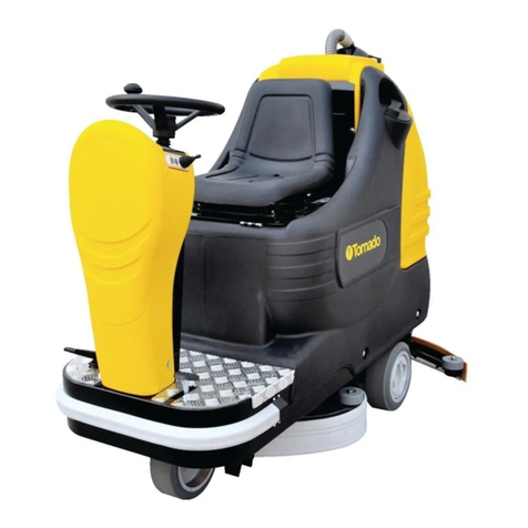
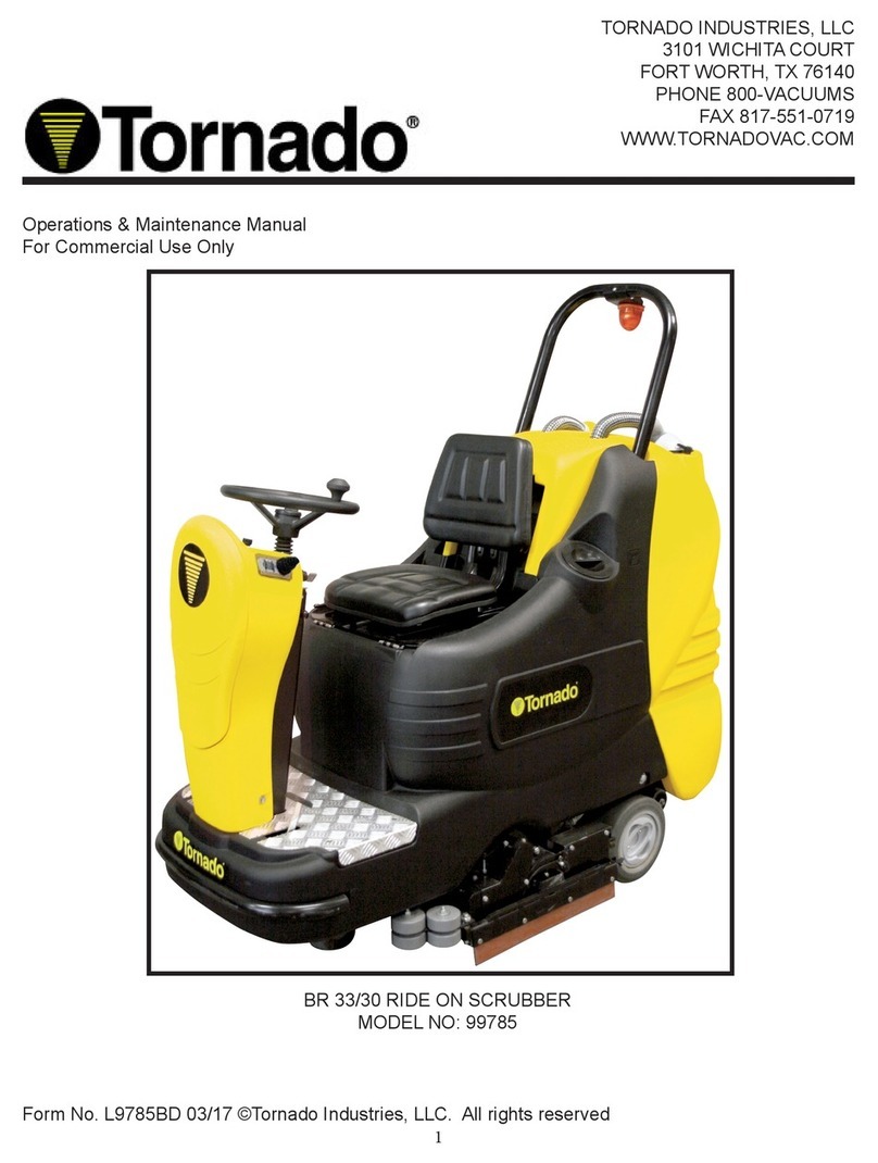
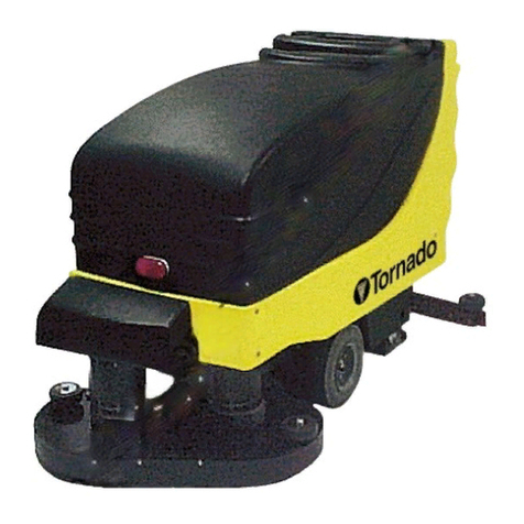
BD 26/27 RIDE ON SCRUBBER
MODEL NO: 99772
https://harrissupplyind.com-ToOrderPartsCall608-268-8080

Long Term Buyer Protection Limited Warranty
10 Years*
Plastic water tanks and Rotationally-molded bodies
2 Years*
Parts on all Tornado cleaning equipment
1 Year*
Labor on all Tornado cleaning equipment
1 Year*
Warranty on batteries, one year prorated
All battery warranties are handled directly by the battery manufacturer, on a one year prorated basis
Tornado Industries, LLC. (Tornado) warrants to the end/user customer that the Tornado product(s) will
be free from defects in material and workmanship for the duration(s) described below. This limited
warranty DOES NOT cover machines and/or components subject to normal wear and tear, damage
that occurs in shipping, failures resulting from modication, accident, unsuitable operating environ-
ment, misuse, abuse, neglect, or improper maintenance by you. For full details, contact your Autho-
rized Tornado Distributor, Service Center, or the Tornado Technical Service Department. Tornado
sales and service representatives are not authorized to waive or alter the terms of this warranty, or to
increase the obligations of Tornado under the warranty.
Terms subject to change without notice
1. Except all Windshears™ Blowers, Storm, TV2SS, Side and Downdraft, Insulation Blowers, CV 30,
CV 38, CK14/1 PRO, CK 14/2 PRO, SWM 31/9, CK LW13/1, CK LW 13/1 ROAM, CV 38/48 Dual,
PV6, PV10, PV6 ROAM, Wall Mount Vacuum and all chargers are warranted for 1 (one) year for both
parts and labor.
2. All non-wear item parts purchased after warranty expiration are warranted for 90 days.
3. Warranty starts from the date of sale to the consumer or, at Tornado’s discretion, 6 months after
the dealer purchased the unit from Tornado, whichever comes rst.
4. The EB 30 is warranted for a period of 90 days for both parts and labor.
5. The warranty on engines used on propane powered equipment is limited to motor manufacturer’s
warranty.
6. Ride-on Scrubbers are warranted for 24 months, parts, 6 months labor or 1,000 hours, whichever
occurs rst.
Note: Tornado, The Latest Dirt, Floorkeeper,
Carpetkeeper, Carpetrinser, Carpetrinser/Dryer,
Headmaster, Taskforce, PAC-VAC, T-Lite, Glazer,
Windshear, Max-Vac and Trot-Mop are trademarks
of Tornado Industries
Website: www.tornadovac.com
Phone 1-800-VACUUMS
Fax 817-551-0719
Address 3101 Wichita Court
Fort Worth, TX 76140
Form F2662.©2017. All rights reserved
1-800-VACUUMS 90 Years of Cleaning Innovation A Tacony Company
https://harrissupplyind.com-ToOrderPartsCall608-268-8080

3
NOTES
https://harrissupplyind.com-ToOrderPartsCall608-268-8080

4
GROUNDING INSTRUCTIONS
This appliance must be grounded. If it should malfunction or breakdown, grounding provides a path of least
resistance for electric current to reduce the risk electric shock. This machine is equipped with a cord having an
equipment -grounding conductor and grounding plug. The plug must be inserted into an appropriate outlet that
is properly installed and grounded in accordance with all local codes and ordinances.
WARNING: Improper connection of the equipment-grounding conductor can result in a risk of electric shock.
Check with a qualied electrician or service person if you are in doubt as to whether the outlet is properly
grounded. Do not modify the plug provided with the appliance - if it will not t the outlet, have a proper outlet
installed by a qualied electrician.
This appliance is for use on a nominal 120-volt circuit, and has a grounding plug that looks like the plug
illustrated in sketch A.
https://harrissupplyind.com-ToOrderPartsCall608-268-8080

5
SUMMARY
LEGEND PANEL OF CONTROLS 6 Working in manual mode 16
LEGEND MACHINE 7 Working adjustments 17
TECHNICAL DESCRIPTION 8 Adjustment of the detergent solution ow 17
INTRODUCTORY COMMENT 9 Adjustment of the brushes pressure 17
GENERAL RULES OF SECURITY 9 Electric protection 17
SYMBOLOGY 9 Overow device 18
OPTIONAL ACCESSORIES 10 STOP OF THE MACHINE AFTER CLEANING
OPERATION
18
BEFORE USE 10 DAILY MAINTENANCE 18
Handling of the packed machine 10 Recovery tank emptying and cleaning 18
Unpacking of the machine 10 Suction lter cleaning 18
Access to the battery compartment 10 Brushes cleaning 18
Battery installation 11 Brushes disassembly 18
Battery recharger 11 Squeegee cleaning 19
Incorporated battery recharger (optional) 11 WEEKLY MAINTENANCE 19
Batteries recharging 11 Rear squeegee rubber check 19
Batteries recharging with incorporated charger (optional) 11 Squeegee hose cleaning 19
Batteries disposal 12 Cleaning of solution tank and lter 19
Battery connections and switching on machine 12 TWO-MONTHLY MAINTENANCE 19
Batteries charge level indicator 12 Front squeegee rubber check 19
Setting of the battery check card 12 SIX-MONTHLY MAINTENANCE 19
Hour meter 13 Splash guard rubber check 19
Squeegee assembly 13 Cleaning of the inner lter solution tank 20
Adjustment of the squeegee 13 TROUBLESHOOTING GUIDE 20
Splash guard assembly 13 The suction motor does not work 20
Brushes assembly 14 The brushes motor does not work 20
FLOOR CLEANING 14 The traction motor does not work 20
Recovery tank 14 The water does not come down onto the brush-
es or is insufcient
20
Detergent solution tank 14 The machine does not clean properly 21
3SD system Solution Saving System Dispenser (optional) 14 The squeegee does not dry perfectly 21
STARTING OF THE MACHINE 15 Excessive foam production 21
Forward and backward movement 15 PROGRAMMED MAINTENANCE 21
Horn 16 RECOMMENDED BRUSHES 22
Working brake 16
Parking brake 16
Manual movement of the machine 16
Automatic squeegee lifting in reverse 16
Working in automatic mode 16
https://harrissupplyind.com-ToOrderPartsCall608-268-8080

6
LEGEND PANEL OF CONTROLS
1DISPLAY 15 SIGNAL LAMP PARKING BRAKE ON
2SIGNAL LAMP MANUAL MODE ON 16 SIGNAL LAMP UP/DOWN BRUSHES
3PUSH BUTTON FOR MANUAL MODE 17 PUSH BUTTON UP/DOWN BRUSHES
4SIGNAL LAMP MODE BREAK WASHING ON 18 SIGNAL LAMP BRUSHES ROTATION
5PUSH BUTTON FOR MODE BREAK WASHING 19 PUSH BUTTON WATER OPENING (SOLENOID
VALVE) or PUSH BUTTON ADJUSTMENT DETER-
GENT DOSAGE 3SD system (OPTIONAL)
6PUSH BUTTON FOR MODE AUTOMATIC 20 SIGNAL LAMP WATER OPEN (SOLENOID VALVE)
7SIGNAL LAMP AUTOMATIC MODE ON 21 PUSH BUTTON FOR SPEED SELECTION
8SIGNAL LAMP SUCTION MOTOR ON 22 SIGNAL LAMP SELECTION FAST SPEED
9SWITCH SUCTION MOTOR 23 SIGNAL LAMP SELECTION SLOW SPEED
10 BRUSHES PRESSURE ADJUSTMENT KNOB 24 KEY SWITCH MACHINE ON
11 PUSH BUTTON UP/DOWN SQUEEGEE 25 SWITCH FOR FRONT LIGHT (OPTIONAL)
12 SIGNAL LAMP UP/DOWN SQUEEGEE 26 PUSH BUTTON HORN
13 PUSH BUTTON VISUALIZATION HOUR METER
(DISPLAY)
27 KNOB FOR SOLUTION VALVE
14 PUSH BUTTON VISUALIZATION BRUSHES PRES-
SURE SET (DISPLAY)
28 DIRECTION OF DRIVE SELECTOR
https://harrissupplyind.com-ToOrderPartsCall608-268-8080

7
LEGEND MACHINE
1RECOVERY TANK 11 EXHAUST HOSE RECOVERY TANK
2SOLUTION TANK 12 SQUEEGEE ASSEMBLY
3 SEAT 13 CONTROL PANEL
4 DRIVE WHEEL 14 ELECTRICAL LAYOUT COVER
5 CAP FOR DETERGENT SOLUTION 15 ACCELERATOR PEDAL
6 SUCTION HOSE 16 SOLUTION DRAIN PLUG
7 SUCTION COVER 17 DETERGENT SOLUTION OUTER FILTER
8 BLOCKING LEVERS SUCTION COVER 18 TRACTION MOTOR WHEEL
9 SQUEEGEE HOSE 19 BOTTOM PLATE
10 RECOVERY TANK HOSE PLUG 20 BRUSHES BASE GROUP
21 REAR WHEELS
https://harrissupplyind.com-ToOrderPartsCall608-268-8080

8
TECHNICAL DESCRIPTION
99772 U/M
Cleaning width in/mm 26/660
Squeegee width in/mm 33/835
Working capacity, up to sq.ft./h/sqm/h 35,521/3300
Brushes diameter in/mm 2 x 14/345
Brushes rpm rpm 190
Pressure on the brushes lbs./kg 132/60 max
Brushes motor A/W 27/650
Traction motor A/W 25/600
Suction motor A/W 24/580
Suction vacuum mbar 160
Type of drive autom.
Movement speed mph/km/h 3.15,0
Maximum gradient % 10
Solution tank gallon/l 26/100
Recovery tank gsllon/l 27/105
Machine length in/mm 60/1520
Machine height in/mm 52/1320
Machine width (without squeegee) in/mm 29/730
Weight of the machine (empty and without batteries ) lbs./kg 525/238
Capacity of the batteries Ah 5 240
Weight of the batteries lbs./kg 441/200
Compartment of the batteries in/mm 16x20.5x15/415x520x385
Acoustic pressure level (in conformity with EN
60704-1)
dB (A) < 70
Vibration whole body m/sqs <0,5
Vibration to the system hand-arm m/sqs <2,5
Class III
Protection level IP 23
Tension of the batteries V 24
https://harrissupplyind.com-ToOrderPartsCall608-268-8080

9
INTRODUCTORY COMMENT
Thank you for choosing our machine. This oor
cleaning machine is used for the industrial and
commercial cleaning and is able to clean any
type of oor. During its movement, the combined
action of the brushes and the detergent solution
removes the dirt which is recovered through
the rear suction assembly, giving a perfectly
dry surface. The machine must be used only
for such purpose. It gives the best performance
if it is used correctly and maintained in perfect
efciency. We therefore ask you to read this
instruction booklet carefully whenever difculties
arise in the course of the machine’s use. In
case of need, we ask you to contact our service
department for all advice and servicing as may
prove necessary.
GENERAL RULES OF SECURITY
The rules below have to be followed carefully in
order to avoid damages to the operator and to
the machine.
- Read the labels carefully on the machine. Do
not cover them for any reason and replace them
immediately if damaged.
- The machine must be used exclusively by
authorized staff that has been instructed for its
use.
- During the working of the machine, pay at-
tention to other people and especially to the
children.
- In case of danger release the accelerator pedal
so to activate the parking brake.
- Leaving the machine in parking position, take
off the key from the instrument board.
- Do not mix different detergents, avoiding harm-
ful odors.
- Storage temperature: between -25°C and
+55°C.
- Perfect operating temperature: between 0°C
and 40°C.
- The humidity should be between 30 and 95%.
- Do not use the machine in explosive atmo-
sphere.
- Do not use the machine as a means of trans-
port.
- Do not use acid solutions in such concentra-
tions that could damage the machine and/or the
persons.
- Do not use the machine on surfaces covered
with inammable liquids or dusts (for example
hydrocarbons, ashes or soot).
- In case of re, use a powder re-extinguisher.
Do not use water.
- Do not strike shelvings or scaffoldings, where
there is danger of falling objects.
- Adapt the working speed to the oor condi-
tions: particularly, slow down before narrow
curves have to be faced.
- Do not use the machine on areas having a
higher gradient than the one stated on the
number plate.
- The machine has to carry out simultaneously
the operations of washing and drying. Differ-
ent operations must be carried out in restricted
areas prohibited to non-authorized personnel.
Signal the areas of moist oors with suitable
signs.
- If the machine does not work properly, check
by conducting simple maintenance procedures.
Otherwise, ask for technical advice an autho-
rized assistance centre.
- Where parts are required, ask for ORIGINAL
spare parts to an authorized dealer.
- Use only ORIGINAL brushes indicated in the
paragraph “RECOMMENDED BRUSHES".
- For any cleaning and/or maintenance
operation take off the power supply from the
machine.
- Do not take off the protections which require
the use of tools to be removed.
- Do not wash the machine with direct water
jets or with high water pressure nor with cor-
rosive material.
- Every 200 working hours have a machine
check through an authorized service depart-
ment.
- In order to avoid scales on the solution tank
lter, do not ll the detergent solution many
hours before the machines’ use.
- Before using the machine, check that all
panels and coverings are in their position as in-
dicated in this use and maintenance catalogue.
- Restore all electrical connections after any
maintenance operation.
- Provide for the scrapping of the material of
normal wear following strictly the respective
rules.
- When, your machine has to stop activity,
provide for the appropriate waste disposal
of its materials, especially oils, batteries and
electronic components, and considering that
the machine itself has, where possible, been
constructed using recyclable materials.
SYMBOLOGY
Symbol denoting the switch for the
water opening and the signal lamp
that the water is open.
Symbol denoting the functioning
of the solution valve adjusting the
ow of the detergent solution.
Indication of the maximum tempera-
ture of the detergent solution. It is
placed near the lling hole of the
solution tank.
Symbol denoting the push button and
the signal lamp of the manual mode.
Symbol denoting the push
button and the signal lamp of the
Automatic mode.
Symbol denoting the push
button and the signal lamp of the
break wash mode.
Symbol denoting the signal lamp of
the starting of the brushes rotation.
Symbol denoting the push button to
visualize on the display the brushes
pressure set.
Symbol denoting the functioning of
the adjustment knob of the brushes
pressure.
Symbol denoting the push button
and the signal lamp up/down of the
squeegee.
Symbol denoting the switch and the
signal lamp of the suction motor.
Symbol denoting the charge level of
the batteries.
Symbol denoting the push button
to visualize the hour meter on the
display.
Symbol denoting the push button and
the signal lamps for the speed selec-
tion.
Symbol denoting the drive selector
forwards/backwards.
Symbol denoting the signal lamp of
the parking brake on.
Symbol denoting the open book.
Indicates that the operator has to
read the manual before the use of the
machine.
Warning symbol.
Read carefully the sections marked
with this symbol, for the security of
both the operator and the machine.
https://harrissupplyind.com-ToOrderPartsCall608-268-8080

10
OPTIONAL ACCESSORIES
Front light (1) and relative switch (2).
3SD System – Solution saving system
dispenser.
Incorporated battery charger.
Blinking light.
BEFORE USE
HANDLING OF THE PACKED MA-
CHINE
The machine is supplied with suit-
able packing foreseen for fork lift truck
handling.
The total weight is 591 lbs./268kg.
Packing dimensions:
Base: 70” x 37”/178 cm x 93 cm
Height: 55”/138 cm
ATTENTION:
Do not place more than 2 machines on
top of each other.
UNPACKING OF THE MACHINE
1. Remove the external packing.
2. Unscrew the brackets (1+2) that
secure the machine to the pallet.
3. Before moving the machine from
the pallet, it is necessary to unblock
the parking brake that blocks the
traction motor wheel. To do this, keep
the lever (3) lifted. With the delivery
of the machine we also supply a cord
that permits the lever operation (3).
After having moved the machine, take
off the cord and keep it for eventual
re-use.
ATTENTION:
When the parking brake is released
manually, for example when the ma-
chine has to be moved without batter-
ies, avoid covering slopes and do not
park on them either.
4. Move the machine backwards, as
indicated in the gure, avoiding heavy
contacts to mechanical parts.
5. Keep the pallet and the brackets for
eventual transport.
ACCESS TO THE BATTERY COM-
PARTMENT
1. Bring the machine on a level sur-
face.
2. Rotate the seat platform forward
and hook the bar.
When the operation is nished close
the battery compartment and reposi-
tion the seat platform.
To install a battery into the compart-
ment it is necessary to :
1. Rotate the seat platform forward
and hook the bar (2) into position A.
2. Remove the holder (1) by un-
screwing the two wing nuts under the
platform.
3. Pull the releasing lever of the seat
outwards (3) sliding the seat (4) up to
the highest position.
4. Rotate the platform further in order
to hook the bar (2) into position B.
This position allows batteries to be
handled using suitable lifting equip-
ment.
https://harrissupplyind.com-ToOrderPartsCall608-268-8080
11
In this way it will be possible to handle
the batteries with suitable lifting equip-
ment.
BATTERY INSTALLATION
The machine is equipped either with
batteries in serial connection or ele-
ments of DIN-type assembled together
and connected in series for a total of
24 Volt, placed in its appropriate com-
partment under the seat platform and
must be handled using suitable lifting
equipment (due to weight, consider-
ing the type of batteries chosen, and
coupling system).
The batteries must be in accordance
with CEI 21-5 Norms.
ATTENTION:
The machine and its battery check
card foresee the use of traditional lead
batteries.
CHECK THE SETTING OF THE
CHECK CARD (see under paragraph
"BATTERIES CHARGE LEVEL INDI-
CATOR").
In case of GEL batteries installation, it
is necessary to MODIFY THE SET-
TING of the electronic check card (see
under paragraph SETTING OF THE
BATTERY CHECK CARD”).
ATTENTION:
Strictly follow manufacturer/distributor
indications for the maintenance and
recharge of the batteries. All installa-
tion and maintenance operations must
be executed by specialized staff, using
suitable protection accessories.
For batteries installation it is necessary
to reach the battery compartment as
indicated under paragraph “ACCESS
TO THE BATTERY COMPARTMENT”.
1. Place the batteries in its compart-
ment.
2. Connect the terminals, respecting
the polarities, avoiding contact with
other parts that could create short
circuit.
BATTERY RECHARGER
Make sure that the battery recharger is
suitable for the installed batteries both
for their capacities and type (lead/acid
or GEL and equivalent).
BATTERY RECHARGER
Make sure that the battery recharger is
suitable for the installed batteries both
for their capacities and type (lead/acid
or GEL and equivalent).
In the plastic bag containing the use
and maintenance you will nd the
coupling connector for the recharger. It
must be assembled onto the cables of
your recharger, following the instruc-
tions given by the manufacturer.
ATTENTION:
This operation must be carried out by
qualied staff. A wrong or faulty cable
connection can cause serious dam-
ages to persons or things.
INCORPORATED BATTERY RE-
CHARGER (OPTIONAL)
If the machine is equipped with the
incorporated battery recharger (see
under "OPTIONAL ACCESSORIES”)
please refer to the instructions of this
accessory.
The battery recharger is connected
directly to the battery poles.
During the recharging operations a
device is activated which disables the
machine.
The mains cable of the battery re-
charger has a maximum length of two
metres and must be connected to a
single-phase socket type CEE 7/7.
BATTERIES RECHARGING
1. Plug the connector (2) of the bat-
tery recharger into the battery connec-
tor (1).
2. Proceed for the recharging.
BATTERIES RECHARGING WITH
INCORPORATED CHARGER (OP-
TIONAL)
Bring the machine on a level surface
near to a single-phase 120V 60 Hz
socket, nominal current 10A.
Switch off the switches of the brushes
motor, the suction motor and the sole-
noid valve.
1. Insert the plug into the mains
socket.
2. Proceed to recharge, keeping the
seat base lifted (see under paragraph
“ACCESS TO THE BATTERY COM-
PARTMENT” in “BEFORE USE”).
3. At the end of the recharging, take
off the plug from the mains socket.
ATTENTION:
Never charge a GEL battery with a
non suitable recharger. Strictly follow
the instructions supplied by the batter-
ies and recharger manufacturer.
In order not to cause permanent dam-
ages to the batteries, it is necessary
to avoid their complete discharge,
providing for the recharging within a
few minutes after that the batteries
discharge signal starts blinking.
https://harrissupplyind.com-ToOrderPartsCall608-268-8080
12
NOTE: Never leave the batteries
completely discharged even if the ma-
chine is not used. In case of traditional
batteries, please check the electrolyte
level every 20 recharging cycles and
eventually top them up with distilled
water. Never leave the batteries dis-
charged for more than two weeks.
ATTENTION:
For the recharge of the batteries it is
necessary to strictly follow all the indi-
cations given by the manufacturer/dis-
tributor. All the installation and main-
tenance operations must be carried
out by qualied staff. Danger of gas
exhalations and emission of corrosive
liquids. Fire danger: do not approach
with free ames.
BATTERIES DISPOSAL
It is compulsory to hand over exhaust-
ed batteries, classied as dangerous
waste, to an authorized institution ac-
cording to the current laws.
CONNECTION BATTERIES' CON-
NECTOR AND SWITCHING ON OF
THE MACHINE
Once that the battery recharging has
been completed:
1. Disconnect the connector of the
battery recharger from the battery con-
nector (1).
2. Connect instead the machine con-
nector (2).
BATTERIES CHARGE LEVEL INDI-
CATOR
To start any function of the machine,
it is necessary to rotate clockwise the
key switch (A). Rotating it counter-
clockwise any function will be switched
off.
WHEN THE MACHINE IS SWITCHED
ON, ON THE DISPLAY (1) APPEAR
IN ORDER THE FOLLOWING INFOR-
MATION:
1. The machine model (for example
AdL).
2. The setting of the battery check
card which can be: GE 24 (check
card set for GEL batteries). or
Pb 24 (check card set for lead batter-
ies).
3. The version of the software pro-
gramme of the card (for example 4-6).
4. The batteries charge level indica-
tor is digital and remains xed on the
display. The battery charge level starts
from -100-, which indicates the 100%
of the total charge and decreases
from 10 to 10. When the charge
level reaches -20-, the display starts
blinking, so you are about the end of
working.
ATTENTION:
When the indication -10- appears
blinking, automatically the brushes
stop, while the suction continues to
work. When there are four lines blink-
ing, the suction will also stop auto-
matically. The traction system remains
functioning to enable movement to
transfer the machine to the place
provided for the tank emptying and for
the recharge of the batteries.
SETTING OF THE BATTERY CHECK
CARD
The setting of the battery check card
can be:
GE 24 (check card set for GEL batter-
ies).
or
Pb 24 (check card set for lead batter-
ies).
The machine is supplied with the bat-
tery check card set for the installed
batteries. To modify this setting, it is
necessary to:
1. Switch the machine off and then
back on.
2. Immediately after having switched
on, when on the display (1) the writ-
ing Pb24 appears, press and hold
the push buttons (2) and (3) until the
display starts to blink.
3. When the display starts to blink, re-
lease the push buttons (2) and (3) and
press once the push button (3).
https://harrissupplyind.com-ToOrderPartsCall608-268-8080
13
4. The display ‘GE24’ starts to blink.
5. When the display stops blinking, the
setting is modied.
To change from GEL to Lead-Acid,
repeat the procedure pressing button
(2) instead of button (3).
ATTENTION:
As the machine is a 24V model, do not
set the batteries at 36V.
HOUR METER
The machine is equipped with an hour
meter located on the same display (1)
of the battery charge level indicator.
Keeping the button (2) pressed, the
rst data indicates the working hours
and after a few seconds the working
minutes are shown.
SQUEEGEE ASSEMBLY
1. Hold the squeegee support (1) lifted
from the oor.
2. Insert the threaded parts of the two
knobs (4) making them slide inside
the two slots on the support placed on
the upper part of the squeegee (2).
3. Put the washers (3) into position,
there are two for each knob, so that
they are assembled one under and
the other on top of the two slots on the
support.
4. Secure the squeegee by rotating
the two knobs (4) clockwise.
5. Insert the squeegee hose (5) into
its coupling, as indicated in the gure.
ADJUSTMENT OF THE SQUEEGEE
In order to have a perfect drying
result through the squeegee, the rear
rubber must have the lower bending
uniformly adjusted in all its length. For
the adjustment, it is necessary to put
the machine in working condition and
the vacuum motor has to be switched
on and the brushes have to function
together with the detergent solution.
The lower part of the rubber is too
much bent
Take off the pressure rotating the wing
nut (6) counterclockwise.
The lower part of the rubber is not
much bent
Increase the pressure rotating the
wing nut (6) clockwise. Check that
the wheels which adjust the height
do not rest on the oor, in this case
adjust them as indicated in paragraph
"Height adjustment".
The bending is not uniform
Adjust the squeegee inclination rotat-
ing counterclockwise the wing nut (7)
to increase the bending in the central
part, or clockwise to increase the
bending on the extremities.
Height adjustment
Once that the pressure and inclination
of the squeegee have been adjusted,
it is necessary to x this optimum con-
dition making touch slightly the wheels
onto the oor. Rotate the registers
(8): clockwise to lower the wheels or
counterclockwise to raise them. Both
wheels must be adjusted in the same
measure.
ATTENTION:
Every type of oor requires a specic
adjustment. For example, concrete
oors (where the friction results to
be high) need little pressure, while
smooth oors (ceramics) need higher
pressure.
If the cleaning operations are made
always on the same type of oor, the
adjustment can change only in func-
tion of the rubber wear.
SPLASH GUARD ASSEMBLY
The two splash guards have to be as-
sembled onto the brushes base group
as indicated in the following gures.
Insert the metal strips inside the
suitable slots present on the rubber.
Place the round hole at the extrem-
ity of the strip onto the pin (1) placed
in the front part of the brushes base
group. Secure the strips through the
nut blocking it.
Block the coupling lever (2) in the
rear part of the brushes base group
to the ring placed at the extremity of
the metal strip still free. Please act as
above for both splash guard rubbers.
With the brushes assembled, the
splash guard must slightly touch the
oor.
For the disassembly it is necessary
to proceed inversely with above-men-
tioned operations.
https://harrissupplyind.com-ToOrderPartsCall608-268-8080

14
BRUSHES ASSEMBLY
To assemble the brushes it is neces-
sary that the brushes base is in the
lifted position. If it is not lifted, proceed
as follows:
Without the operator seated, turning
the key switch clockwise, the display
comes on and after 3 seconds all
working groups come off automatically
and are lifted from the oor.
Switch off the machine turning the key
counterclockwise.
ATTENTION:
To carry out brushes assembly opera-
tions with the electric supply on, may
cause damages to hands.
With the brushes base group in lifted
position, insert the brushes into their
plate seat underneath the brushes
base turning them until the three metal
buttons are properly seated in their
slots; quickly rotate the brushes to
push the button towards the coupling
spring until they get blocked. The
gure shows the rotating direction for
brushes coupling.
For a longer life of the brushes we
suggest to invert daily their posi-
tion. Whenever brushes become
de¬formed we suggest to reassemble
them in the same position, in order
to avoid the different inclination of
the bristles to cause excessive motor
overload or troublesome vibrations.
ATTENTION:
Use only brushes supplied with the
machine or the ones indicated in
the paragraph “RECOMMENDED
BRUSHES”. The use of other brushes
can compromise the result.
FLOOR CLEANING
RECOVERY TANK
Check that the cover of the suction
lter (1) is correctly secured, after
rotating the levers (2) and that the
suction motor hose (3) is correctly
connected to it.
Verify also that the squeegee hose
couplings (4/5) are correctly inserted
into their seats and that the exhaust
hose plug (6) placed in the rear part of
the machine is well closed.
DETERGENT SOLUTION TANK
The capacity of the detergent solution
tank is indicated in the technical data.
Open the screw plug placed in the left
part of the machine and ll the deter-
gent solution tank with clean water
at a maximum temperature of 122°F
(50°C). Add the liquid detergent in the
percentage and conditions recom-
mended by the manufacturer. To avoid
excessive foam, which could cause
problems to the vacuum motor, use
the minimum percentage of detergent.
Screw down the plug to close the tank.
ATTENTION:
Always use low foam detergent. To
avoid foaming, before starting opera-
tions, introduce into the recovery tank
a minimum quantity of anti-foam prod-
uct. Never use pure acid.
3SD SYSTEM SOLUTION SAVING
SYSTEM DISPENSER (OPTIONAL)
The system permits the predetermined
dosing of the detergent percentage
which will be mixed with the water of
the solution tank. The detergent is
contained in a transparent tank with a
capacity of 8 liters, placed in the front
part of the machine.
With the brushes moving, pressing
the push button (A) on the instrument
board, on the display (1) the indication
shows the detergent percentage which
is being used.
https://harrissupplyind.com-ToOrderPartsCall608-268-8080

15
Pressing the same push button in
succession, six different possibilities of
setting can be selected and the display
(1) visualizes always the percentage.
The indication of the level corresponds
to the following detergent percentages
in the water:
d 0.0
d 0.3
d 0.6
d 1.2
d 2.4
d 4.5
The dosing adjustment set remains
stored by the system even with the
machine stopped. The water ow is
adjusted through the 8-way commuta-
tor (B): one OFF position and 7 oper-
ating positions from a minimum of 1,2
liters/min to a maximum of 3,7 liters/
min. In OFF position both the water
ow and its relative detergent ow is
interrupted.
When the commutator (B) is in OFF
position, an auxiliary water system can
be activated, that permits the tradi-
tional use of the machine and there-
fore the lling of the solution tank with
water and detergent without using the
system and therefore without the use
of the pumps. In this case it is neces-
sary to open and adjust manually a
solution valve (C) placed under the
machine. In this situation the push but-
ton (A) handles the command of the
solenoid valve in manual function.
NOTE: when restarting the work in
mode 3SD, it is important that the
solution valve (C) is closed, this is to
maintain the predetermined propor-
tions water-detergent.
NOTE: if the automatic dosing system
is not being used for a long time, it is
possible that the hoses of the deter-
gent circuit are emptied and therefore
at the rst use, the detergent begins
to come out onto the brushes with a
certain delay compared to the water
outlet. Through the solution valve (D)
it is possible to empty the detergent
tank and to recover the detergent.
STARTING THE MACHINE
A safety device avoids the machine’s
movement if the operator is not seated
correctly on the guiding place.
To switch on the machine:
1. Sit on the seat.
2. Turn the key switch (1) clockwise to
switch on the machine. Automatically,
the machine gets ready in manual
(MAN) mode and in forward movement
with the fast speed (signal lamp 2).
3. Check the charge level of the bat-
teries on the display (3).
4. Pressing the push button (7) the
functioning of BREAK WASHING is
chosen and the transfer operations
of the machine are carried out (see
under paragraph “FORWARD AND
BACKWARD MOVEMENT"). When
the signal lamp (6) is on, then the ma-
chine is in BREAK WASHING mode.
5. Pressing the push button (8) the au-
tomatic (AUTO) functioning is chosen,
while pressing the push button (5), the
functioning of the machine becomes
manual (MAN).
A. When the signal lamp (9) is on, the
machine is functioning in automatic
(AUTO) mode and the machine acti-
vates and deactivates all the working
functions in an automatic mode (see
under paragraph “WORKING IN AU-
TOMATIC MODE”).
B. When the signal lamp (4) is on,
the machine is functioning in manual
(MAN) mode and it is possible to
choose if:
I. To carry out the only transfer of the
machine without activating or deacti-
vating the working functions.
II. To activate separately only the con-
trols relative to the washing function
with the brushes (see under paragraph
“WORKING IN MANUAL MODE”).
III. To activate separately only the con-
trols relative to the drying function with
the squeegee (see under paragraph
“WORKING IN MANUAL MODE”).
ATTENTION:
In manual mode every function of the
machine has to be activated or deacti-
vated manually.
FORWARD AND BACKWARD
MOVEMENT
It is recommended to always carry out
the mere transfer of the machine in
mode (BREAK WASHING).
To proceed to activate the movement
of the machine:
1. Sit on the seat.
2. Turn the key switch (1) clockwise to
switch on the machine.
3. Check the charge level of the bat-
teries on the display (5).
4. Pressing the push button (7) the
functioning of BREAK WASHING is
chosen to carry out the mere transfer
of the machine. In fact, in this mode
the washing functions of the machine
are not working and only the traction
system functions. When the signal
lamp (6) is on, then the machine is in
BREAK WASHING mode.
5. Positioning the selector (8) forward,
the forward drive is chosen, while
positioning it back, the reverse drive is
chosen.
6. Press the accelerator pedal placed
on the right part of the platform to start
the machine.
7. Adjust the movement speed in
forward pressing by push button (2) to
choose the slow one (at the maximum
1.9 mph (3,6 km/h) is reached) or the
fast one (at the maximum 3.1 mph (5
km/h) is reached). The signal lamp (3)
indicates that the fast drive is selected,
while signal lamp (4) indicates that the
slow drive is selected.
https://harrissupplyind.com-ToOrderPartsCall608-268-8080
16
8. In backward movement, when the
machine is moving, an intermittent
warning device is activated.
HORN
The machine is equipped with a horn
which is activated pressing the push
button (1).
WORKING BRAKE
To stop the machine during normal
working situations, it is sufcient to re-
lease the accelerator pedal, because
the machine has an electronic brake
system. To restart, press again the ac-
celerator pedal.
PARKING BRAKE
The machine is equipped with a park-
ing brake on the traction motor wheel
that operates at the complete release
of the accelerator pedal or when the
machine is without batteries. In case
of an emergency or simply to stop the
machine, it is sufcient to release the
accelerator pedal. The brake remains
on until the accelerator pedal is
pressed again. When the batteries are
connected and when the key switch
(A) is positioned on 1, with the brake
inserted, the lamp (2) comes on.
MANUAL MOVEMENT OF THE MA-
CHINE
To move the machine manually, it
is necessary to unblock the parking
brake that blocks the traction motor
wheel. To do this, keep the lever (3)
lifted. With the delivery of the machine
we also supply a cord that permits
the lever operation (3). After having
moved the machine, take off the cord
and keep it for eventual re-use.
ATTENTION:
When the parking brake is released
manually, for example when the ma-
chine has to be moved without batter-
ies, avoid slopes and do not park on
them either.
AUTOMATIC SQUEEGEE LIFTING
WHEN GOING BACKWARDS
When the backwards movement is
selected the squeegee is brought
automatically to the upper position. It
will then lower again in the following
forward movement. This happens
both in automatic and in manual mode
in order to protect the integrity of the
squeegee.
WORKING IN AUTOMATIC MODE
The automatic operation is useful to
simplify the operator’s work.
1. Activate the machine (see under
paragraph “STARTING OF THE MA-
CHINE”).
2. Pressing the push button (3) the au-
tomatic (AUTO) functioning is chosen.
When the signal lamp (4) is on, then
the machine is functioning in automat-
ic (AUTO) mode.
3. Check that the knob of the solution
valve (5) is in the position of optimum
ow, depending on the type of oor
and the type of dirt (see under the
paragraph “FLOW ADJUSTMENT OF
THE DETERGENT SOLUTION”).
4. Position the selector (1) forward to
choose the forward drive.
5. Adjust the movement speed in
forward with the push button (2) (see
under paragraph "FORWARD AND
BACKWARD MOVEMENT").
6. Pressing the accelerator pedal,
the machine begins to move and in
automatic mode all the working func-
tions are activated. Automatically both
the brushes base and the squeegee
go down, the brushes begin to turn,
the solenoid valve opens to permit the
detergent solution to ow down onto
the brushes and the suction system
is activated to recover the dirty water
from the oor.
Move the selector backwards (1) to
choose the reverse drive and pressing
the accelerator pedal the reverse drive
starts, the squeegee lifts automati-
cally and will then lower itself during
the next forward movement. If the
accelerator pedal is released for more
than 3 seconds, automatically all the
functions are switched off and both the
brushes base and the squeegee are
lifted. Pressing the pedal again, the
machine starts to move again and in
automatic mode all the working func-
tions are reactivated.
WORKING IN MANUAL MODE
The manual mode is useful when, in
special cases, it is necessary to carry
out separately only the washing with
the brushes or only the drying of the
oor.
ATTENTION:
The washing and drying functions,
when they are not carried out simul-
taneously, represent an improper use
of the machine (see under paragraph
“GENERAL RULES OF SECURITY”).
If they are carried out separately, it is
necessary to forbid the working areas
to the passage of non-authorized
personnel and to signal the areas of
moist oors with suitable signs.
1. Activate the machine (see under
paragraph “STARTING OF THE MA-
CHINE”).
https://harrissupplyind.com-ToOrderPartsCall608-268-8080
17
2. Pressing the push button (2) the
functioning of manual (MAN) mode is
chosen. When the signal lamp (1) is
on, then the machine is functioning in
manual (MAN) mode.
TO CARRY OUT THE WASHING
WITH ONLY THE BRUSHES:
1. Check that the knob of the solution
valve (8) is in the position of optimum
ow, depending on the type of oor
and the type of dirt (see under the
paragraph “FLOW ADJUSTMENT OF
THE DETERGENT SOLUTION”).
2. Press the push button (6) of up/
down of the brushes base to lower
the brushes. Once it is lowered, the
brushes begin to turn. The blinking sig-
nal lamp (7) indicates that the brushes
base is lowering or lifting (it remains
on when the brushes base is in work-
ing position), while the signal lamp (5)
signals that the brushes are turning.
3. Press the switch (4) to open the so-
lenoid valve and permit the detergent
solution to lower onto the brushes. The
signal lamp (3) will come on, to indi-
cate that the solenoid valve is open.
TO CARRY OUT THE FUNCTION OF
ONLY DRYING:
1. Press the push button (14) of up/
down squeegee to lower the squee-
gee. The blinking signal lamp (13)
indicates that the squeegee is lower-
ing or lifting (it remains on when the
squeegee is in working position).
2. Press the switch (12) of the suc-
tion motor to start the suction system.
The signal lamp (11 indicates that the
machine is drying.
Position the selector (9) forward to
choose the forward drive. Adjust the
movement speed in forward with the
push button (10) (see under para-
graph "FORWARD AND BACKWARD
MOVEMENT”).
Pressing the accelerator pedal, the
machine begins to move forward and
to work according to the set functions.
ATTENTION:
In manual mode every function of the
machine has to be activated or deacti-
vated manually.
WORKING ADJUSTMENTS
Both in automatic and in manual
mode, during the rst feet (metres)
check:
1. that the squeegee adjustment guar-
antees a perfect drying result (see
under paragraph “ADJUSTMENT OF
THE SQUEEGEE”).
2. that the adjustment of the detergent
solution ow is sufcient to wet the
oor uniformly avoiding the leakage of
detergent from the splash guards (see
under paragraph “FLOW ADJUST-
MENT OF THE DETERGENT SOLU-
TION”).
3. that the brushes pressure permits
an efcient washing action in function
of the dirt and the speed (see under
paragraph “ADJUSTMENT OF THE
BRUSHES PRES-SURE”).
FLOW ADJUSTMENT OF THE DE-
TERGENT SOLUTION
To adjust the detergent solution quan-
tity that ows down onto the brushes
it is necessary to rotate the solution
valve knob (1) placed on the right of
the steering column, rotating counter-
clockwise to increase it and clockwise
to reduce it up to close the ow.
It is better to adjust the water ow dur-
ing work and at every adjustment of
the brushes pressure.
ADJUSTMENT OF THE BRUSHES
PRESSURE
Through the knob (4) it is possible to
adjust the brushes pressure onto the
oor in three pre-set pressure levels.
We can visualize on the display (1) the
pressure in kg previously set by press-
ing the push button (3).
The adjustment occurs in this way
both in automatic and in manual mode.
ATTENTION:
In order not to overload the brushes
motor, it is convenient to reduce the
brushes pressure going from smooth
oors to rough ones (ex. concrete).
The visualization of the blinking led (2)
indicates an overload of the brushes
motor. It is therefore necessary to
reduce the pressure up to the level
where the blinking warning stops.
ELECTRIC PROTECTION
The machine is equipped with an
electronic system of protection for all
components that carry out functions of
power or control. This device blocks
the defective component and indicates
on the display (1) the corresponding
alarm from ”A1”, “A2” and on.
ATTENTION:
To restore the functioning of the
component, turn off and on again the
machine acting upon the key switch.
If the problem persists, please contact
the authorized technical assistance.
https://harrissupplyind.com-ToOrderPartsCall608-268-8080
18
OVERFLOW DEVICE
In order to avoid serious damages
to the suction motor, the machine is
equipped with a mechanical oat that
intervenes when the recovery tank is
full, closing the air ow of the suction.
When this happens, it is necessary to
empty the recovery tank (see under
paragraph “RECOVERY TANK EMP-
TYING AND CLEANING”).
STOP OF THE MACHINE AFTER
CLEANING OPERATION
IN AUTOMATIC OR MANUAL
WORKING MODE:
1. A the end of the washing cycle,
pressing the push button (1), the func-
tioning of BREAK WASHING is cho-
sen. When the signal lamp (2) is on,
then the machine then the machine
is in BREAK WASHING mode. In this
way automatically the brushes lift, the
solenoid valve shuts down and it is
possible to nish the drying operation
for a total time of about 15 seconds,
afterwards also the squeegee is lifted
and the suction stops.
NOTE: all these phases are carried
out with the machine operating, so
that the squeegee can dry the clean-
ing area from the “drying phase of the
brushes” and furthermore can dry the
suction hose of its dirty water.
At any time it is possible to interrupt
the procedure BREAK WASHING by
stopping the drive.
2. During the phase of BREAK WASH-
ING, when the accelerator pedal is
released for more than 3 seconds, the
squeegee raises itself and the suction
switches off automatically.
3. After three seconds, the accelerator
can be pressed again, if a machine's
transfer has to be made (you can
make the transfer even if the pedal is
not lifted once the 15 seconds have
passed).
4. Turn the switch key counterclock-
wise to switch off the machine.
ATTENTION:
The mode (BREAK WASHING) is
specic for the transfer at the end of
the cleaning operation.
Re-start the cleaning operation:
A. by pressing the push button (4)
the automatic (AUTO) functioning is
chosen to start working in automatic
mode.
B. by pressing the push button (3) the
manual (MAN) functioning is chosen
to start working in manual mode and
all functions have to be re-established
manually.
DAILY MAINTENANCE
ATTENTION:
All the following maintenance and
cleaning operations that refer to the
following components that are in con-
tact with liquids and therefore:
• Solution and recovery tanks
• Solution and recovery lters
• Squeegee with their rubbers and
hoses
• Brushes
must be carried out using gloves to
protect from contact with dangerous
solutions.
RECOVERY TANK EMPTYING AND
CLEANING
1. Remove the exhaust hose (1) from
the holding bracket.
2. Remove the plug (2) from the
exhaust hose by pulling on the lever
(3) and empty the recovery tank into
appropriate containers, in compliance
with the respective rules.
3. Take off suction cover (4) after rotat-
ing the blocking levers (5).
4. Take off the lter and lter protection
(6).
5. Rinse the inside of the tank with a
water jet.
6. Reassemble all parts.
SUCTION FILTER CLEANING
1. Take off suction cover (4) after rotat-
ing the blocking levers (5).
2. Take off the lter (8) and the lter
protection (6).
3. Clean all parts with a water jet,
especially the inside surfaces and the
lter bottom.
4. Reassemble all parts.
BRUSHES CLEANING
Disassemble the brushes and clean
them with a water jet (for the brushes
disassembly see under paragraph
“BRUSHES DISASSEMBLY”).
https://harrissupplyind.com-ToOrderPartsCall608-268-8080
19
BRUSHES DISASSEMBLY
With the brushes base in lifted position
(see under paragraph "BRUSHES AS-
SEMBLY"), rotate the brushes sharply
in order to release the button from the
coupling spring until it becomes free
and wash them with a water jet. The
gure shows the rotating sense for
brushes release.
ATTENTION:
To carry out brushes disassembly
operations with the electric supply on,
may cause damages to hands.
SQUEEGEE CLEANING
Keeping the squeegee clean guaran-
tees the best drying result.
For cleaning it is necessary to:
1. Take off the squeegee hose (5) from
the coupling.
2. Disassemble the squeegee (2) from
its support (1) by loosening the knobs
(4) counterclockwise.
3. Clean the internal part of the squee-
gee inlet.
4. Clean the squeegee rubbers.
5. Reassemble all parts paying atten-
tion to put the washers (3) into posi-
tion, they are two for each knob, so
that they are assembled one under
and the other on top on each of the
two slots on the support.
WEEKLY MAINTENANCE
REAR SQUEEGEE RUBBER CHECK
Check the squeegee rubber wear and
turn or replace it if needed.
For the replacement it is necessary to:
1. Lift the squeegee (see under
paragraph “STOP OF THE MACHINE
AFTER CLEANING OPERATION”). 2.
Unhook the latches (1).
3. Unscrew the wing nuts (2) to take
off the terminals of the outer rubber
holder blades (3) and then take off the
central rubber holder blade (4).
4. Take off the rubber (5), turn it to a
new side or replace it.
To reassemble the squeegee reverse
the operations.
SQUEEGEE HOSE CLEANING
Weekly or in case of insufcient suc-
tion, it is necessary to check that the
squeegee hose is not obstructed. To
clean it, proceed as follows:
1. Take off the hose (1) from the
squeegee coupling.
2. Wash the inside of the hose with a
water jet.
3. To reassemble the hose reverse the
operations.
CLEANING OF THE SOLUTION
TANK AND OF THE OUTER FILTER
1. Bring the machine to an appropri-
ate place for the detergent solution
draining.
2. Unscrew the solution tank cap (1).
3. Unscrew the lter cap (2) and take
off the lter. Be careful not to lose the
gasket of the cap.
4. Unscrew the drain plug of the deter-
gent solution (3).
5. Rinse the solution tank and the
components of the lter with a water
jet.
6. Reassemble all parts.
TWO-MONTH MAINTENANCE
FRONT SQUEEGEE RUBBER
CHECK
Check the wear of the squeegee rub-
ber and eventually replace it.
For the replacement it is necessary to:
1. Take off the squeegee (see under
paragraph “SQUEEGEE CLEANING”).
2. Disassemble the rear part of the
squeegee (see under paragraph
“REAR SQUEEGEE RUBBER
CHECK”).
3. Unscrew the wing nuts (1) and take
off the front rubber holder blade (2).
4. Replace the front rubber (3).
To reassemble the squeegee reverse
the operations.
SIX-MONTH MAINTENANCE
SPLASH GUARD RUBBER CHECK
With the brushes assembled, the
splash guards must slightly touch the
oor. If they are worn, they have to
be replaced. Just release the springs
placed in the rear part of the brushes
base group from the slots placed at
the free ends of the metal strips to
remove the rubbers and to reinsert
the new ones (see under paragraph
“SPLASH GUARD ASSEMBLY”).
https://harrissupplyind.com-ToOrderPartsCall608-268-8080

20
CLEANING OF THE INNER FILTER
SOLUTION TANK
Empty the solution tank, remove the
tting (1) of the water outlet by taking
off the two screws that x it to the tank
in the rear part of the machine. Clean
the inside lter part of the tting. Pour
some water into the tank to clean it.
Reassemble the tting onto the solu-
tion tank.
TROUBLESHOOTING GUIDE
ATTENTION:
If, with the key switch positioned
clockwise to switch on the machine
the display and other functions are
not activated, it is necessary to check
the batteries’ connection to the ma-
chine (see under paragraph “CON-
NECTION BATTERIES’ CONNEC-
TION AND SWITCHING ON OF THE
MACHINE”). If the problem persists,
please contact the authorized techni-
cal assistance.
THE SUCTION MOTOR DOES NOT
WORK
1. Verify that the key switch (1) is
positioned clockwise to switch on the
machine. If alarm signals are dis-
played, it is necessary to switch off
and on again the machine to restore
the functionality.
2. Check the charge level of the bat-
teries on the display (2).
3. Verify having correctly activated
the function of drying (see under
paragraph “STARTING OF THE MA-
CHINE”).
4. Check that the recovery tank is not
full.
5. If, both in mode (MAN) and
(AUTO), the signal lamp (3) is on but
the suction system does not work,
please contact the authorized techni-
cal assistance.
THE BRUSHES MOTOR DOES NOT
WORK
1. Verify that the key switch (1) is
positioned clockwise to switch on the
machine. If alarm signals are dis-
played, it is necessary to switch off
and on again the machine to restore
the functionality.
2. Check the charge level of the bat-
teries on the display (2).
3. Verify of having correctly activated
the function of washing with the brush-
es (see under paragraph “STARTING
OF THE MACHINE”).
4. If, both in mode (MAN) and (AUTO),
the signal lamp (3) is on but the
brushes do not turn, please contact
the authorized technical assistance.
THE TRACTION MOTOR DOES NOT
WORK
1. Sit on the seat.
2. Verify that the key switch (1) is
positioned clockwise to switch on the
machine. If alarm signals are dis-
played, it is necessary to switch off
and on again the machine to restore
the functionality.
3. Check the charge level of the bat-
teries on the display (2).
4. Press the accelerator pedal placed
on the right side to start the machine.
If the problem persists, please contact
the authorized technical assistance.
THE WATER DOES NOT COME
DOWN ONTO THE BRUSHES OR IS
INSUFFICIENT
1. Verify that the key switch (1) is
positioned clockwise to switch on the
machine.
2. Check the charge level of the bat-
teries on the display (2).
3. Verify of having correctly activated
the function of washing with the brush-
es (see under paragraph “STARTING
OF THE MACHINE”).
4. Check that the solution valve is
open (see under paragraph “FLOW
ADJUSTMENT OF THE DETERGENT
SOLUTION”).
5. If, both in mode (MAN) and (AUTO),
the signal lamp (3) is on but the de-
tergent solution does not come down
onto the brushes, it is necessary to:
a. check the level of the liquid
in the tank.
b. check that the solution
lter is clean (see under para
graph “CLEANING OF
THE SOLUTION TANK AND
OF THE OUTER FILTER”).
c. check that the inner lter of
the solution tank is clean (see
under paragraph “CLEANING
OF THE INNER FILTER SO-
LUTION TANK”).
If the problem persists, please contact
the authorized technical assistance.
https://harrissupplyind.com-ToOrderPartsCall608-268-8080
Table of contents
Other Tornado Scrubber manuals

Tornado
Tornado BR 13/1 BAT Manual

Tornado
Tornado TE010-G03-U User manual

Tornado
Tornado BR 28/27 Manual

Tornado
Tornado 99680 User manual

Tornado
Tornado 99780 BD 33/30 Manual

Tornado
Tornado ExSELLerate BD 14/4 Manual

Tornado
Tornado TS120-S53-U Manual

Tornado
Tornado 99695T Manual

Tornado
Tornado 99695 BR 22/14 Manual

Tornado
Tornado BR 33/30 Manual

Tornado
Tornado BD 27 Manual

Tornado
Tornado SURGE 10 HERO User manual

Tornado
Tornado TS120-S59-U User manual

Tornado
Tornado C660 User manual

Tornado
Tornado 98190 User manual

Tornado
Tornado BD 14/4 Manual

Tornado
Tornado CASCADE 20SP Series Manual

Tornado
Tornado Floorkeeper 20 PD/99120B Manual

Tornado
Tornado PRO 500 Manual

Tornado
Tornado OB 28/20 Manual